7 minute read
LUBRICATION OF THE HYDRAULIC EXCAVATOR (CONT’D)


Lubrication Locations (Cont’d)
Figure 249
17.Boom Swing Cylinder Base end (1) [Figure 249]
Lubricate the following locations on the hydraulic excavator EVERY 50 HOURS:
18.Swing Circle (1) [Figure 249].
19.Swing Pinion (1) [Figure 249]. (Install 3 to 4 pumps of grease then rotate the upperstructure 90°. Install 3 to 4 pumps of grease and again rotate the upperstructure 90°. (Repeat this until the slew pinion has been greased at four positions.)
Pivot Pins
Inspection And Maintenance
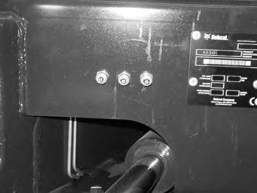
Figure 250
The pivots and cylinders (Item 1) have a large pin held in position with a bolt (Item 2) and double nuts (Item 3) [Figure 250] securing the pin.
The the two nuts (Item 3) are used as jam nuts to hold the bolt (Item 2) with out tightening the bolt (Item 2) to the pin boss. After the nuts (Item 3) are tightened together, the bolt (Item 2) should be free to spin. See your Bobcat dealer for replacement parts.
EXCAVATOR STORAGE AND RETURN TO SERVICE Storage
Sometimes it may be necessary to store your Bobcat excavator for an extend period of time. Below is a list of items to perform before storage.
•Thoroughly clean the excavator including the engine compartment.
•Lubricate the excavator.
•Replace worn or damaged parts.
•Drive the excavator onto planks in a dry protected shelter.
•Lower the boom fully with the bucket flat on the ground.
•Put grease on any exposed cylinder rods.
•Put fuel stabiliser in the fuel tank and run the engine a few minutes to circulate the stabiliser to the pump and fuel injectors.
•Drain and flush the cooling system. Refill with premixed coolant.
•Replace all fluids and filters (engine, hydraulic).
•Replace all filters (i.e.: air cleaner, heater, etc.).
•Put all controls in NEUTRAL position.
•Remove the battery. Be sure the electrolyte level is correct then charge the battery. Store it in a cool dry place above freezing temperatures and charge it periodically during storage.
•Cover the exhaust pipe opening.
•Tag the machine to indicate that it is in storage condition.
Return To Service
After the Bobcat excavator has been in storage, it is necessary to follow a list of items to return the excavator to service.
•Check the engine and hydraulic oil levels; check coolant level.
•Install a fully charged battery.
•Remove grease from exposed cylinder rods.
•Check all belt tensions.
•Be sure all shields and guards are in place.
•Lubricate the excavator.
•Remove cover from exhaust pipe opening.
•Start the engine and let run for a few minutes while observing the instrument panels and systems for correct operation.
•Drive the excavator off of the planks.
•Operate machine, check for correct function.
•Stop the engine and check for leaks. Repair as needed.

Diagnostic Service Codes
Number Codes List
CODE CODE
C0216Hydraulic charge filter not connected
C0217Hydraulic charge filter plugged
C0309Battery voltage low
C0310Battery voltage high
C0311Battery voltage extremely high
C0314Battery voltage extremely low
C0315Battery voltage shutdown level
C0322Battery voltage out of range low
C0414Oil pressure extremely low
C0415Oil pressure shutdown level
C0610Engine speed high
C0611Engine speed extremely high
C0613Engine speed no signal
C0615Engine speed shutdown level
C0618Engine speed out of range high
C0710Hydraulic oil temperature high
C0711Hydraulic oil temperature extremely high
C0715Hydraulic oil temperature shutdown level
C2005Two speed solenoid error ON
C2006Two speed solenoid error OFF
C2102Glow plugs error ON
C2103Glow plugs error OFF
C2202Starter error ON
C2203Starter error OFF
C2305Offset base solenoid short to battery
C2306Offset base solenoid short to ground
C2307Offset base solenoid open circuit
C2405Offset rod solenoid short to battery
C2406Offset rod solenoid short to ground
C2407Offset rod solenoid open circuit
C2505Offset return short to battery
C2506Offset return short to ground
C2507Offset return open circuit
C2605Auxiliary base solenoid short to battery
C0721Hydraulic oil temperature out of range highC2606Auxiliary base solenoid short to ground
C0722Hydraulic oil temperature out of range low
C0810Engine coolant temperature high
C2607Auxiliary base solenoid open circuit
C2705Auxiliary rod solenoid short to battery
C0811Engine coolant temperature extremely highC2706Auxiliary rod solenoid short to ground
C0815Engine coolant temperature shutdown levelC2707Auxiliary rod solenoid open circuit
C0821Engine coolant temperature out of range high
C0822Engine coolant temperature out of range lowC2805Hydraulic exchange error ON C2806Hydraulic exchange error OFF
C0921Fuel level out of range high
C0922Fuel level out of range low
C1221Front auxiliary control out of range high
C1222Front auxiliary control out of range low
C1223Front auxiliary control not in NEUTRAL
C3028Controller memory failure (Log only)
C3128Interrupted power failure (Log only)
C3323Main controller not programmed
C1305Fuel shut-off hold solenoid short to batteryC3397Main controller programmed (Log only)
C1306Fuel shut-off hold solenoid short to earth
C1307Fuel shut-off hold solenoid open circuit
C1402Fuel shut-off hold solenoid short error on
C1403Fuel shut-off hold solenoid short error off
DIAGNOSTICS SERVICE CODE (CONT’D)
Number Codes List (Cont’d)
Code
C4021Angle blade control out of range high
C4022Angle blade control out of range low
C4023Angle blade control not in NEUTRAL
Code
E0105Throttle actuator short to battery
E0106Throttle actuator short to earth
E0107Throttle actuator open circuit
C4105Angle blade base solenoid short to batteryE01233Throttle actuator not calibrated
C4106Angle blade base solenoid short to earth
C4107Angle blade base solenoid open circuit
C4205Angle blade rod solenoid short to battery
C4206Angle blade rod solenoid short to earth
C4207Angle blade rod solenoid open circuit
C4321Load sense pressure out of range high
C4322Load sense pressure out of range low
C4416Auxiliary controller not connected (Tilt rotator option only)
C4516Throttle controller not connected
C6021Offset controller out of range high
C6022Offset controller out of range low
C6023Offset controller not in NEUTRAL
C6204Load moment in error
C6305Console sensor short to battery
C6306Console sensor short to earth
C6405Switched power relay short to battery
C6406Switched power relay short to earth
C6407Switched power relay open circuit
C6505Work group lockout short to battery
C6506Work group lockout short to earth
C6507Work group lockout open circuit
E03215 volt supply out of range high
E03225 volt supply out of range low
E0421Throttle sensor out of range high
E0422Throttle sensor out of range low
E0521Throttle actuator feedback out of range high
E0522Throttle actuator feedback out of range low
E3128 Interrupted power failure log only
E3297 Controller programmed log only
Passwords
All new machines with keyless option arrive at the Bobcat Dealerships with the panel in locked mode. This means that a password must be used to start the engine.
For security purposes, your dealer may change the password and also set it in the locked mode. Your dealer will provide you with the password.
Master Password: A permanent, randomly selected password is set at the factory which cannot be changed. This password is used for service by the Bobcat dealer if the Owner Password is not known; or to change the Owner Password.
Owner Password: There is only one Owner Password (CodE 0). It must be used to change the owner or operator passwords. See below for changing the Owner Password.
Operator Password: There can be up to three operator Passwords (CodE 1, CodE 2, CodE 3). See below for changing the Operator Password.
Password Entry (For Starting And Operating The Machine)
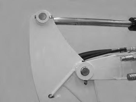
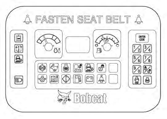
Press [ENTER CODE] button (Item 1). The panel will become lighted and there will be two short beeps. [CodE] will appear on the data display screen (Item 2) [Figure 251]
NOTE: After you press [ENTER CODE] you have 40 seconds to use the keypad (Item 3) [Figure 251] to enter the password. (If more than 40 seconds is used, the process will abort and you will need to start over.
Enter the password. For each digit that you enter, a dash will appear on the data display screen. If the password was entered correctly, there will be one long beep.
NOTE: If the password was incorrect there will be three short beeps and [Error] will appear on the data display screen. Press the [ENTER CODE] button again and start over. After three failed attempts, you must wait three minutes to try again.
You are now ready to start and operate the machine.
If you will be changing the operator password, do not start the engine. (See Changing The Operator Password on Page 157.)
Figure 251
Changing The Operator Password
Perform Password Entry at left, but do not start the engine.
Press and hold the [ENTER CODE] button (Item 1) for three seconds. [CodE 1] will appear on the data display screen (Item 2) [Figure 251]
Press the [ENTER CODE] button until the desired Code (CodE 0, CodE 1, CodE 2, CodE 3) appears. CodE 0 is Owner Password, the other codes are Operator passwords.You now have 40 seconds to use the keypad (Item 3) [Figure 251] to enter each digit of a new four digit password.
Enter the new four digit password. After the fourth digit is entered, there will be two short beeps and [rPEAt] will appear.
Re-enter the new four digit password to verify. If the new passwords match, there will be two short beeps, [Code] will appear for 1 second and then the data display screen will return to HOURMETER function.
NOTE: If the new passwords do not match, there will be one long beep and [Error] will appear for 1 second and then the data display screen will return to HOURMETER function.
DISPLAY CONTROLLER PANEL SETUP (CONT’D)
Password Lockout Feature
This allows the operator to Unlock the password feature so that a password does not need to be used every time you start the engine.
Perform Password Entry ((See Password Entry (For Starting And Operating The Machine) on Page 157.)) (the engine can be started or stopped.) The password entry can be performed with the engine off or with the engine running.
Figure 252
Press the Lock / Unlock button (Item 1). The data display screen (Item 5) [Figure 252] will continuously alternate from UnLoc to CodE for 1 second periods.
Perform Password Entry again.
[UnLoc] will appear in the data display screen (Item 5), the Unlocked Icon (Item 2) will appear in the Icon Display Area (Item 3) [Figure 252] and there will be two short beeps.
To start an Unlocked system, press the [ENTER CODE] button and press the START button.
When you stop the engine with the system unlocked, you will hear one long beep every 3 seconds for 15 seconds.
To lock the system again, press the Lock / Unlock button (Item 1) [Figure 252] and enter the password during the 15 second period.
Job Clock
The JOB CLOCK can be set to record accumulated hours for a particular job.
Press and release the information button (Item 4) until JOB light is ON at the top, centre of the data display screen (Item 5) [Figure 252]
While the JOB light is ON, press and hold the information button (Item 4) [Figure 252] until the data display screen returns to zero.
This process will clear the accumulated hours and will begin recording JOB CLOCK time again. (This does not affect the HOURMETER which continues to record the total operating hours of the excavator.)
Pressing the information button (Item 4) [Figure 252] again or pressing the START button will return the data display screen to HOURMETER function.
Rpm
The data display screen (Item 5) [Figure 252] can be set to display engine rpm.
With the engine running, press and release the information button (Item 4) until RPM light is ON at the top, centre of the data display screen (Item 5) [Figure 252]
Engine RPM is now displayed in the data display screen.
Press the information button (Item 4) [Figure 252] again the return to HOURMETER function.