7 minute read
PUBLICATIONS AND TRAINING RESOURCES


The following publications are also available for your Bobcat loader. You can order them from your Bobcat dealer.
For the latest information on Bobcat products and the Bobcat Company, visit our Web site at www.bobcat.eu.
OPERATION & MAINTENANCE MANUAL
6989436enGB
Complete instructions on the correct operation and the routine maintenance of your Bobcat loader.
SERVICE MANUAL
6989437enUS
Complete maintenance instructions for your Bobcat loader.
OPERATOR’S HANDBOOK
6987271enGB
Gives basic operation instructions and safety warnings.
MACHINE SIGNS (DECALS)
Follow the instructions on all the Machine Signs (Decals) that are on the excavator. Replace any damaged machine signs and be sure they are in the correct locations. Machine signs are available from your Bobcat excavator dealer.
MACHINE SIGNS (DECALS) (CONT’D)
Follow the instructions on all the Machine Signs (Decals) that are on the excavator. Replace any damaged machine signs and be sure they are in the correct locations. Machine signs are available from your Bobcat excavator dealer.
MACHINE SIGNS (DECALS) (CONT’D)
Pictorial Only Safety Signs
Safety signs are used to alert the equipment operator or maintenance person to hazards that may be encountered in the use and maintenance of the equipment. The location and description of the safety signs are detailed in this section. Please become familiarized with all safety signs installed on the excavator.
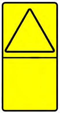
Vertical Configuration
NOTE:See the numbered MACHINE SIGNS (DECALS) on Page 22 and Machine Signs (Decals) (Cont’d) on Page 23 for the machine location of each corresponding numbered pictorial only decals as shown below.
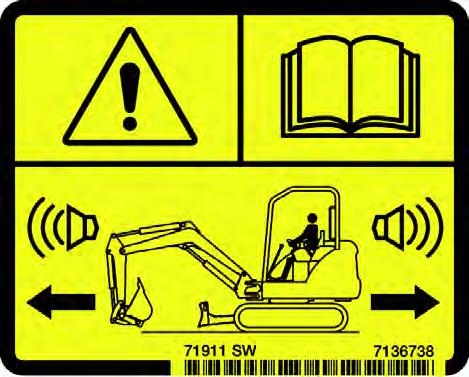
1.Motion Alarm (7136738)
This safety sign is located on the right rear console.
HAZARD PANEL
AVOIDANCE PANEL
Horizontal Configuration
Warning
This machine is equipped with a motion alarm. ALARM MUST SOUND! when operating forward or backward.
Failure to maintain a clear view in the direction of travel could result in serious injury or death.
HAZARD PANEL AVOIDANCE PANEL
The format consists of the hazard panel(s) and the avoidance panel(s):
Hazard panels depict a potential hazard enclosed in a safety alert triangle.
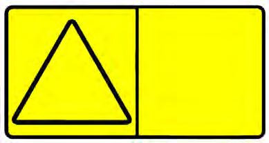
Avoidance panels depict actions required to avoid the hazards.
A safety sign may contain more than one hazard panel and more than one avoidance panel.
The operator is responsible for the safe operation of this machine.
W-2786-0309
MACHINE SIGNS (DECALS) (CONT’D)
Pictorial Only Safety Signs (Cont’d)
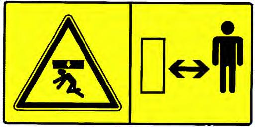
2.Crush Hazard (6713507)
This safety sign is located on both sides of the boom.
Warning
Keep away from the operating machine to avoid serious injury or death.
W-2520-0106
3.Thrown Or Flying Objects (7168039)
This safety sign is located on the outside of both tracks.
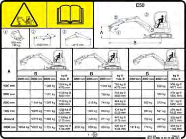
4.Transporting And Lifting (7178215)
This safety sign is located on the front of the cab.
Warning
High pressure grease can cause serious injury. Do not loosen grease fitting. Do not loosen bleed fitting more than 1 - 1/2 turns.
Read and understand the Operation & Maintenance Manual for more information.
W-2516-0110
Warning
Improper loading, transporting and lifting procedures can cause serious injury or death. Read and understand the Operation & Maintenance Manual prior to transporting or lifting the machine.
W-2517-0110
MACHINE SIGNS (DECALS) (CONT’D)
Pictorial Only Safety Signs (Cont’d)
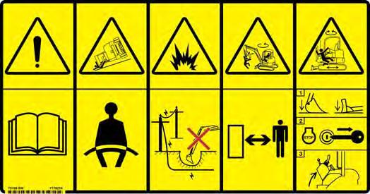
5.General Hazard (7148158, 7178216)
This safety sign is located inside the operator’s area on the right rear window.
Warning
Failure to obey warning signs and instructions can cause serious injury or death. Never use excavator without instructions. Read and understand the Operation & Maintenance Manual and Handbook.
Keep away from dropoffs, steep areas or banks that could break away.
Explosion or electrocution can occur if machine contacts utility lines or pipes. Check for overhead or underground lines before operating.
Keep bystanders away. No riders. Check location of blade for direction of travel before moving steering controls.
Failure to operate machine from the operator’s position can cause serious injury or death.
To Leave Excavator:
1. Lower attachment and blade to ground.
2. Stop engine and remove the key (if equipped).
3. Raise control console.
W-2518-0110
6.Lift Capacity (7188431, 7188433)
This safety sign is located on the right side cover.
Warning
Overload can tip the excavator and cause serious injury or death.
•Do not lift or hold any load that exceeds these ratings at their specific load radii and height.
•Total rated load is shown. The weight of all lifting devices must be deducted to determine the net load that can be lifted.
Read and understand the Operation & Maintenance Manual for more information.
W-2519-0110
7.Hot Surfaces and Rotating Fan (7185934)
This safety sign is located inside the engine compartment.
Warning
Rotating fan blade can cause serious injury or death. Keep away from fan and moving parts. Do not operate with guard removed.
Hot surfaces can cause injury. Do not touch. Allow to cool before servicing.
W-2521-0106
MACHINE SIGNS (DECALS) (CONT’D)
Pictorial Only Safety Signs (Cont’d)
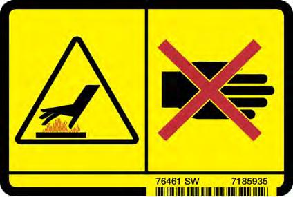
8.Hot Surfaces (7185935)
This safety sign is located in the engine compartment.
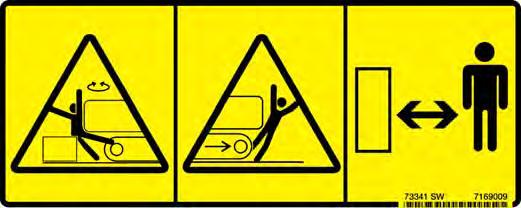
9.Stay Away (7169009)
This safety sign is located on both upper rear corners of the upperstructure.
Warning
AVOID BURNS
Do not remove radiator cap when the engine is hot. You can be seriously burned.
W-2070-1203
Warning
AVOID INJURY OR DEATH
•Keep out of swing area or travel path.
•Always look in the direction of travel.
•Make sure swing area is clear of bystanders and objects.
W-NEW-1108
MACHINE SIGNS (DECALS) (CONT’D)
Pictorial Only Safety Signs (Cont’d)
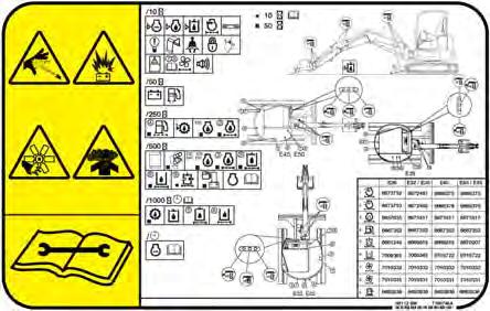
10.High Pressure, Battery, Rotating Fan, Exhaust Gases and Service Schedule (7188748)
This safety sign is located in the engine compartment. For Service Schedule Information, (See SERVICE SCHEDULE on Page 109.)
11. Thrown or Flying Objects (7169291)
This safety sign is located on the gas spring in the engine compartment.
Warning
7169291
High pressure gas can cause serious injury or death. Do not open. Opening cylinder can release rod.
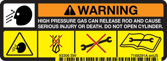
W-2523-0106
Warning
Leaking fluids under pressure can enter the skin and cause serious injury or death. Immediate medical attention is required. Wear goggles. Use cardboard to check for leaks.
Battery makes flammable and explosive gas. Keep arcs, sparks, flames and lighted tobacco away. Keep away from electrical contacts
Rotating fan can cause serious injury. Keep away from fan and moving parts. Do not operate with guard removed.
All exhaust gases can kill. Always ventilate.
Read and understand the Operation & Maintenance Manual for more information.
W-2522-0110

Instruments And Consoles
Cab Interior Light (If Equipped)
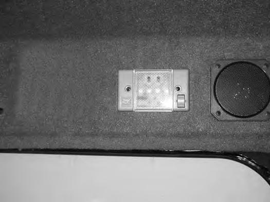
Press the top of the switch (Item 1) [Figure 7] to turn the light ON. Press the bottom of the switch to turn OFF
Left Console
1 Left Joystick (See HYDRAULIC CONTROLS on Page 49.)
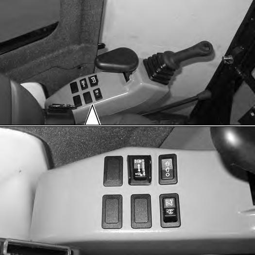
2 Horn Press the switch on the bottom of the left joystick to sound horn.
3 Boom Swing Switch / Secondary Auxiliary Hydraulic (If Equipped)
4 Wiper / Washer Switch (If Equipped)
Move the switch to the left to swing the boom to the left. Move the switch to the right to swing the boom to the right. (See Secondary Auxiliary Hydraulics and Boom Swing in this manual.)
Press the switch to the left to turn wiper ON. Press and hold switch to the left to activate window washer. Press the switch to the right to turn wiper OFF.
5 Hydraulic XChange Switch (If Equipped)
6 Beacon / Strobe Light (If Equipped)
Press and hold the switch to the right to fully retract hydraulic pins. Press and hold the switch to the left to fully extend hydraulic pins.
Press switch to the left to turn ON the beacon / Strobe light. Press the switch to the right to turn OFF.
7 Not Used- - -
8 Not Used- - -
9 Boom Swing Switch / Secondary Auxiliary Hydraulic
Move the switch to the right to activate the secondary auxiliary hydraulics. Move the switch to the left for boom swing function. (See Secondary Auxiliary Hydraulics and Boom Swing in this manual.)
INSTRUMENTS AND CONSOLES (CONT’D)
Right Console
Figure 9
REF. DESCRIPTION
FUNCTION / OPERATION
1 Right Joystick(See HYDRAULIC CONTROLS in this manual.)
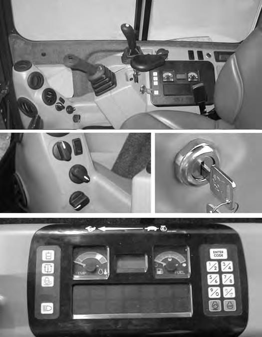
2 Auxiliary Hydraulic Switch Controls the fluid flow to the auxiliary quick couplers (attachment). (See Auxiliary Hydraulics in this manual.)
3 Blade Control LeverControls raising and lowering the blade. Pushed all the way forward puts blade in float position. (See BLADE LEVER CONTROL in this manual).
4 Engine Speed Control Dial Controls rpm of the engine. (See ENGINE SPEED CONTROL DIAL in this manual).
5 Two Speed ButtonEngages and disengages High Range Travel Speed. (See TwoSpeed Travel in this manual).
6 Motion Alarm Cancel Switch This switch temporarily disables the motion alarm. (See MOTION ALARM SYSTEM on Page 46.)
7 Not Used---
8 Auxiliary Power Outlet
9 Key Switch (STANDARD Panel Only)
12 volt receptacle for accessories.
Always perform the PRESTARTING PROCEDURE. (See PRE-STARTING PROCEDURE in this manual), before starting the engine. (See STARTING THE ENGINE in this manual).
REF. DESCRIPTION FUNCTION / OPERATION
10 Air Conditioning Switch (If Equipped) Press top of switch to turn air conditioner ON (light in switch will be ON), Press bottom of switch to turn OFF.
11 Fan Motor Switch (If Equipped) Turn clockwise to increase fan speed; anticlockwise to decrease.
12 Temperature Control (If Equipped)
Turn clockwise to increase temperature; anticlockwise to decrease.
13 Recirculation / Fresh Air Control Turn clockwise for fresh air; anticlockwise for recirculation. (Use recirculation mode for increased heating and cooling efficiency.)
14 Auxiliary Hydraulic Button Activates and deactivates auxiliary hydraulic function (Selectable Auxiliary Hydraulic Flow) (Audible beep sounds each time the button is pressed.) (See Auxiliary Hydraulics in this manual)
15 Information Cycles through (after each button press): Hours, Job Clock, Engine rpm, Selectable Auxiliary Hydraulic Flow (when activated); in the data Display, Item 19.)
16 Auto Idle FeaturePress once to turn Auto Idle Feature ON, press a second time to turn OFF. (See Auto Idle Feature in this manual).
17 LightsPress once to turn lights ON; press again to turn lights OFF.
18 TemperatureShows the engine coolant temperature.
19 Data Display Screen The data display screen shows the Hourmeter during normal operation of the excavator. When preheat is activated, the display screen will show the remaining preheat time. Can also be used to display Job Clock, Engine rpm, and Selectable Auxiliary Hydraulic Flow. (See Job Clock in this manual).
20 Fuel GaugeShows the amount of fuel in the tank.
21 Keyless (OPTIONAL) (Always perform the PRESTARTING PROCEDURE, (See PRE-STARTING PROCEDURE in this manual), before starting the engine. (See STARTING THE ENGINE in this manual).
22 Indicator Icons(See Indicator Icons in this manual).
NOTE: Always turn key switch and all accessories to OFF position when the engine is stopped, the battery will discharge if the key is left ON. Audible alarm will sound if the key is in the ON position with the engine stopped.