35 minute read
MAINTENANCE SAFETY


Instructions are necessary before operating or servicing machine. Read and understand the Operation & Maintenance Manual, Operator’s Handbook and signs (decals) on machine. Follow warnings and instructions in the manuals when making repairs, adjustments or servicing. Check for correct function after adjustments, repairs or service. Untrained operators and failure to follow instructions can cause injury or death.
W-2003-0807
Safety Alert Symbol: This symbol with a warning statement, means: “Warning, be alert! Your safety is involved!” Carefully read the message that follows.
Never service the Bobcat Compact Excavator without instructions.
Use the correct procedure to lift and support the excavator.
Cleaning and maintenance are required daily.
Have good ventilation when welding or grinding painted parts. Wear dust mask when grinding painted parts. Toxic dust and gas can be produced.
Vent exhaust to outside when engine must be run for service. Exhaust system must be tightly sealed. Exhaust fumes can kill without warning.
Always lower the bucket and blade to the ground before doing any maintenance. Never modify equipment or add attachments not approved by Bobcat Company.
Stop, cool and clean engine of flammable materials before checking fluids. Never service or adjust machine with the engine running unless instructed to do so in the manual.
Avoid contact with leaking hydraulic fluid or diesel fuel under pressure. It can penetrate the skin or eyes.
Never fill fuel tank with engine running, while smoking, or when near open flame.
Keep body, jewelry and clothing away from moving parts, electrical contact, hot parts and exhaust. Wear eye protection to guard from battery acid, compressed springs, fluids under pressure and flying debris when engines are running or tools are used. Use eye protections approved for type of welding. Keep tailgate closed except for service. Close and latch tailgate before operating the excavator.
Lead-acid batteries produce flammable and explosive gases. Keep arcs, sparks, flames and lighted tobacco away from batteries.
Batteries contain acid which burns eyes or skin on contact. Wear protective clothing. If acid contacts body, flush well with water. For eye contact flush well and get immediate medical attention.
Maintenance procedures which are given in the Operation & Maintenance Manual can be performed by the owner/ operator without any specific technical training. Maintenance procedures which are not in the Operation & Maintenance Manual must be performed ONLY BY QUALIFIED BOBCAT SERVICE PERSONNEL. Always use genuine Bobcat replacement parts. The Service Safety Training Course is available from your Bobcat dealer.
MSW38-0409

Service Schedule
Maintenance Intervals
Maintenance work must be done at regular intervals. Failure to do so will result in excessive wear and early failures.
The service schedule is a guide for correct maintenance of the Bobcat excavator.
Warning
Avoid Injury Or Death
Instructions are necessary before operating or servicing machine. Read and understand the Operation & Maintenance Manual, Operator’s Handbook and signs (decals) on machine. Follow warnings and instructions in the manuals when making repairs, adjustments or servicing. Check for correct function after adjustments, repairs or service. Untrained operators and failure to follow instructions can cause injury or death.
W-2003-0807
Every 10 Hours (Before Starting The Excavator)
• Engine Oil - Check level and add as needed.
• Engine Air Filters and Air System - Check display panel. Service only when required. Check for leaks and damaged components.
• Engine Cooling System - Check coolant level COLD and add premixed coolant as needed.
• Hydraulic Fluid - Check fluid level and add as needed.
• Fuel Filter - Drain water and sediment from filter.
• Seat Belt, Seat Belt Retractors, Seat Belt Mounting hardware, Control Console Lockout - Check the condition of seat belt and mounting hardware. Clean or replace seat belt retractors as needed. Check the control console lockout lever for proper operation. Clean dirt and debris from moving parts.
• Motion Alarm - Check for proper function.
• Operator Canopy / Cab - Check the canopy / cab condition and mounting hardware.
• Operator Cab and HVAC Filters - Clean filters as needed.
• Indicators and Lights - Check for correct operation of all indicators and lights.
• Safety Signs - Check for damaged signs (decals). Replace any signs that are damaged.
• Track Tension - Check tension and adjust as needed.
• Pivot Points - Grease all machinery pivot points. Grease clamp and angle blade (if equipped).
• X-Change / Attachment Coupler - Check for damage or loose parts (if equipped).
Every 50 Hours
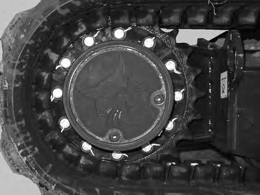
• Swing Bearing - Grease swing bearing and swing pinion. Service every 10 hours when operating in water.
• Battery - Check cables, connections, and electrolyte level; add distilled water as needed.
• Fuel Tank - Drain water and sediment from fuel tank and fuel filter.
Every 250 Hours Or Every 12 Months
• Travel Motors (Final Drive) - Service at first 50 hours, then as scheduled. Check fluid level and add as needed.
SS EXC E32 - E55 iT4 T4-K-0815
SERVICE SCHEDULE (CONT’D)
Maintenance Intervals (Cont’d)
Every 500 Hours Or Every 12 Months
• Engine Oil and Filter - Service at first 50 hours, then as scheduled. Replace oil and filter.
• Fuel Filter – Replace filter element.
• Cooling System - Clean debris from radiator, fuel cooler, hydraulic fluid cooler, air conditioning condenser (if equipped).
• Hydraulic Filter, Case Drain Filter and Hydraulic Reservoir Breather Cap - Service at first 50 hours, then as scheduled. Replace the hydraulic filter, case drain filter and the reservoir breather cap.
• Drive Belts (Alternator) (Air Conditioning - If Equipped) - Check condition. Replace as needed. Service at first 50 hours, then as scheduled.
• Alternator and Starter - Service at first 50 hours, then as scheduled. Check connections.
• HVAC - Clean housing and coils.
Every 1000 Hours Or Every 12 Months
• Swing Cylinder Base End - Grease swing cylinder base end grease fitting.
• Hydraulic Fluid and Filters - Replace hydraulic fluid and filters.
• Travel Motors (Final Drive) - Service at first 50 hours, then as scheduled. Replace fluid.
• Engine Valves - Adjust the engine valve clearance.
Every 24 Months
• Coolant - Replace the coolant.
SERVICE SCHEDULE (CONT’D)
Inspection Checkbook
Regularly scheduled maintenance is essential to continuous operation and operating safety. The life expectancy of your machine depends on proper and meticulous care.
The Inspection Checkbook contains the following information:
Doosan Benelux S.A. Warranty Conditions
Protection Plus Extended Warranty Conditions
General Parts Policy
General Information
First Inspection
Scheduled Services
Identification
Authorised Identification
Lubricants and Fluids Table Service Parts Chart
Your local dealer can order the Inspection Checkbook. Part number: 4420310.
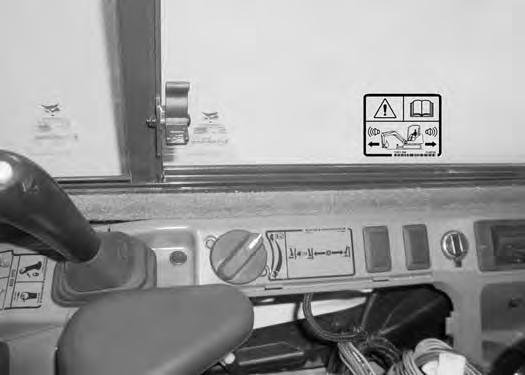
Control Console Lockouts
Inspection And Maintenance
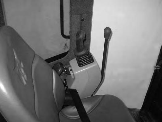
Figure 164
When the left console is raised [Figure 164], the hydraulic control levers (joysticks) and traction system must not function.
Sit in the operator's seat, fasten the seat belt and start the engine.
Raise the left console [Figure 164]
Move the joystick control levers. There should be no movement of the boom, arm, slew or bucket.
Move the steering control levers. There should be no movement of the excavator tracks.
Service the system if these controls do not deactivate when the left control console is raised. (See your Bobcat dealer for service.)
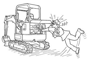
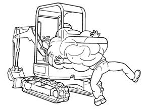
Failure to properly inspect and maintain the seat belt can cause lack of operator restraint resulting in serious injury or death.
W-2466-0703
Check the seat belt daily for correct function.
Inspect the seat belt system thoroughly at least once each year or more often if the machine is exposed to severe environmental conditions or applications.
Any seat belt system that shows cuts, fraying, extreme or unusual wear, significant discolourations due to ultraviolet UV exposure, dusty / dirty conditions, abrasion to the seat belt webbing, or damage to the buckle, latch plate, retractor (if equipped), hardware or any other obvious problem should be replaced immediately.
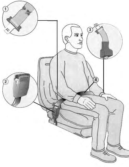
The items below are referenced in [Figure 165]
1.Check the webbing. If the system is equipped with a retractor, pull the webbing completely out and inspect the full length of the webbing. Look for cuts, wear, fraying, dirt and stiffness.
2.Check the buckle and latch for correct operation. Make sure latch plate is not excessively worn, deformed or buckle is not damaged or casing broken.
3.Check the retractor web storage device (if equipped) by extending webbing to determine if it looks correct and that it spools out and retracts webbing correctly.
4.Check webbing in areas exposed to ultraviolet (UV) rays from the sun or extreme dust or dirt. If the original colour of the webbing in these areas is extremely faded and / or the webbing is packed with dirt, the webbing strength may have deteriorated.
See your Bobcat dealer for seat belt system replacement parts for your machine.
MOTION ALARM SYSTEM Description
This excavator may be equipped with a motion alarm system. The motion alarm will sound when the operator moves the travel control levers in either the forward or reverse direction. Slight movement of the steering levers in either the forward or reverse direction is required with hydraulic components before the motion alarm will sound.
Warning
Avoid Injury Or Death
When an engine is running in an enclosed area, fresh air must be added to avoid concentration of exhaust fumes. If the engine is stationary, vent the exhaust outside. Exhaust fumes contain odorless, invisible gases which can kill without warning.
Sit in the operator’s seat and fasten the seat belt. Start the engine. (See PRE-STARTING PROCEDURE on Page 62.)
Move the travel control levers (one lever at a time) in the forward direction. The motion alarm must sound. Move the travel control levers (one lever at a time) in the reverse direction. The motion alarm must sound.
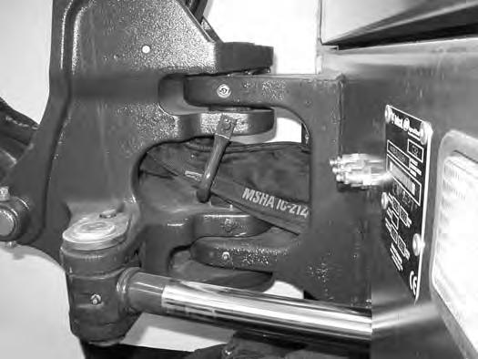
Inspect for damaged or missing motion alarm decal (Item 1) [Figure 166] (cab machine) or (Item 1) [Figure 167] (canopy machine). Replace if required.
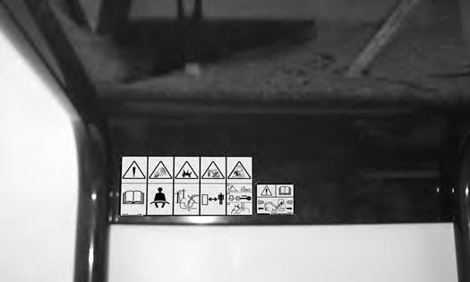
NOTE:The excavator will need to be moved slightly in both the forward and reverse direction to test the motion alarm. Keep all bystanders away from machine during test.
Slightly move both travel control levers in the forward direction (until the machine is slowly moving forward) and then press the motion alarm cancel switch (Item 1) [Figure 168]. The motion alarm will shut off. With the machine still moving forward, move one of the levers to the NEUTRAL position, the motion alarm must sound.
Slightly move both travel control levers in the reverse direction (until the machine is slowly moving backward) and then press the motion alarm cancel switch (Item 1) [Figure 168] (the switch icon will be illuminated when the motion alarm is deactivated). The motion alar m will shut off. With the machine still moving backward, move one of the levers to the NEUTRAL position, the motion alarm must sound.
Return both levers to NEUTRAL and turn excavator key to OFF position. Exit the excavator. (See STOPPING THE ENGINE AND LEAVING THE EXCAVATOR on Page 69.)
MOTION ALARM SYSTEM (CONT’D)
Inspecting (Cont’d)
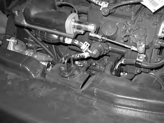
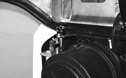
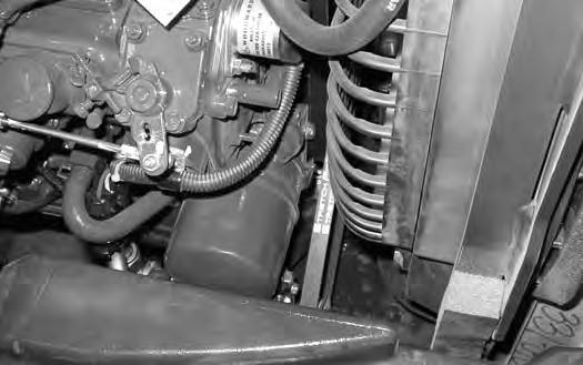
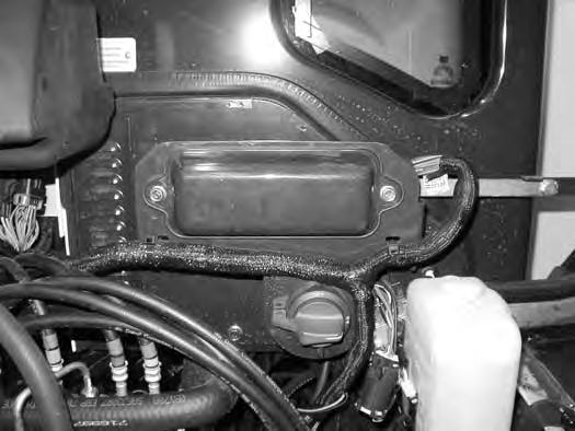
The motion alarm is mounted to the bottom rear of the excavator. (To the front of the engine oil pan.)
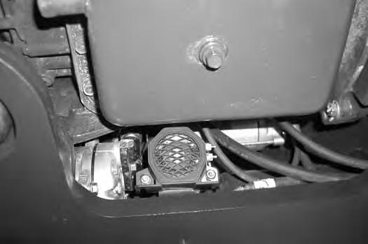
Figure 169
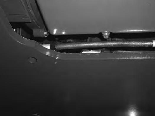
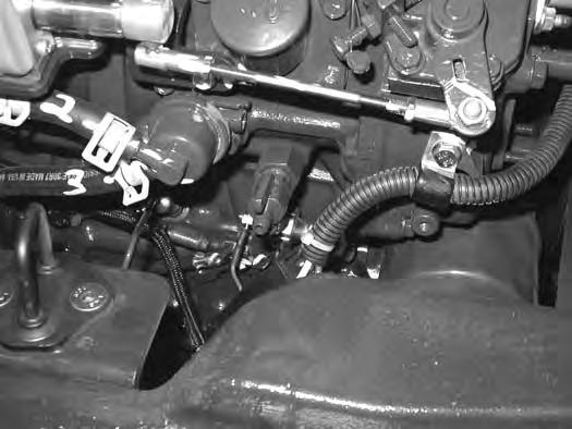
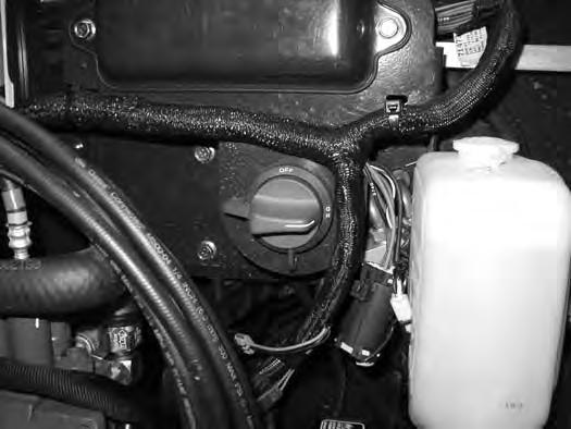
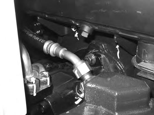
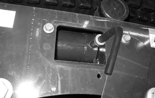
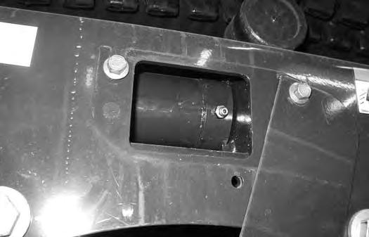
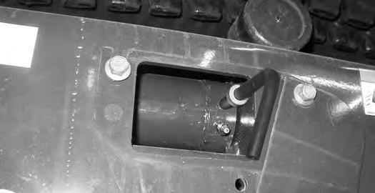
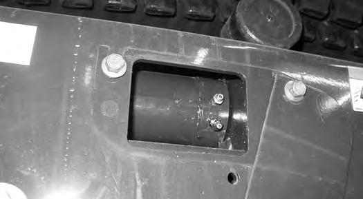
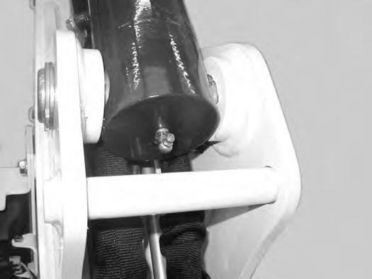
Inspect the motion alarm electrical connections and wire har ness (Item 1) [Figure 169], wire harness (Item 1) [Figure 170] and motion alarm switch (Item 2) [Figure 170] for tightness and damage. Repair or replace any damaged components.
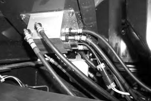
If the motion alarm switch requires a service, see the following information.
Adjusting Switch Position
Figure 170
The switch (Item 2) [Figure 170] is non-adjustable. It must be fully installed into the travel control valve housing and tightened. Tighten the switch to 18 - 20 N•m (13 - 15 ft-lb).
Inspect the motion alarm system for proper function after switch replacement.
Warning
This machine is equipped with a motion alarm. ALARM MUST SOUND! when operating forward or backward.
Failure to maintain a clear view in the direction of travel could result in serious injury or death.
The operator is responsible for the safe operation of this machine.
Opening And Closing
Warning
Avoid Injury Or Death
Never service or adjust the machine when the engine is running unless instructed to do so in the manual.

Warning
Keep the rear door closed when operating the machine. Failure to do so could seriously injure a bystander.
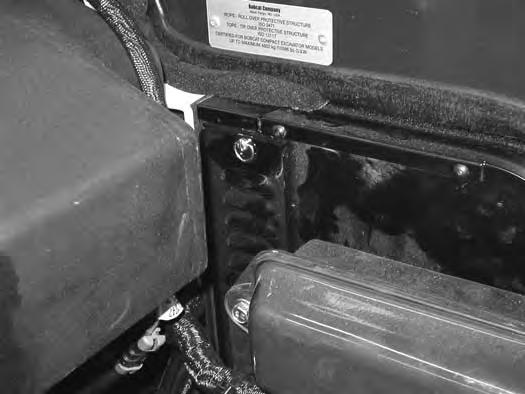
Adjusting The Latch
Pull the latch (Item 1) [Figure 171] and open the tailgate. Push firmly to close the tailgate.
NOTE: The tailgate can be locked using the start key.
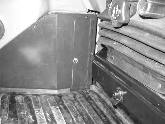
Open the tailgate to access the right side cover latch (Item 1) [Figure 173]
Pull the latch handle (Item 1) [Figure 173] out until the right side cover is unlatched.
Raise the right side cover and rotate forward until it is held open by the retainer (Item 1) [Figure 174]
To close the right side cover, lift up on the retainer (Item 1) [Figure 174] while raising the right side cover. Rotate the cover back until it is in the fully closed position. Secure the right side cover with the latch (Item 1) [Figure 173]
Cab Filters
Cleaning And Maintenance
The recirculation filter and the fresh air filter must be cleaned regularly. (See SERVICE SCHEDULE on Page 109.)
The recirculation filter is located to the right of the operator seat and the fresh air filter is located under the right side cover. Recirculation Filter
Fresh Air Filter
Figure 177
Turn the fastener (Item 1) 1/4 turn and open the cover (Item 2) [Figure 175]
Open the right side cover. (See RIGHT SIDE COVER on Page 116.)
Turn the fastener (Item 1) 1/4 turn and remove the cover (Item 2) [Figure 177]
178
Pull the filter (Item 1) [Figure 176] out of the heater housing.
Use low air pressure to clean the filter. Replace the filter when very dirty.
Installation: Install the filter with the arrows that indicate air flow direction (Item 2) [Figure 176] pointing toward the heater housing.
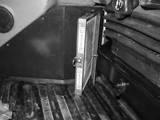
Pull the filter (Item 1) [Figure 178] out of the housing.
Use low air pressure to clean the filter. Replace the filter when very dirty.
Air Cleaner Service
See the SERVICE SCHEDULE for the correct service interval. (See SERVICE SCHEDULE on Page 109.)
Daily Check
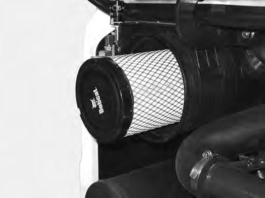
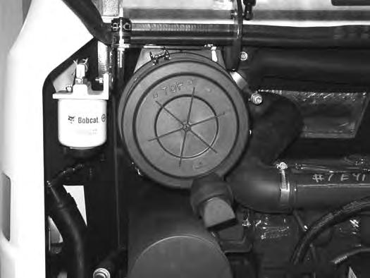
The air cleaner is located in the engine compartment. Open the tailgate to access the air cleaner for service. (See TAILGATE on Page 115.)
Figure 179
Check the condition indicator (Item 1) [Figure 179]. If the red ring shows in the condition indicator, the filter needs to be replaced.
Replace the inner filter every third time the outer filter is replaced or as indicated.
Replacing Filter Elements
Outer Filter
Figure 180
Release the three fasteners (Item 1) [Figure 180]
Remove and clean the dust cup (Item 2) [Figure 180]
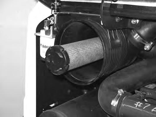
Figure 181
Pull the outer filter (Item 1) [Figure 181] from the air cleaner housing.
Check the housing for damage.
Clean the housing and the seal surface. DO NOT use compressed air.
Install a new filter.
182
Install the dust cup (Item 1) and engage the three fasteners (Item 2) [Figure 182]
Check the air intake hose and the air cleaner housing for damage. Make sure all connections are tight.
After the outer filter has been replaced, press the button (Item 1) [Figure 179] on the end of the condition indicator and start the engine. Run at full rpm, then reduce engine speed and stop the engine. If the red ring (Item 2) [Figure 179] shows in the condition indicator, replace the inner filter.
AIR CLEANER SERVICE (CONT’D)
Replacing Filter Elements (Cont’d)
Inner Filter
Only replace the inner filter under the following conditions:
•Replace the inner filter every third time the outer filter is replaced.
•After the outer filter has been replaced, press the button (Item 2) [Figure 179] on the end of the condition indicator. Start the engine. Run the engine at full rpm, then reduce engine speed. Stop the engine. If the red ring shows in the condition indicator, replace the inner filter.
Remove the dust cup, outer filter and inner filter (Item 1) [Figure 183]
NOTE: Make sure all sealing surfaces are free of dirt and debris.
Install the new inner filter.
Install the outer filter and the dust cup.
Press the button on the condition indicator to remove the red ring.
Close the tailgate.
Fuel System
Fuel Specifications
NOTE: Contact your local fuel supplier to receive recommendations for your region.
At a minimum, low sulfur diesel fuel must be used in this machine. Low sulfur is defined as 500 mg/kg (500 ppm) sulfur maximum.
Ultra low sulfur diesel fuel may also be used in this machine. Ultra low sulfur is defined as 15 mg/kg (15 ppm) sulfur maximum.
U.S. Standard (ASTM D975)
Use only clean, high quality diesel fuel, Grade Number 2-D or Grade Number 1-D.
The following is one suggested blending guideline that should prevent fuel gelling during cold temperatures:
Biodiesel Blend Fuel
Biodiesel blend fuel has unique qualities that should be considered before using in this machine:
•Cold weather conditions can lead to plugged fuel system components and hard starting.
•Biodiesel blend fuel is an excellent medium for microbial growth and contamination which can cause corrosion and plugging of fuel system components.
•Use of biodiesel blend fuel may result in premature failure of fuel system components, such as plugged fuel filters and deteriorated fuel lines.
•Shorter maintenance intervals may be required, such as cleaning the fuel system and replacing fuel filters and fuel lines.
•Using biodiesel blended fuels containing more than five percent biodiesel can affect engine life and cause deterioration of hoses, tubelines, injectors, injector pump and seals.
Apply the following guidelines if biodiesel blend fuel is used:
NOTE:Biodiesel blend fuel may also be used in this machine. Biodiesel blend fuel must contain no more than five percent biodiesel mixed with ultra low sulfur petroleum based diesel. This biodiesel blend fuel is commonly marketed as B5 blended diesel fuel. B5 blended diesel fuel must meet ASTM specifications.
E.U. Standard (EN590)
Use only clean, high quality diesel fuel that meets the specifications listed below:
•Low sulfur diesel fuel defined as 500 mg/kg (500 ppm) sulfur maximum
• Diesel fuel with cetane number of 51.0 and above. Clean, high quality diesel fuel that meets the EN590 specification may also be used.
NOTE:Biodiesel blend fuel may also be used in this machine. Biodiesel blend fuel must contain no more than seven percent biodiesel mixed with ultra low sulfur petroleum based diesel. This biodiesel blend fuel is commonly marketed as B7 blended diesel fuel. B7 blended diesel fuel must meet EN590 specifications.
•Ensure the fuel tank is as full as possible at all times to prevent moisture from collecting in the fuel tank.
•Ensure that the fuel tank cap is securely tightened.
•Biodiesel blend fuel can damage painted surfaces, remove all spilled fuel from painted surfaces immediately.
•Drain all water from the fuel filter daily before operating the machine.
•Do not exceed engine oil change interval. Extended oil change intervals can cause engine damage.
•Before vehicle storage; drain the fuel tank, refill with 100% petroleum diesel fuel, add fuel stabilizer and run the engine for at least 30 minutes.
NOTE:Biodiesel blend fuel does not have long term stability and should not be stored for more than three months.
FUEL SYSTEM (CONT’D)
Filling The Fuel Tank
Warning
AVOID INJURY OR DEATH
Stop and cool the engine before adding fuel. NO SMOKING! Failure to obey warnings can cause an explosion or fire.
W-2063-0807
Warning
AVOID INJURY OR DEATH
Always clean up spilled fuel or oil. Keep heat, flames, sparks or lighted tobacco away from fuel and oil. Failure to use care around combustibles can cause explosion or fire.
W-2103-0508
The fuel cap uses the start key to unlock the fuel cap.
Remove the fuel fill cap (Item 1) [Figure 184].
Use a clean, approved safety container to add fuel. Add fuel only in an area that has a free movement of air and no flames or sparks. NO SMOKING!
Install and tighten the fuel fill cap.

Clean up any spilled fuel.
See the SERVICE SCHEDULE for the service interval when to remove water from or replace the fuel filter. (See SERVICE SCHEDULE on Page 109.)
FUEL SYSTEM (CONT’D)
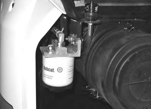
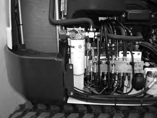
Fuel Filter
Removing Water
Open the tailgate. (See TAILGATE on Page 115.)
Draining The Fuel Tank
See the SERVICE SCHEDULE for the correct service interval. (See SERVICE SCHEDULE on Page 109.)
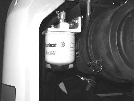
Loosen the drain (Item 1) [Figure 185] at the bottom of the filter to drain water from the filter into a container.
Clean up any spilled fuel.
Replacing Element
Remove the filter (Item 2) [Figure 185]
Clean the area around the filter housing. Put clean oil on the seal of the new filter. Install the fuel filter and hand tighten.
Remove the air from the fuel system. (See Removing Air From The Fuel System on Page 123.)
Warning
AVOID INJURY OR
Death
Diesel fuel or hydraulic fluid under pressure can penetrate skin or eyes, causing serious injury or death. Fluid leaks under pressure may not be visible. Use a piece of cardboard or wood to find leaks. Do not use your bare hand. Wear safety goggles. If fluid enters skin or eyes, get immediate medical attention from a doctor familiar with this injury.
W-2072-EN-0909
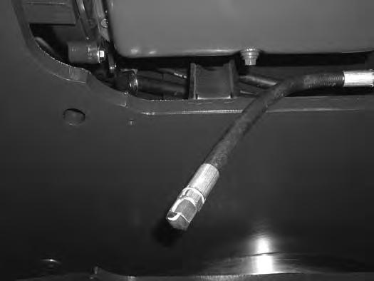
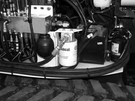
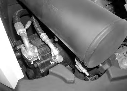
Remove the hose (Item 1) [Figure 186] from the fuel filter. Route the hose to a container.
Squeeze the hand pump (priming bulb) (Item 1) [Figure 187] to start the fuel siphoning from the fuel tank.
Drain the fuel into the container.
Reuse, recycle or dispose of fuel in an environmentally safe manner.
Reinstall the hose (Item 1) [Figure 186] after the fuel is removed from fuel tank.
FUEL SYSTEM (CONT’D)
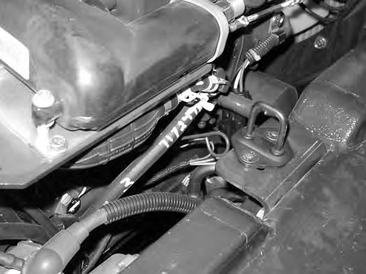
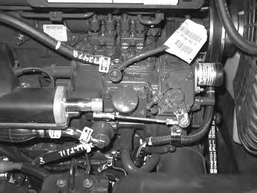
Removing Air From The Fuel System
After replacing the fuel filter or when the fuel tank has run out of fuel, air must be removed from the fuel system before starting the engine.
Warning
Avoid Injury Or Death
Diesel fuel or hydraulic fluid under pressure can penetrate skin or eyes, causing serious injury or death. Fluid leaks under pressure may not be visible. Use a piece of cardboard or wood to find leaks. Do not use your bare hand. Wear safety goggles. If fluid enters skin or eyes, get immediate medical attention from a doctor familiar with this injury.
Open the tailgate. (See TAILGATE on Page 115.)
Open the fuel filter vent (Item 1) [Figure 188] and operate the hand pump (priming bulb) (Item 1) [Figure 189] until the fuel flows from the vent with no air bubbles.
Close the vent (Item 1) [Figure 188]
Clean up any spilled fuel.
Start the engine. It may be necessary to open the vent (Item 2) [Figure 189] (at the fuel injection pump) briefly until the engine runs smoothly.
Engine Lubrication System
Checking And Adding Engine Oil
Check the engine oil after every 8 - 10 hours of operation and before starting the engine. (See SERVICE SCHEDULE on Page 109.)
Figure 190
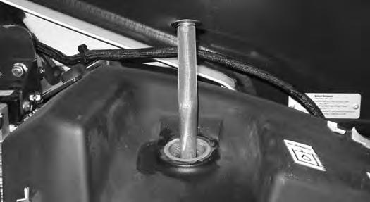
Open the tailgate and remove the dipstick (Item 1) [Figure 190]
Keep the oil level between the marks on the dipstick. Use a good quality motor oil that meets the correct API Ser vice Classification.
Engine Oil Chart
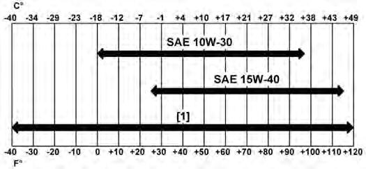
Figure 191
ENGINE OIL RECOMMENDED SAE VISCOSITY NUMBER (LUBRICATION OILS FOR DIESEL ENGINE CRANKCASE)
TEMPERATURE RANGE ANTICIPATED BEFORE NEXT OIL CHANGE (DIESEL ENGINES MUST USE API CLASSIFICATION CJ-4 OR BETTER, OR ACEA E9 OR BETTER)
[1] Bobcat Synthetic Oil – 5W-40
Bobcat engine oils are recommended for use in this machine. If Bobcat engine oil is not available, use a good quality engine oil that meets API Service Classification of CJ-4 or better, or ACEA E9 or better [Figure 191].
Warning
AVOID INJURY OR DEATH
Always clean up spilled fuel or oil. Keep heat, flames, sparks or lighted tobacco away from fuel and oil. Failure to use care around combustibles can cause explosion or fire.
W-2103-0508
ENGINE LUBRICATION SYSTEM (CONT’D)
Removing And Replacing Oil And Filter
See the SERVICE SCHEDULE for the service interval for replacing the engine oil and filter. (See SERVICE SCHEDULE on Page 109.)
Run the engine until it is at operating temperature. Stop the engine.
Open the tailgate. (See TAILGATE on Page 115.)
192
If equipped with the optional air deflector, remove the four bolts and the air deflector to access the drain hose (Item 1) [Figure 192]
Remove the drain hose (Item 1) from the storage clamp (Item 2) [Figure 192]
193
Place a container under the excavator. Remove the drain plug (Item 1) [Figure 193] from the drain hose.
Recycle or dispose of used oil in an environmentally safe manner.
194
Remove the oil filter (Item 1) [Figure 194] and clean the filter housing surface.
Use a genuine Bobcat replacement filter. Put clean oil on the filter gasket. Install the filter and hand tighten.
Install and tighten the drain plug (Item 1) [Figure 193]
Put the drain hose (Item 1) back into the storage clamp (Item 2) [Figure 192]
195
Remove the fill cap (Item 1) [Figure 195].
Put oil in the engine. (See ENGINE LUBRICATION SYSTEM on Page 124.) and (See Capacities on Page 169.)
Install the fill cap (Item 1) [Figure 195]
Start the engine and let it run for several minutes.
Stop the engine. Check for leaks at the oil drain plug and the oil filter. Check the oil level.
Add oil as needed if it is not at the top mark on the dipstick.
Engine Cooling System
Check the cooling system every day to prevent over-heating, loss of performance or engine damage. (See SERVICE SCHEDULE on Page 109.)
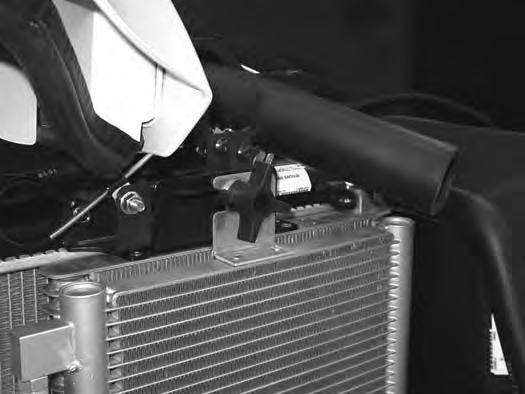
Cleaning
Open the right side cover. (See RIGHT SIDE COVER on Page 116.)
NOTE:Allow the cooling system and engine to cool before servicing or cleaning the cooling system.
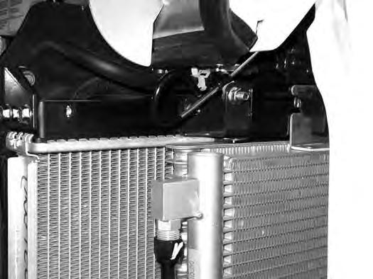
Loosen the knob (Item 1) [Figure 196]. Slide the knob towards the rear of the machine.
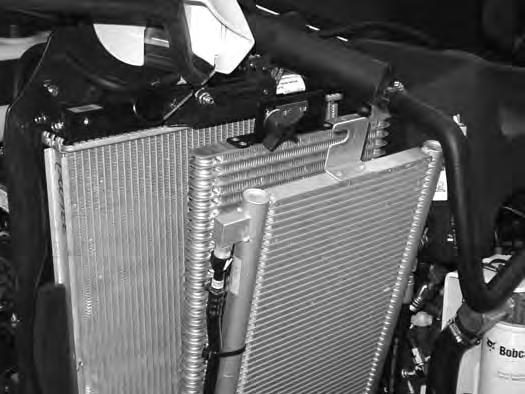
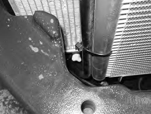
Use air pressure or water pressure to clean the radiator (Item 1), oil cooler (Item 2) and condenser (Item 3) [Figure 198] (if equipped). Be careful not to damage fins when cleaning.
Position the knob (Item 1) so it fits into the radiator mount (Item 3) and the condenser mount (Item 2) [Figure 197] (if equipped).
Slide the knob (Item 1) toward the front of the machine until it is fully seated in the slots of the mounting brackets. Tighten the knob (Item 1) [Figure 196]. Be careful not to damage fins.
Slide the knob (Item 1) out of the condenser mount (Item 2) (if equipped) and the radiator mounting bracket (Item 3) [Figure 197]. Be careful not to damage fins.
ENGINE COOLING SYSTEM (CONT’D)
Checking Level
Warning
AVOID BURNS
Do not remove radiator cap when the engine is hot. You can be seriously burned.
W-2070-1203
Warning
AVOID INJURY OR DEATH
Wear safety glasses to prevent eye injury when any of the following conditions exist:
•When fluids are under pressure.
•Flying debris or loose material is present.
•Engine is running.
•Tools are being used.
W-2019-0907
Open the tailgate. (See TAILGATE on Page 115.)
Figure 199
Important
AVOID ENGINE DAMAGE
Always use the correct ratio of water to antifreeze.
Too much antifreeze reduces cooling system efficiency and may cause serious premature engine damage.
Too little antifreeze reduces the additives which protect the internal engine components; reduces the boiling point and freeze protection of the system.
Always add a premixed solution. Adding full strength concentrated coolant can cause serious premature engine damage.
I-2124-0497
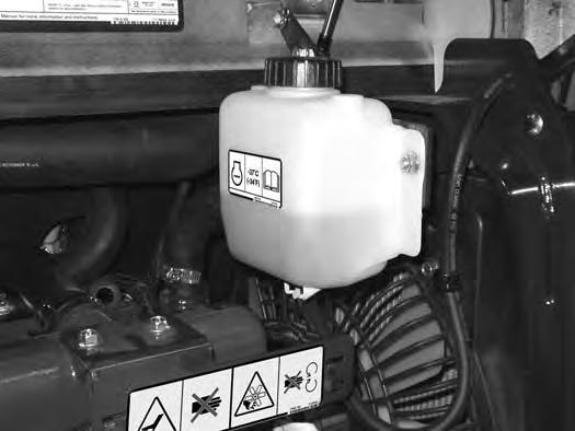
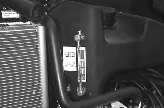
Check the coolant level in the coolant recovery tank (Item 1) [Figure 199]
The coolant level must be between the MIN and MAX marks on the coolant recovery tank when the engine is cold.
NOTE: The cooling system is factory filled with propylene glycol (purple colour). DO NOT mix propylene glycol with ethylene glycol.
ENGINE COOLING SYSTEM (CONT’D)
Removing And Replacing Coolant
See the SERVICE SCHEDULE for correct service inter vals. (See SERVICE SCHEDULE on Page 109.)
Stop the engine. Open the tailgate. (See TAILGATE on Page 115.)
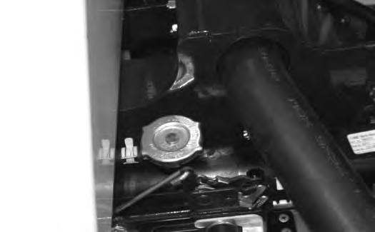
Warning
AVOID BURNS
Do not remove radiator cap when the engine is hot. You can be seriously burned.
When the engine is cool, loosen and remove the radiator cap (Item 1) [Figure 200]
After all the coolant is removed, close both drain valves. Recycle or dispose of the used coolant in an environmentally safe manner.
Mix the coolant in a separate container. (See ENGINE COOLING SYSTEM on Page 126.) and (See Capacities on Page 169.)
NOTE: The cooling system is factory filled with propylene glycol (purple colour). DO NOT mix propylene glycol with ethylene glycol.
The correct mixture of coolant to provide a -37°C (-34°F) freeze protection is 5 L propylene glycol mixed with 4,4 L of water OR 1 U.S. gal propylene glycol mixed with 3.5 qt of water.
Add premixed coolant; 47% water and 53% propylene glycol to the recovery tank if the coolant level is low.
Add premixed coolant until the level is correct.
Run the engine until it is at operating temperature. Stop the engine. Check the coolant level and add as needed. Be sure the radiator cap is tight.
Add coolant to the recovery tank as needed. Close the tailgate.
Description
Figure 203
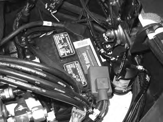
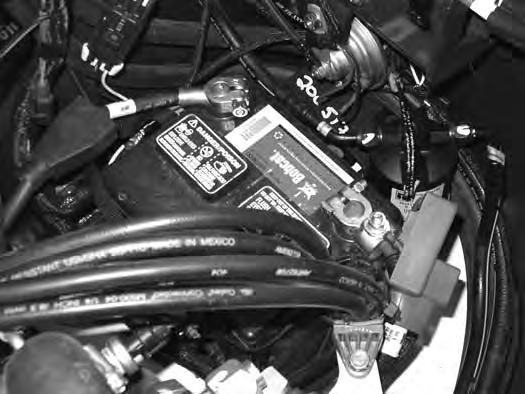
The excavator has a 12 volt, negative earth electrical system. The electrical system is protected by fuses located under the right side cover of the excavator (Item 1) [Figure 203]. The fuses will protect the electrical system when there is an electrical overload. The reason for the overload must be found and corrected before starting the engine again.
The battery cables must be clean and tight. Check the electrolyte level in the battery. Add distilled water as needed. Remove acid or corrosion from the battery and cables with a sodium bicarbonate and water solution.
Put Battery Saver P/N 6664458 or grease on the battery terminals and cable ends to prevent corrosion.
Warning
AVOID INJURY OR DEATH
Batteries contain acid which burns eyes and skin on contact. Wear goggles, protective clothing and rubber gloves to keep acid off body.
In case of acid contact, wash immediately with water. In case of eye contact get prompt medical attention and wash eye with clean, cool water for at least 15 minutes.
If electrolyte is taken internally drink large quantities of water or milk! DO NOT induce vomiting. Get prompt medical attention.
W-2065-0807
Fuse And Relay Location / Identification
A decal is inside the fuse cover to show location and amp ratings.
Remove the cover to check or replace the fuses and relays.
The location and sizes are shown in [Figure 204]
Always replace fuses using the same type and capacity.
ELECTRICAL SYSTEM (CONT’D)
Fuse And Relay Location / Identification (Cont’d)

ELECTRICAL SYSTEM (CONT’D)
Shut-Off Switch
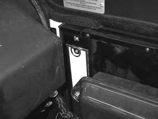
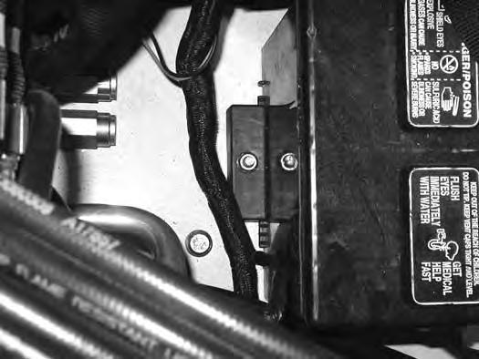
Open the right side cover. (See RIGHT SIDE COVER on Page 116.)
Figure 205
The shut-off switch (Item 1) [Figure 205] is located under the right side cover below the fuse panel.
Rotate the switch (Item 1) [Figure 205] anticlockwise to turn the switch to the OFF position, clockwise to turn to the ON position.
Battery Maintenance
Open the right side cover. (See RIGHT SIDE COVER on Page 116.)
Figure 206
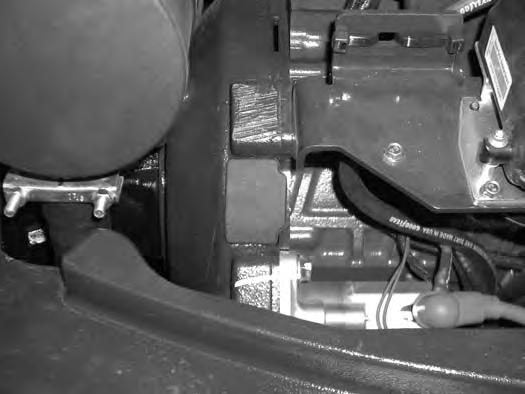
The battery (Item 1) [Figure 206] is located in the front of the right side upperstructure.
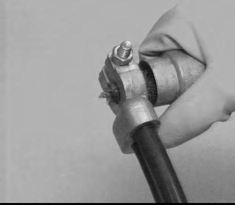
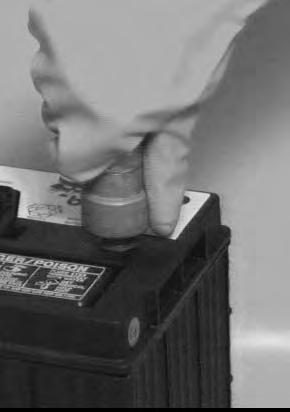
The battery cables must be clean and tight [Figure 207] Remove acid or corrosion from the battery and cables using a sodium bicarbonate and water solution. Cover the battery terminals and cable ends with battery saver grease to prevent corrosion.
Check for broken or loose connections.
If the battery cables are removed for any reason, disconnect the negative (-) cable first. When installing the battery cables, make the last connection the negative (-) cable to the battery.
The original equipment battery is maintenance free. If a replacement battery is installed, check the electrolyte level in the battery.
If the electrolyte level is lower than 13 mm (0.50 in) above the plates, add distilled water only.
Warning
Avoid Injury Or Death
Batteries contain acid which burns eyes and skin on contact. Wear goggles, protective clothing and rubber gloves to keep acid off body.
In case of acid contact, wash immediately with water. In case of eye contact get prompt medical attention and wash eye with clean, cool water for at least 15 minutes.
If electrolyte is taken internally drink large quantities of water or milk! DO NOT induce vomiting. Get prompt medical attention.
ELECTRICAL SYSTEM (CONT’D)
Using A Booster Battery (Jump Starting)
Important
If jump starting the excavator from a second machine:
When jump starting the excavator from a battery installed in a second machine, make sure the engine is NOT running while using the glow plugs. High voltage spikes from a running machine can burn out the glow plugs.
I-2060-0906
If it is necessary to use a booster battery to start the engine, BE CAREFUL! There must be one person in the operator’s seat and one person to connect and disconnect the battery cables.
Be sure the key switch is OFF. The booster battery must be 12 volt.
Open the tailgate. (See TAILGATE on Page 115.)
Important
Damage to the alternator can occur if:
•Engine is operated with battery cables disconnected.
•Battery cables are connected when using a fast charger or when welding on the excavator. (Remove both cables from the battery.)
•Extra battery cables (booster cables) are connected wrong.
I-2223-0903
Warning
AVOID INJURY OR DEATH
Batteries contain acid which burns eyes and skin on contact. Wear goggles, protective clothing and rubber gloves to keep acid off body.
In case of acid contact, wash immediately with water. In case of eye contact get prompt medical attention and wash eye with clean, cool water for at least 15 minutes.
If electrolyte is taken internally drink large quantities of water or milk! DO NOT induce vomiting. Get prompt medical attention.
W-2065-0807
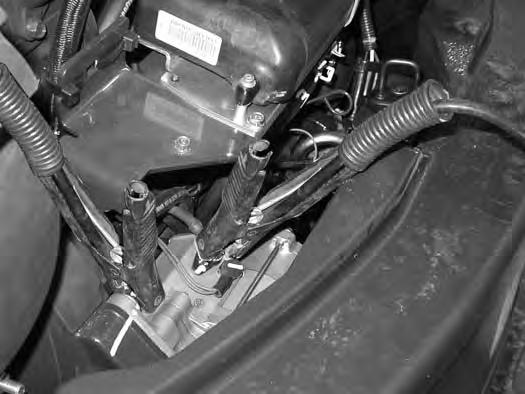
Connect one end of the first cable to the positive (+) terminal of the booster battery. Connect the other end of the same cable to the positive (+) terminal (Item 1) [Figure 208] of the excavator starter.
Connect one end of the second cable to the negative (-) terminal of the booster battery. Connect the other end of the same cable to the starter mounting bolt (Item 2) [Figure 208].
Start the engine. After the engine has started, remove the earth (-) cable first (Item 2) [Figure 208]
Disconnect the cable from the excavator starter (Item 1) [Figure 208]
NOTE:(See Cold Temperature Starting on Page 67.)
ELECTRICAL SYSTEM (CONT’D)
Removing And Installing The Battery
Open the right side cover. (See RIGHT SIDE COVER on Page 116.)
Warning
Avoid Injury Or Death
Batteries contain acid which burns eyes and skin on contact. Wear goggles, protective clothing and rubber gloves to keep acid off body.
In case of acid contact, wash immediately with water. In case of eye contact get prompt medical attention and wash eye with clean, cool water for at least 15 minutes.
If electrolyte is taken internally drink large quantities of water or milk! DO NOT induce vomiting. Get prompt medical attention.
Disconnect the negative (-) cable (Item 1) [Figure 209] first.
Disconnect the positive (+) cable (Item 2) [Figure 209]
Remove the bolt (Item 1) [Figure 210] and remove the hold down clamp.
Remove the battery.
Always clean the terminals and the cable ends, even when installing a new battery.
Connect the negative (-) cable last to prevent sparks.
Connect and tighten the battery cables.
Install and tighten the battery hold down.
Hydraulic System
Checking And Adding Hydraulic Oil
Put the machine on a flat level surface.
Retract the arm and bucket cylinders, put the bucket on the ground and lower the blade. Stop the engine. Open the right side cover. (See RIGHT SIDE COVER on Page 116.)
Figure 212
Park the machine in the position shown [Figure 211] (The preferred method is to check the hydraulic oil when it is cold.)
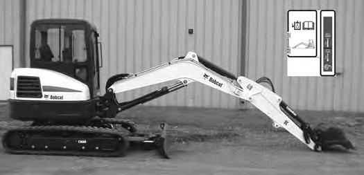
Check the hydraulic oil level, it must be visible in the sight gauge (Item 1) [Figure 211]. The decal on the hydraulic tank shows the correct fill level.
A - Correct Oil Level COLD (Preferred)
B - Correct Oil Level HOT (Optional)
Clean the surface around the reservoir cap and remove the cap from the reservoir (Item 2) [Figure 211]
Warning
Avoid Injury Or Death
Always clean up spilled fuel or oil. Keep heat, flames, sparks or lighted tobacco away from fuel and oil. Failure to use care around combustibles can cause explosion or fire.
W-2103-0508
Check the condition of the fill strainer screen (Item 1) [Figure 212]. Clean or replace as necessary.
Be sure the screen is installed before adding fluid. Add the correct fluid to the reservoir until it is visible in the sight gauge. (See HYDRAULIC SYSTEM on Page 134.)
Check the cap and clean as necessary. Replace the cap if damaged.
Install the cap.
Close the right side cover and tailgate.
Hydraulic / Hydrostatic Fluid Chart
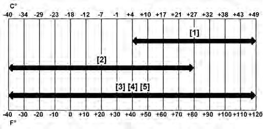
Figure 213
HYDRAULIC / HYDROSTATIC FLUID RECOMMENDED ISO VISCOSITY GRADE (VG) AND VISCOSITY INDEX (VI) TEMPERATURE
Install the oil fill cap.
HYDRAULIC SYSTEM (CONT’D)
Removing And Replacing Hydraulic Filters
Warning
AVOID INJURY OR DEATH
Always clean up spilled fuel or oil. Keep heat, flames, sparks or lighted tobacco away from fuel and oil. Failure to use care around combustibles can cause explosion or fire.
W-2103-0508
Hydraulic Filter
See the SERVICE SCHEDULE for the correct service interval. (See SERVICE SCHEDULE on Page 109.)
Remove the hydraulic filter (Item 1) [Figure 215]
Clean the housing where the filter gasket makes contact. Put clean hydraulic fluid on the gasket. Install the new filter and hand tighten only. Use a genuine Bobcat replacement filter.

Open the right side cover. (See RIGHT SIDE COVER on Page 116.)
For easier access to change the hydraulic filter, remove the lower right side panel.
Remove the four bolts (Item 1) from the side panel (Item 2) [Figure 214]. Remove the side panel.
HYDRAULIC SYSTEM (CONT’D)
Removing And Replacing Hydraulic Filters (Cont’d)
Warning
AVOID
Injury Or Death
Always clean up spilled fuel or oil. Keep heat, flames, sparks or lighted tobacco away from fuel and oil. Failure to use care around combustibles can cause explosion or fire.
W-2103-0508
Case Drain Filter
See the SERVICE SCHEDULE for the correct service interval. (See SERVICE SCHEDULE on Page 109.)
The case drain filter is located in the right front corner of the excavator.
Open the right side cover. (See RIGHT SIDE COVER on Page 116.)
For easier access to change the case drain filter, remove the lower right side panel.
Remove the four bolts (Item 1) from the side panel (Item 2) [Figure 214]. Remove the side panel.
Figure 216
P-97141
Remove the case drain filter (Item 1) [Figure 216]
Clean the housing where the filter gasket makes contact.
HYDRAULIC SYSTEM (CONT’D)
Removing And Replacing Hydraulic Fluid
See the SERVICE SCHEDULE for the correct service interval. (See SERVICE SCHEDULE on Page 109.)
Warning
AVOID INJURY OR DEATH
Diesel fuel or hydraulic fluid under pressure can penetrate skin or eyes, causing serious injury or death. Fluid leaks under pressure may not be visible. Use a piece of cardboard or wood to find leaks. Do not use your bare hand. Wear safety goggles. If fluid enters skin or eyes, get immediate medical attention from a doctor familiar with this injury.
W-2072-EN-0909
Retract the arm and bucket cylinders, lower the bucket to the ground. Stop the engine.
Open the tailgate. (See TAILGATE on Page 115.)
Reposition the drain hose out the bottom of the upperstructure and remove the cap (Item 1) [Figure 218]
Drain the fluid into a container.
Recycle or dispose of the fluid in an environmentally safe manner.
Install the cap (Item 1) [Figure 218] and position the drain hose back to the storage position (Item 1) [Figure 217]
Add fluid to the reservoir. (See HYDRAULIC SYSTEM on Page 134.)
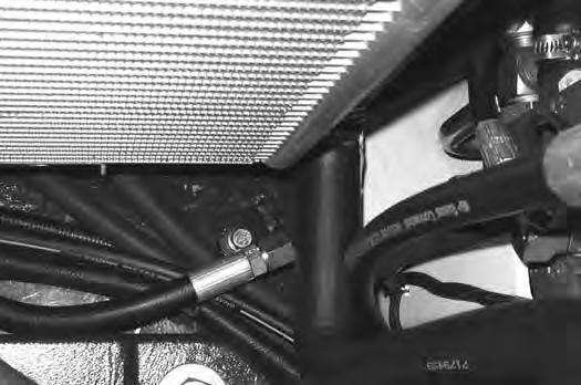
The hydraulic oil drain hose (Item 1) [Figure 217] is located below the oil cooler in the right rear corner of the upperstructure.
With the engine OFF, loosen the hose (Item 1) [Figure 219] on the hydraulic pump until all air is purge from the system. Tighten the hose after a steady stream of hydraulic fluid, free of any air bubbles, drains from the hose. DO NOT RUN THE MACHINE WITH THE HOSE LOOSE.
Start the engine and operate the machine through the hydraulic functions. Stop the engine. Check the fluid level and add as needed.
Spark Arrester Muffler
Cleaning Procedure
See the SERVICE SCHEDULE for the correct service interval. (See SERVICE SCHEDULE on Page 109.)
Warning
Avoid Injury Or Death
When an engine is running in an enclosed area, fresh air must be added to avoid concentration of exhaust fumes. If the engine is stationary, vent the exhaust outside. Exhaust fumes contain odorless, invisible gases which can kill without warning.
W-2050-0807
Warning
Stop engine and allow the muffler to cool before cleaning the spark chamber. Wear safety goggles. Failure to obey can cause serious injury.
W-2011-1285
Warning
Never use machine in atmosphere with explosive dust or gases or where exhaust can contact flammable material. Failure to obey warnings can cause injury or death.
W-2068-1285
Warning
When the engine is running during service, the steering levers must be in neutral.
Failure to do so can cause injury or death.
W-2203-0595
Do not operate the excavator with a defective exhaust system.
Stop the engine. Open the tailgate. (See TAILGATE on Page 115.)
Remove the plug (Item 1) [Figure 220] from the bottom of the muffler.
Start the engine and run for about 10 seconds while a second person, wearing safety glasses, holds a piece of wood over the outlet of the muffler. The carbon deposits will be forced out of the muffler plug hole (Item 1) [Figure 220]
Stop the engine. Install and tighten the plug.
Close the tailgate.
Important
This machine is factory equipped with a spark arrester exhaust system.
The spark arrester muffler, if equipped, must be cleaned to keep it in working condition. The spark arrester muffler must be serviced by dumping the spark chamber every 100 hours of operation.
On some models, the turbocharger functions as the spark arrester and must operate correctly for proper spark arrester function.
If this machine is operated on flammable forest, brush, or grass covered land, a spark arrester attached to the exhaust system may be required and must be maintained in working order. Refer to local laws and regulations for spark arrester requirements. I-2284-EN-0909
Track Tension
NOTE: The wear of the pins and bushings on the undercarriage vary with the working conditions and the different types of soil conditions. It is necessary to inspect track tension and maintain the correct tension. See SERVICE SCHEDULE for the correct service interval. (See SERVICE SCHEDULE on Page 109.)
AVOID INJURY
Keep fingers and hands out of pinch points when checking the track tension.
W-2142-0903
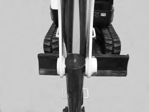
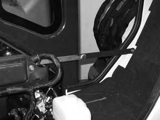
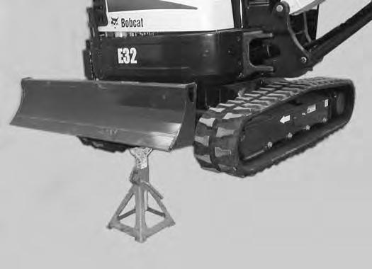
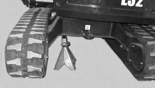
Raise one side of the machine (Approximately four inches) using the boom and arm.
Raise the blade fully and install jackstands under the blade and track frame (Item 1) [Figure 221]. Lower the boom until all machine weight is on the jackstands.
Stop the engine.
TRACK TENSION (CONT’D)
Adjusting (Cont’d)
Rubber Track Clearance
Figure 222
10 - 15 mm (0.39 - 0.59 in)
Steel Track Clearance
Figure 224
10 - 15 mm
- 0.59 in)
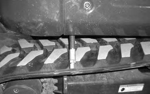
Measure the clearance at the middle track roller. Do not get fingers into pinch points between the track and the track roller. Use a bolt or a dowel of the appropriate size to check the gap between the contact edge of the roller and the top edge of the track guide [Figure 222] and [Figure 223]
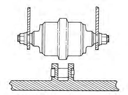
Rubber Track Clearance - 10 - 15 mm (0.39 - 0.59 in).
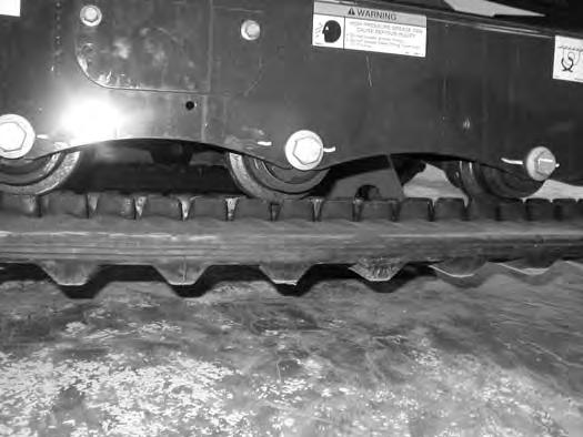
Measure the track clearance at the middle track roller. Do not get fingers into pinch points between the track and the track roller. Us a bolt or dowel of the appropriate size to check the gap between the contact edge of the roller and the top edge of the track guide [Figure 224]
Steel Track Clearance - 17,3 - 30 mm (0.68 - 1.18 in).
TRACK TENSION (CONT’D)
Adjusting (Cont’d)
Warning
HIGH PRESSURE GREASE CAN CAUSE SERIOUS INJURY •Do not loosen the track tension fitting more than 1 - 1/2 turns.
W-2994-0515
With Bleed Screw and Track Tension Fitting
Figure 226
Add grease to the track tension fitting (Item 1) [Figure 226] until the track tension is correct.
Figure 227
The tension removal tool (P/N 6675936) is available and recommended to direct the flow of grease to aid in cleanup. Always dispose of the grease in an environmentally friendly manor.
Use tool 6675936 (Item 1) [Figure 227] to loosen the bleed fitting (Item 2) [Figure 226] to release tension from the track. Do not loosen the bleed fitting more than 1-1/2 turns.
The tool is sized to fit the bleed fitting (Item 2) [Figure 226].
NOTE: Do not loosen the track tension fitting (Item 1) [Figure 226].
Repeat the procedure for the opposite side.
With One Piece - Track Tension Fitting
Figure 228
Add grease to the track tension fitting (Item 1) [Figure 228] until the track tension is correct.
Figure 229
The tension removal tool (P/N 7277225) is available and recommended to direct the flow of grease to aid in cleanup. Always dispose of the grease in an environmentally friendly manor.
Use tool 7277225 (Item 1) [Figure 229] to loosen the track tension fitting (Item 1) [Figure 228] to release tension from the track.
The tool is sized to fit the one piece track tension fitting (Item 1) [Figure 228]
NOTE: Do not loosen the track tension fitting (Item 1) [Figure 228] more than 1-1/2 turns.
Installation: Tighten the track tension fitting to 24 - 30 N•m (18 - 22 ft-lb) torque.
Repeat the procedure for the opposite side.
Travel Motor
Checking And Adding Oil
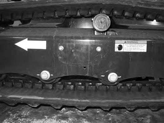
Figure 230
Park the excavator on a level surface with the plugs (Items 1 and 2) [Figure 230] positioned as shown.
Remove the plug (Item 1) [Figure 230]. The lube level must be at the bottom edge of the hole.
Add lubricant (SAE 90W) through the hole (Item 1) [Figure 230] if the lube level is low.
Repeat the procedure for the opposite travel motor.
Removing And Replacing Oil
See the SERVICE SCHEDULE for the correct service interval. (See SERVICE SCHEDULE on Page 109.)
Warning
Avoid Injury Or Death
Always clean up spilled fuel or oil. Keep heat, flames, sparks or lighted tobacco away from fuel and oil. Failure to use care around combustibles can cause explosion or fire.
Park the excavator on a level surface with plugs (Items 1 and 2) [Figure 230] positioned as shown. Remove both plugs and drain the lubricant into a container.
Install the bottom plug (Item 2). Add lubricant (SAE 90W) through the plug hole (Item 1) [Figure 230] until the lube level is at the bottom edge of the hole. (See Capacities on Page 169.)
Install the plug (Item 1) [Figure 230]
Repeat the procedure for the opposite travel motor.
Alternator Belt
Belt Adjustment
The alternator belt is a special maintenance free type that is pretensioned over the pulleys. This belt eliminates the need for a tensioning device and does not require periodic adjustment. Contact your Bobcat dealer for replacement parts.
Belt Replacement
Stop the engine and open the tailgate. (See TAILGATE on Page 115.)
NOTE:If the machine is equipped with air conditioning, the compressor belt will need to be removed before the alternator belt can be removed.
The engine will need to be rotated by hand to remove the belt. To access the flywheel, remove the plug (Item 1) [Figure 232] from the flywheel housing. (A pry bar will be needed to rotate the flywheel to assist in belt removal and installation.)
Remove the air conditioning compressor belt (if equipped). (See AIR CONDITIONING COMPRESSOR BELT on Page 145.)
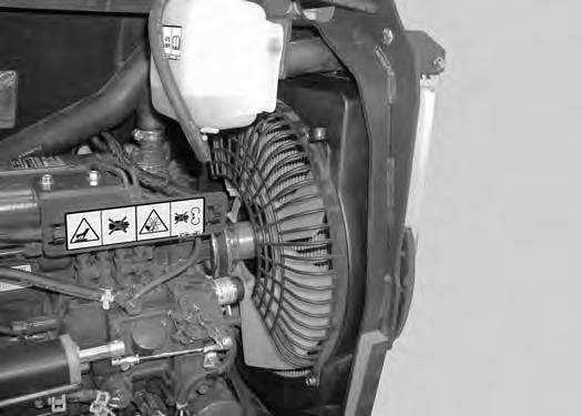
Remove the three bolts (Item1) and remove the fan guard (Item 2) [Figure 231]
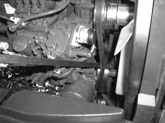
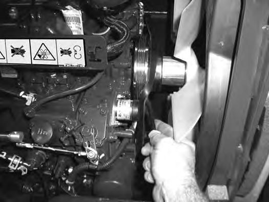
Use a pry bar between the belt and the crankshaft pulley (Item 1) [Figure 233]
Using a pry bar on the flywheel, rotate the engine by hand to push the belt off the crankshaft pulley. Continue to rotate the flywheel until the belt is loose.
ALTERNATOR BELT (CONT’D)
Belt Replacement (Cont’d)
Installation
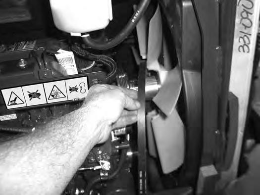
Position the belt (Item 1) [Figure 234] over the fan blades.
Install the belt (Item 1) [Figure 235] over the alternator pulley, the crankshaft pulley and over the fan spacer.
Use a pry bar (Item 2) [Figure 235] to position the belt onto the fan pulley.
Using a pry bar, rotate the flywheel by hand while using the second pry bar (Item 2) [Figure 235] to install the belt over the fan pulley.
Continue to rotate the engine by hand until the belt is fully on the pulleys.
Reinstall the rubber plug (Item 1) [Figure 232]
Install the fan guard (Item 2) with the three bolts (Item1) [Figure 231]
Close the tailgate.
Air Conditioning Compressor Belt
Belt Adjustment
The compressor belt is a special maintenance free type that is pretensioned over the pulleys. This belt eliminates the need for a tensioning device and does not require periodic adjustment. Contact your Bobcat dealer for replacement parts.
Belt Replacement
Stop the engine and open the tailgate. (See TAILGATE on Page 115.)
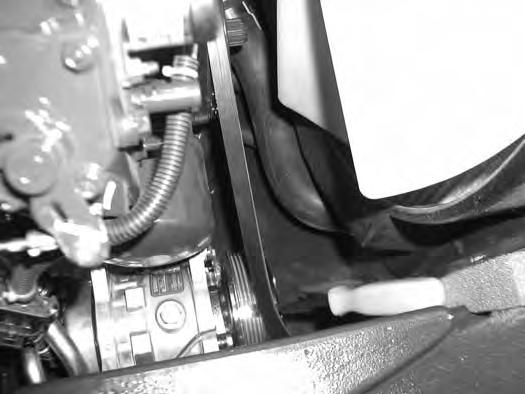
The engine will need to be rotated by hand to remove the belt. To access the flywheel, remove the plug (Item 1) [Figure 236] from the flywheel housing.
Use a pry bar (Item 1) [Figure 237] to push the belt off of the pulley. Using a pry bar on the flywheel, rotate the engine by hand to push the belt off the compressor pulley. Continue to rotate the flywheel until the belt is loose. Remove the belt.
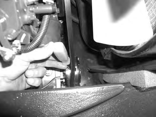
Position the belt (Item 1) [Figure 238] over the crankshaft
Use a pry bar (Item 2) [Figure 238] to position the belt on the pulley while using the second pry bar at the flywheel to rotate the engine by hand.
Continue to rotate the engine by hand until the belt is fully on the pulleys.
Reinstall the rubber plug (Item 1) [Figure 236]
Close the tailgate.
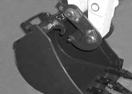
QUICK COUPLER
Quick Coupler And Attachment Inspection And Maintenance
Figure 239
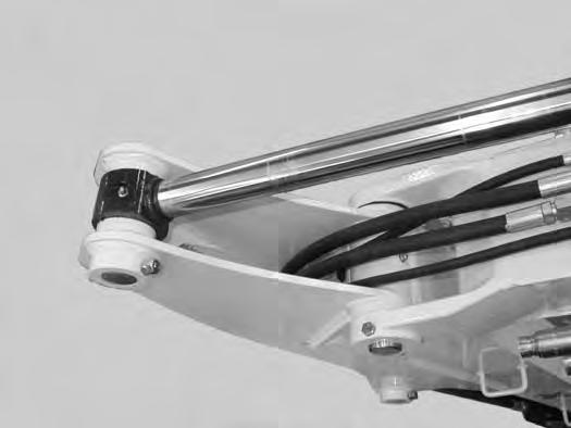
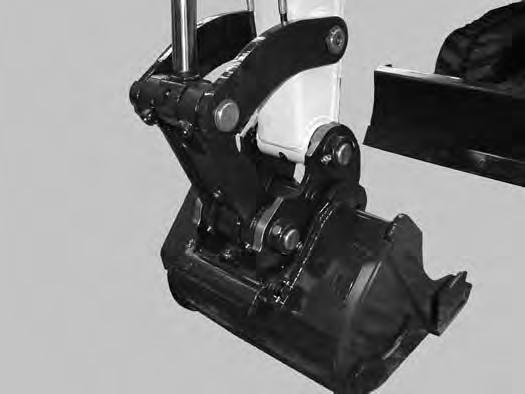
Inspect the quick coupler for wear or damage. Inspect the quick coupler pins (Item 1) and the hooks (Item 2) [Figure 239] (on the attachment) for wear or damage
Repair or replace damaged parts.
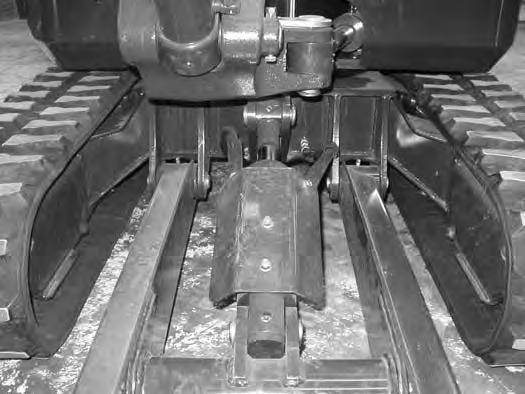
X-CHANGE
Inspection And Maintenance
Figure 240
Inspect the X-Change for wear or damage. Inspect the XChange pins (Item 1) and hooks (Item 2) [Figure 240] (on the attachment) for wear or damage.
Repair or replace damaged parts.
Track
ROLLER AND IDLER LUBRICATION
Procedure
The track rollers and idlers require no maintenance. The bearings are a sealed design.

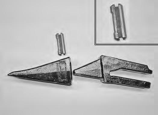
Bucket Teeth Removal And Installation
Warning
Wear safety glasses to prevent eye injury when any of the following conditions exist:
•Pressurised fluids and springs or other stored energy components.
•Flying debris or loose material is present.
•Engine is running.
•Tools are being used.
W-2505-EN-1009
Position the bucket so the bucket teeth are at a 30° angle up from the ground for accessibility to the teeth.
Lower the boom until the bucket is fully on the ground.
Stop the engine and exit the excavator.
The retaining pin (Item 1) must be installed as shown [notch (Item 2) to the front] for proper fit and tooth retention. The side of the tooth point (Item 3) [Figure 241] also shows the correct orientation of the retaining pin.
Installation: Position the new tooth point on the shank and install a new retaining pin. Install the retaining pin until it is flush with the top of the point.
LUBRICATION OF THE HYDRAULIC EXCAVATOR
Lubrication Locations
Lubricate the excavator as specified in the SERVICE SCHEDULE for the best performance of the machine. (See SERVICE SCHEDULE on Page 109.)
Always use a good quality lithium based multipurpose grease when lubricating the machine. Apply the lubricant until extra grease shows.
Lubricate the following locations on the excavator EVERY 8 - 10 HOURS:
Cylinder Rod End (1) [Figure 242]
LUBRICATION OF THE HYDRAULIC EXCAVATOR (CONT’D)
Lubrication Locations (Cont’d)
14.Bucket
15.Bucket
16.Arm