18 minute read
PRE-STARTING PROCEDURE (CONT’D)


Control Console
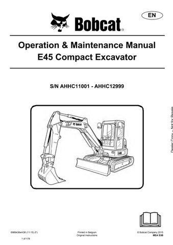
Mirror Adjustment
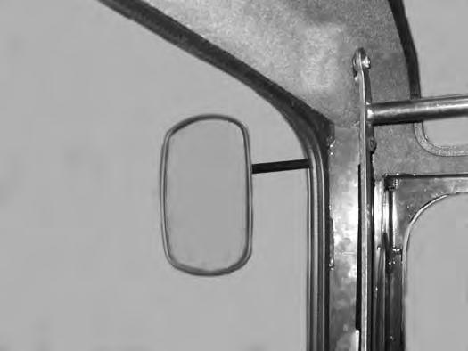
NOTE:There is a control lock sensor in the left console which deactivates the hydraulic control levers (joysticks) and the traction drive system when the control console is raised. The console must be in the locked down position for the hydraulic control levers (joysticks) and traction system to operate.
NOTE:If the control lock sensor does not deactivate the control levers and traction system when console is raised, see your Bobcat dealer for service.
STARTING THE ENGINE Key Switch
Warning
AVOID INJURY OR DEATH
•Fasten seat belt, start and operate only from the operator’s seat.
•Never wear loose clothing when working near machine.
W-2135-1108
Perform the PRE-STARTING PROCEDURE. (See PRESTARTING PROCEDURE on Page 62.)
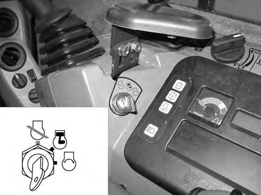
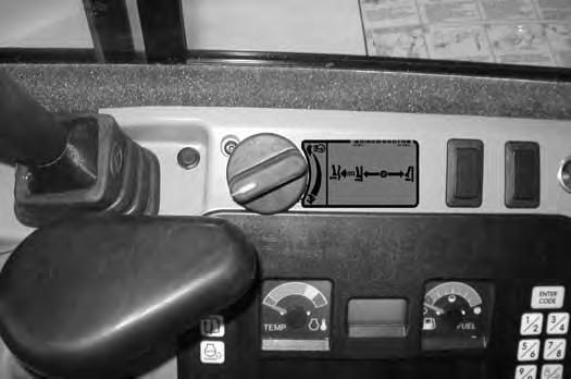
Turn the key (Item 1) [Figure 75] to the ON position. If preheating is required, the glow plugs will automatically cycle and the remaining preheat time (in seconds) will show in the data display screen. (Preheat icon will be ON).
Turn the key to START and release the key when the engine starts. It will return to the ON position [Figure 75]
Stop the engine if the warning lights and alarm do not go OFF. Check for the cause before starting the engine again.
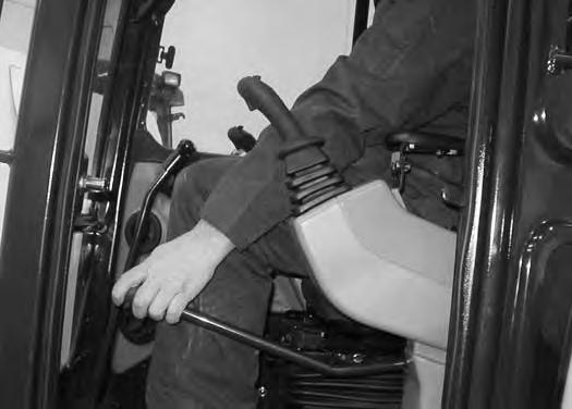
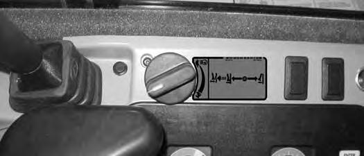
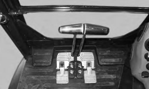
Put control levers (Item 1) [Figure 73] in the NEUTRAL position.
74
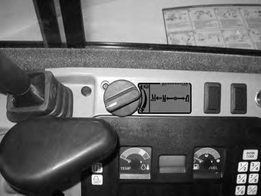
Turn the engine speed control dial (Item 1) [Figure 74] anticlockwise to low idle.
Important
Do not engage the starter for longer than 15 seconds at a time. Longer use can damage the starter by overheating. Allow starter to cool for one minute before using starter again.
I-2034-0700
Turn the key switch OFF to stop the engine.
Warning
AVOID INJURY OR DEATH
When an engine is running in an enclosed area, fresh air must be added to avoid concentration of exhaust fumes. If the engine is stationary, vent the exhaust outside. Exhaust fumes contain odorless, invisible gases which can kill without warning.
W-2050-0807
Warning
AVOID SERIOUS INJURY OR DEATH
•Engines can have hot parts and hot exhaust gas. Keep flammable material away.
•Do not use machines in atmosphere containing explosive dust or gases.
W-2051-0212
STARTING THE ENGINE (CONT’D)
Warning
AVOID INJURY OR DEATH
•Fasten seat belt, start and operate only from the operator’s seat.
•Never wear loose clothing when working near machine.
W-2135-1108
Perform the PRE-STARTING PROCEDURE. (See PRESTARTING PROCEDURE on Page 62.)
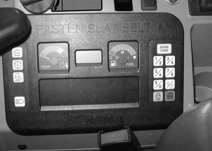
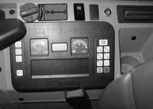
Press [ENTER CODE] Button (Item 1) [Figure 77]. The display will become lighted and there will be two short beeps, CodE will appear on the data display screen.
Use the keypad (Item 2) [Figure 77] to enter the password. For each digit that you enter, a dash will appear on the data display screen. (You have 40 seconds to enter the password or the process will abort and you will need to start over.) If the password was entered correctly, there will be one long beep.
NOTE:If the password was incorrect there will be three short beeps and “Error” will appear on the data display screen. Press the [ENTER CODE] Button again and start over. After three failed attempts, you must wait three minutes to try again.
Press the START Button (Item 3) [Figure 77] and hold it until the engine starts.
Important
Do not engage the starter for longer than 15 seconds at a time. Longer use can damage the starter by overheating. Allow starter to cool for one minute before using starter again.
I-2034-0700
Press the STOP button (Item 4) [Figure 77] to stop the engine.
Stop the engine if the warning lights and alarm do not go OFF.
Check for the cause before starting the engine again.
Password Lockout Feature
See Password Lockout Feature. (See Password Lockout Feature on Page 158.)
STARTING THE ENGINE (CONT’D)
Cold Temperature Starting
Warning
EXPLOSION CAN CAUSE SERIOUS INJURY, DEATH OR SEVERE ENGINE DAMAGE DO NOT use ether or starting fluid with glow plug or air intake heater systems.
W-2071-0415
If the temperature is below freezing, perform the following to make starting the engine easier:
•Replace the engine oil with the correct type and viscosity for the anticipated starting temperature. (See Engine Oil Chart on Page 124.)
•Make sure the battery is fully charged.
•Install an engine heater.
NOTE: If the battery is discharged (but not frozen) a booster battery can be used to jump start the excavator. (See Using A Booster Battery (Jump Starting) on Page 132.).
Figure 78
Rotate the engine speed control dial (Item 1) [Figure 78] clockwise to high idle.

Important
Do not engage the starter for longer than 15 seconds at a time. Longer use can damage the starter by overheating. Allow starter to cool for one minute before using starter again.
Key Switch
Figure 79
Turn the key to the ON position [Figure 79]
Figure 80 key to START.
Release the key when the engine starts, it will return to the ON position.
Stop the engine if the warning lights and alarm do not go off. Check for the cause before starting the engine again.
When the engine speed increases, move the engine speed control dial to idle position until the engine warms.
STARTING THE ENGINE (CONT’D)
Cold Temperature Starting (Cont’d)
Keyless
Follow STARTING PROCEDURE. (See Keyless on Page 66.)
If the preheat icon comes ON, wait for it to go off before pressing the START Button [Figure 80 on Page 67]
The remaining preheat time (in seconds) will count down in the data display screen.
Important
Do not engage the starter for longer than 15 seconds at a time. Longer use can damage the starter by overheating. Allow starter to cool for one minute before using starter again.
I-2034-0700
Important
Machines warmed up with moderate engine speed and light load have longer life.
I-2015-0284
Warning
EXPLOSION CAN CAUSE SERIOUS INJURY, DEATH OR SEVERE ENGINE DAMAGE DO NOT use ether or starting fluid with glow plug or air intake heater systems.
W-2071-0415
Warming The Hydraulic System
Important
When the temperature is below -30°C (-20°F), hydrostatic oil must be warmed before starting. The hydrostatic system will not get enough oil at low temperatures and will be damaged. Park the machine in an area where the temperature will be above -18°C (0°F) if possible.
I-2007-0910
Let the engine run at least 5 minutes to warm the engine and hydraulic fluid before operating the excavator.
STOPPING THE ENGINE AND LEAVING THE EXCAVATOR
Procedure
Stop the machine on level ground. Lower the work equipment and the blade to the ground [Figure 81]
Rotate the engine speed control dial (Item 1) [Figure 82] anticlockwise to low idle.
Run the engine at idle speed for about 5 minutes to allow it to cool.
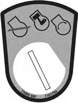
Turn the key switch to STOP [Figure 83] or press the STOP Button (Keyless Panel) (Item 1) [Figure 84]
Disconnect the seat belt. Remove the key from the switch to prevent operation of machine by unauthorised personnel. Raise the control console and exit the machine.
Attachments
Installing And Removing The Attachment (Quick Coupler, Lehnhoff® System)
Installation
NOTE: Installation and removal of the bucket is shown. The procedure is the same for other attachments. Disconnect any hydraulic lines that are operated by hydraulic power before removing any attachments (breaker, auger etc.).
Warning
AVOID INJURY OR DEATH
Never use attachments or buckets which are not approved by Bobcat Company. Buckets and attachments for safe loads of specified densities are approved for each model. Unapproved attachments can cause injury or death.
W-2052-0907
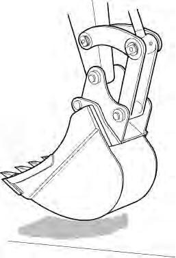
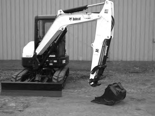
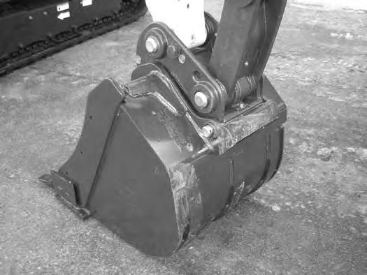
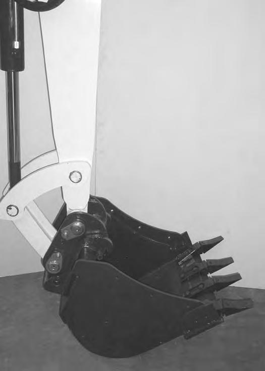
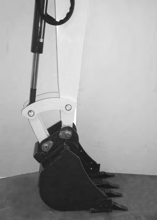
Position the excavator so the excavator arm is above the attachment.
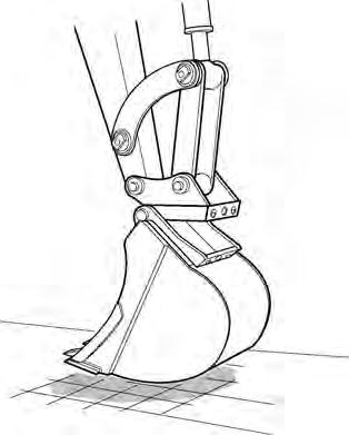
Fully retract the bucket cylinder.
Lower the coupler (Item 1) onto the attachment (Item 2) [Figure 85]
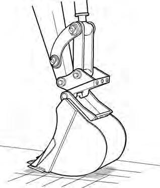
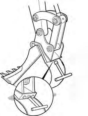
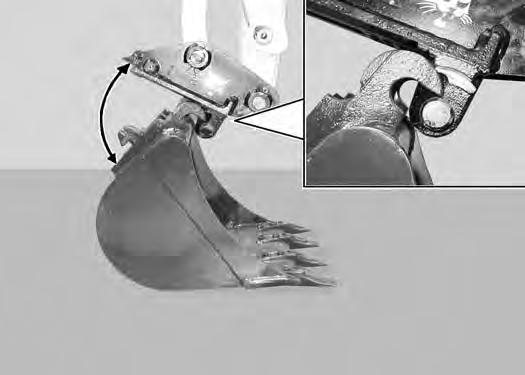
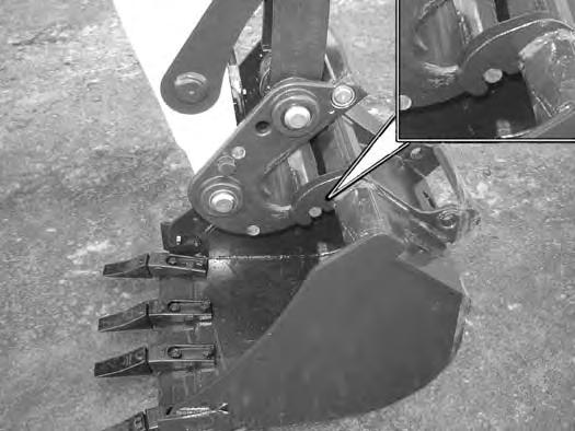
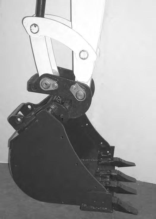
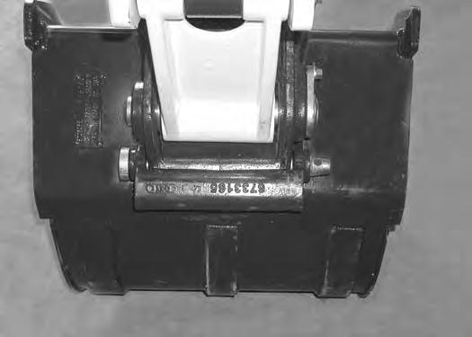
Engage the coupler hooks (Item 1) onto the attachment shaft (Item 2) [Figure 86]
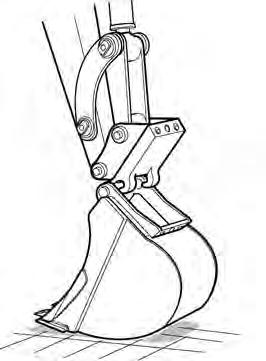
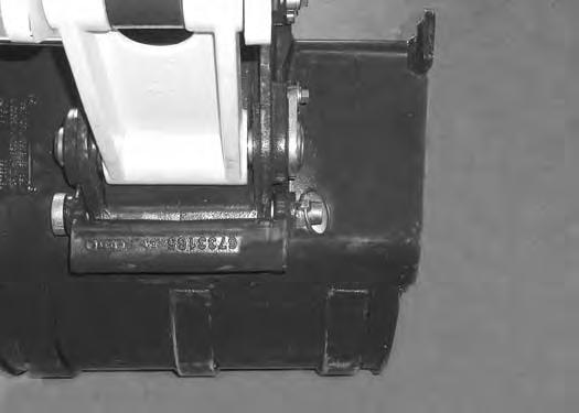
Extend (curl in) the bucket cylinder and slightly raise the boom until the coupler (Item 1) contacts the back of the attachment mount (Item 2) [Figure 87]
ATTACHMENTS (CONT’D)
Installing And Removing The Attachment ((Quick Coupler, Lehnhoff® System) (Cont’d)
Installation (Cont’d)
Engage the parking brake.
Stop the engine and exit the excavator.
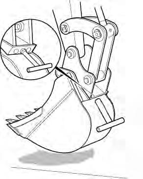
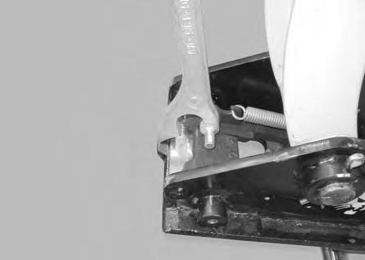
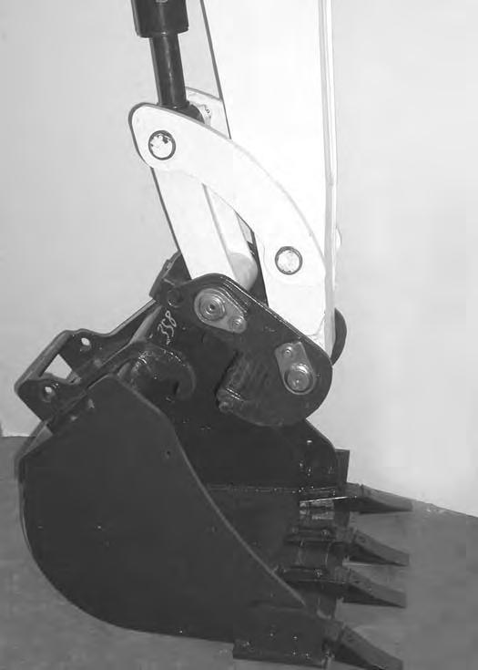
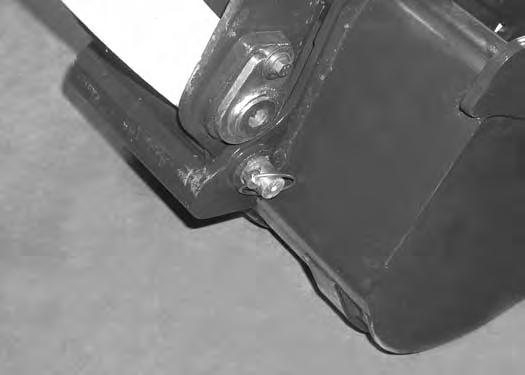
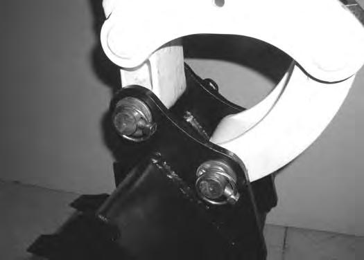
Use the supplied wrench (Item 1) [Figure 88] and turn the locking pins clockwise until they are fully engaged.
Removal
Park the excavator on a level surface.
Install the wrench (Item 1) [Figure 90] on the locking pins and turn anticlockwise until the locking pins are disengaged.
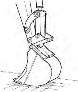
Raise the boom and extend the bucket cylinder until the attachment it is slightly off the ground [Figure 89]
Engage the parking brake.
Stop the engine and exit the excavator.
Enter the excavator, fasten the seat belt and start the engine
Lower the attachment until it is on the ground [Figure 91]
ATTACHMENTS (CONT’D)
Installing And Removing The Attachment (Quick Coupler, Lehnhoff® System) (Cont’d)
Removal (Cont’d)
92
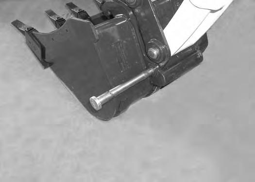
Retract the bucket cylinder to rotate the coupler (Item 1) out of the attachment mount (Item 2) [Figure 92]
Quick Coupler And Attachment Inspection
Inspect the quick coupler for wear or damage. Inspect the attachment shaft and the quick coupler hooks for wear or damage.
Repair or replace damaged parts.
Move the arm out and raise the boom until the quick coupler is clear of the attachment [Figure 93]
ATTACHMENTS (CONT’D)

Installing And Removing The Attachment (Quick Coupler, Klac™ System)
Installation
NOTE: Installation and removal of the bucket is shown. The procedure is the same for other attachments. Disconnect any hydraulic lines that are operated by hydraulic power before removing any attachments (breaker, auger etc.).
Warning
AVOID INJURY OR DEATH
Never use attachments or buckets which are not approved by Bobcat Company. Buckets and attachments for safe loads of specified densities are approved for each model. Unapproved attachments can cause injury or death.
W-2052-0907
Warning
AVOID INJURY
Keep fingers and hands out of pinch points when latching and unlatching the attachment quick coupler.
W-2541-1106
Fully retract the bucket cylinder.
Stop the engine and exit the excavator.
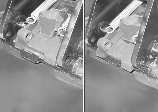
Inspect the quick coupler to make sure the latch is in the unlatched position (Item 1) [Figure 94]
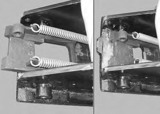
If in the latched position, see [Figure 95] for additional information.
If the latch is in the unlatched position, proceed to [Figure 96].
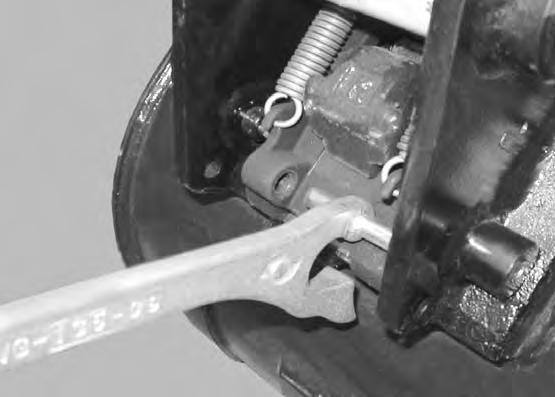
To unlatch the quick coupler, install the tool (Item 1) [Figure 95] and pull the handle. The latch will move completely forward. The latch will lock in the unlatched position.
Enter the excavator, fasten the seat belt and start the engine.
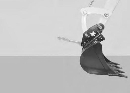
Position the quick coupler (Item 1) to the attachment (Item 2) [Figure 96]
ATTACHMENTS (CONT’D)
Installing And Removing The Attachment (Quick Coupler, Klac™ System) (Cont’d)
Installation (Cont’d)
There must be at least 100 between the quick coupler surface (Item 1) and the attachment mounting surface (Item 2) [Figure 97]. Extend the arm out to get the required angle for proper installation.
NOTE: There must be proper clearance (100 minimum) between the hook (Item 3) and the quick coupler (Item 4) [Figure 97]. Possible damage to the attachment hooks or the quick coupler could occur without proper clearance.
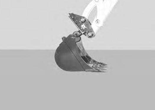
Raise the boom until there is approximately 500 mm (20.0 in) of clearance between the bottom of the attachment and the ground [Figure 99]
Raise the boom and extend the arm until the hooks of the attachment (Item 1) engage the pins (Item 2) of the quick coupler [Figure 98]
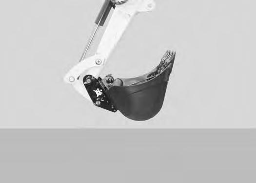
Extend the bucket cylinder (Item 1) [Figure 100] fully.
Lower the attachment until it is flat on the ground.
Stop the engine and exit the excavator.
ATTACHMENTS (CONT’D)
Installing And Removing The Attachment (Quick Coupler, Klac™ System) (Cont’d)
Installation (Cont’d)
101
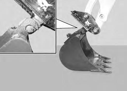
Visually inspect the quick coupler latch (Item 1) to the bucket mount (Item 2) [Figure 101]. The latch must be fully engaged.
Warning
AVOID INJURY
Keep fingers and hands out of pinch points when latching and unlatching the attachment quick coupler.
W-2541-1106
If the latch is not engaged, install the tool (Item 1) in the hole (Item 2) [Figure 102] of the quick coupler and push down to unlatch the quick coupler. Remove the tool. Enter the excavator, fasten the seat belt and start the engine. Raise the attachment 500 mm (20.0 in) off of the ground and fully extend the bucket cylinder. Lower the attachment until it is flat on the ground. Stop the engine and exit the excavator.
Again, visually inspect the quick coupler to make sure the latch (Item 1) [Figure 101] is fully engaged. If it is not fully engaged, remove the attachment and inspect both the quick coupler and the attachment for damage or debris. (See [Figure 117] for Quick Coupler And Attachment Inspection information.)
ATTACHMENTS (CONT’D)
Installing And Removing The Attachment (Quick Coupler, Klac™ System) (Cont’d)
Warning
AVOID INJURY
Keep fingers and hands out of pinch points when latching and unlatching the attachment quick coupler.
W-2541-1106
Position the attachment flat on the ground.
Install the quick coupler tool (Item 1) into the hole (Item 2) [Figure 102] in the quick coupler.
Push down on the tool (Item 1) [Figure 103] to unlock the latch.
Remove the tool.
Enter the excavator, fasten the seat belt and start the engine.
Retract the bucket cylinder fully and lower the boom [Figure 104] until the attachment is on the ground.
Continue to lower the boom and move the arm towards the excavator until the quick coupler is clear of the attachment [Figure 105]
ATTACHMENTS (CONT’D)
Installing And Removing The Attachment (Hydraulic X-Change)
Installation
NOTE: Installation and removal of the bucket is shown. The procedure is the same for other attachments. Disconnect any hydraulic lines that are operated by hydraulic power before removing any attachments (breaker, auger, etc.).
Warning
AVOID INJURY OR DEATH
Never use attachments or buckets which are not approved by Bobcat Company. Buckets and attachments for safe loads of specified densities are approved for each model. Unapproved attachments can cause injury or death.
W-2052-0907
Warning
AVOID INJURY OR DEATH
Both hydraulic pins must be fully extended through the attachment mounting holes. Failure to fully engage the hydraulic pins can allow attachment to come off.
W-2935-0512
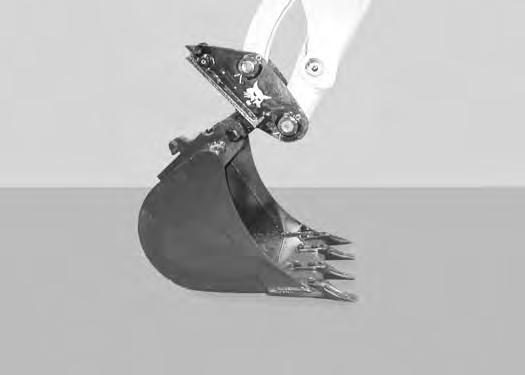
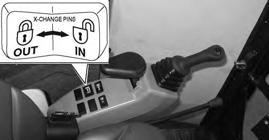
Press and hold the X-Change switch (Item 1) [Figure 107] to the right (IN) to fully retract the hydraulic pins.
Start the engine.
Swing the excavator arm fully to the left [Figure 106] (for better operator visibility when connecting attachments).
Raise the boom until the X-Change pins (Item 1) engage the attachment hooks (Item 2) [Figure 109] on the bucket.
ATTACHMENTS (CONT’D)
Installing And Removing The Attachment (Hydraulic X-Change) (Cont’d)
Installation (Cont’d)
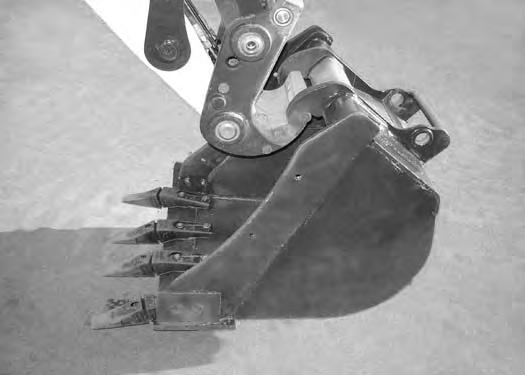
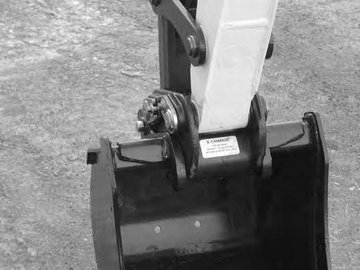
Raise the boom and extend (curl in) the bucket cylinder until the X-Change contacts the back of the attachment [Figure 110]
With the arm vertical, lower the boom until the hooks (Item 1) of the bucket disengage the X-Change pins (Item 2) and the plate (Item 3) [Figure 110] fully engages into the bucket crossmember.
Warning
Keep all bystanders 6 m (20 ft) away from equipment when operating. Contact with moving parts, a trench cave-in or flying objects can cause injury or death.
W-2119-0910
Press and hold the X-Change switch (Item 1) [Figure 111] to the left (OUT) and FULLY EXTEND the hydraulic pins.
112
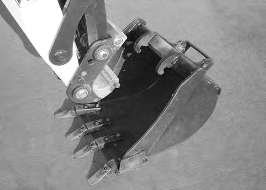
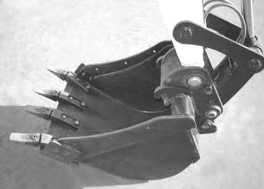
Check that both hydraulic pins (Item 1) [Figure 112] are fully engaged to secure the attachment.
Warning
AVOID INJURY OR DEATH
Both hydraulic pins must be fully extended through the attachment mounting holes. Failure to fully engage the hydraulic pins can allow attachment to come off.
W-2935-0512
ATTACHMENTS (CONT’D)
Installing And Removing The Attachment (Hydraulic X-Change) (Cont’d)
Removal
NOTE: Removal and installation of the bucket is shown. The procedure is the same for other attachments. Disconnect any hydraulic lines that are operated by hydraulic power before removing any attachments (breaker, auger, etc.).
Warning
Keep all bystanders 6 m (20 ft) away from equipment when operating. Contact with moving parts, a trench cave-in or flying objects can cause injury or death.
W-2119-0910
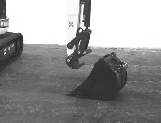
Raise the boom and retract the bucket cylinder until the X-Change pins (Item 1) engage the attachment hooks (Item 2) [Figure 115] on the bucket.
Park the excavator on a flat level surface. Put the attachment on the ground [Figure 113]
Fully retract the bucket cylinder (bucket dump).
Lower the boom and arm until the attachment is on the ground and the X-Change pins are disengaged from the attachment hooks.
Move the arm toward the excavator until the X-Change pins are clear of the attachment [Figure 116]
Press and hold the X-Change switch (Item 1) [Figure 114] on the left console to the right (IN) to FULLY RETRACT the hydraulic pins.
ATTACHMENTS (CONT’D)
Quick Coupler And Attachment Inspection
ATTACHMENTS (CONT’D)
Installing And Removing The Attachment (Pin-On X-Change)
Installation
NOTE: Installation and removal of the bucket is shown. The procedure is the same for other attachments. Disconnect any hydraulic lines that are operated by hydraulic power before removing any attachments (breaker, auger, etc.).
Warning
AVOID INJURY OR DEATH
Never use attachments or buckets which are not approved by Bobcat Company. Buckets and attachments for safe loads of specified densities are approved for each model. Unapproved attachments can cause injury or death.
W-2052-0907
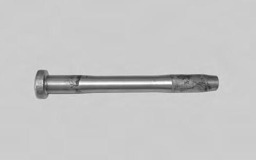
Inspect the pin (Item 1) [Figure 118] for wear or damage. Replace the pin as needed.
Apply a light coat of grease to the ends of the pin (Item 2) [Figure 118]
ATTACHMENTS (CONT’D)
Installing And Removing The Attachment (Pin-On X-Change) (Cont’d)
Installation (Cont’d)
Raise the boom until the pins (Item 1) engage the hooks (Item 2) [Figure 120] on the bucket.
Raise the boom and extend the bucket cylinder until the X-Change contacts the attachment back [Figure 121]
With the arm vertical, lower the boom until the hooks (Item 1) of the bucket disengage the pins (Item 2) of the X-Change and the plate (Item 3) [Figure 121] fully engages in the bucket crossmember.
Warning
Keep all bystanders 6 m (20 ft) away from equipment when operating. Contact with moving parts, a trench cave-in or flying objects can cause injury or death.
W-2119-0910
ATTACHMENTS (CONT’D)
Installing And Removing The Attachment (Pin-On X-Change) (Cont’d)
Installation (Cont’d)
Stop the engine. Turn the start key to the ON position and move both hydraulic control levers to relieve hydraulic pressure.
Install the retainer pin (Item 1) [Figure 123]
Check for proper installation.
Lift the attachment and fully extend and retract the bucket cylinder.
ATTACHMENTS (CONT’D)
Installing And Removing The Attachment (Pin-On X-Change) (Cont’d)
Removal
NOTE: Removal and installation of the bucket is shown. The procedure is the same for other attachments. Disconnect any hydraulic lines that are operated by hydraulic power before removing any attachments (breaker, auger, etc.).
Warning
AVOID INJURY OR DEATH
Never use attachments or buckets which are not approved by Bobcat Company. Buckets and attachments for safe loads of specified densities are approved for each model. Unapproved attachments can cause injury or death.
W-2052-0907
With the engine off, turn the start key to the ON position and move both hydraulic control levers to relieve hydraulic pressure.
ATTACHMENTS (CONT’D)
Installing And Removing The Attachment (Pin-On X-Change) (Cont’d)
Removal (Cont’d)
Warning
AVOID INJURY OR DEATH
Wear safety glasses to prevent eye injury when any of the following conditions exist:
•When fluids are under pressure.
•Flying debris or loose material is present.
•Engine is running.
•Tools are being used.
Start the engine, raise the boom approximately one foot and retract the bucket cylinder until the X-Change pins (Item 1) engage the hooks (Item 2) [Figure 127] on the bucket.
ATTACHMENTS (CONT’D)
Installing And Removing The Attachment (Pin-On X-Change) (Cont’d)
Removal (Cont’d)
ATTACHMENTS (CONT’D)
Installing And Removing The Attachment (Pin-On Attachment)
Installation
Warning
AVOID INJURY OR DEATH
Stop the machine on a firm flat surface. When removing or installing attachments (such as a bucket), always have a second person in the operator’s seat, give clear signals and work carefully.
W-2140-0189
Install the two retainer pins (Item 1) [Figure 130]. Install grease in the grease fittings.
Removal
Park the excavator on a flat surface and lower the bucket fully
Remove the two retainer pins (Item 1) [Figure 130]
Remove the washers and pins (Items 1 and 3) [Figure 129]
Install the arm into the bucket and align the mounting hole.
Install the pin (Item 1) [Figure 129] and washers.
Install the link (Item 2) in the bucket and align the mounting hole. Install the pin (Item 3) [Figure 129] and washers
Do not damage the dust seals in the arm.
Warning
AVOID INJURY OR DEATH
Never use attachments or buckets which are not approved by Bobcat Company. Buckets and attachments for safe loads of specified densities are approved for each model. Unapproved attachments can cause injury or death.
W-2052-0907
OPERATING PROCEDURE Inspect The Work Area
Before beginning operation, inspect the work area for unsafe conditions.
Look for sharp drop-offs or rough terrain. Have underground utility lines (gas, electrical, water, sewer, irrigation, etc.) located and marked. Work slowly in areas of underground utilities.
Remove objects or other construction material that could damage the excavator or cause personal injury.
Always check ground conditions before starting your work:
•Look for signs of instability such as cracks or settlement.
•Be aware of weather conditions that can affect ground stability.
•Check for adequate traction if working on a slope.
Basic Operating Instructions
When operating on a public road or motorway, always follow local regulations. For example: A slow moving vehicle (SMV) sign, or direction signals may be required.
Run the engine at low idle speed to warm the engine and hydraulic system before operating the excavator.
Important
Machines warmed up with moderate engine speed and light load have longer life.
I-2015-0284
New operators must operate the excavator in an open area without bystanders. Operate the controls until the excavator can be handled at an efficient and safe rate for all conditions of the work area.
Operating Near An Edge Or Water
Keep the excavator as far back from the edge as possible and the excavator tracks perpendicular to the edge so that if part of the edge collapses, the excavator can be moved back.
Always move the excavator back at any indication the edge may be unstable.
Lowering The Work Equipment (Engine STOPPED)
The hydraulic control levers control the movement of the boom, arm, bucket and upperstructure slew functions.
The console must be in the locked down position, and the key switch in the ON position.
Use the control lever to lower the boom.
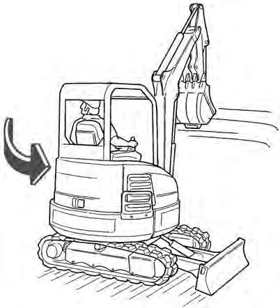
Figure 131
The joystick lock switch disengages the hydraulic control functions from the joysticks when the console is raised [Figure 131]
NOTE: If the engine stops, the boom / bucket (attachments) can be lowered to the ground using hydraulic pressure in the accumulator.
The control console must be in the locked down position, and the key switch in the ON position.
Use the control lever to lower the boom. Lower the control console to engage the hydraulic control functions of the joysticks [Figure 131]
OPERATING PROCEDURE (CONT’D)
Lifting Objects
Do not exceed the Rated Lift Capacity.
Warning
AVOID INJURY OR DEATH
Do not exceed rated lift capacity. Excessive load can cause tipping or loss of control.
W-2374-0500
NOTE:Load Holding Valves may be required for lifting objects. Check the regulation in your area. See your Bobcat dealer for load holding valves for your model excavator.
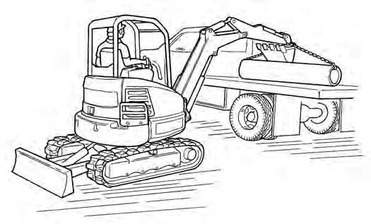
Extend the bucket cylinder completely and lower the boom to the ground. Stop the engine.
Wrap the chain assembly around the bucket mounting plate.
NA1424
Make sure the load is evenly weighted and centred on the lifting chain, and is secured to prevent the load from shifting [Figure 132].
Lift and position the load. Once the load is in position and tension is removed from the lift chain (secondary lift system), remove the secondary lift system.
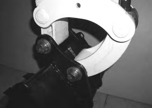
OPERATING PROCEDURE (CONT’D) Using The Clamp
Figure 133
The optional lifting clamp attachment (if equipped) gives the excavator a wider range of use and mobility for debris removal [Figure 133]
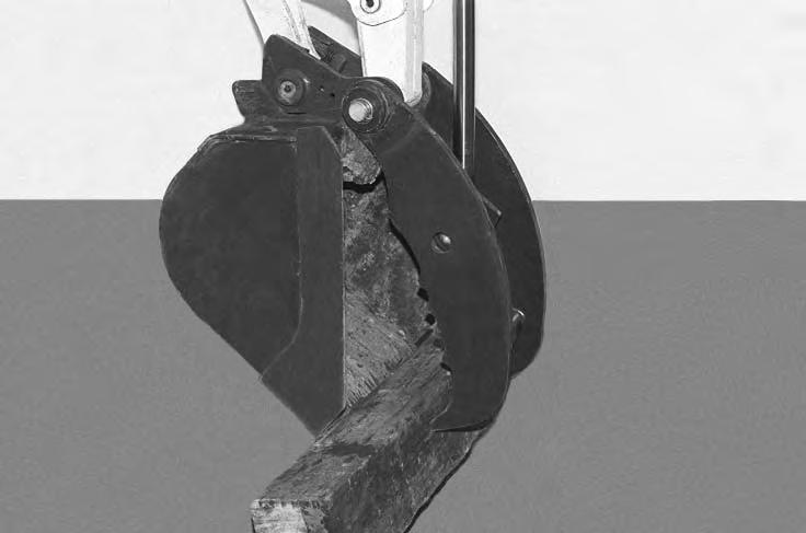
The lifting clamp cylinder must be fully retracted when the machine is being used for excavating.
The lift capacities are reduced by 122 kg (270 lb) if the excavator is equipped with the optional lifting clamp.
NOTE:Use care when operating the bucket and clamp functions on machines equipped with an X-Change and without a bucket or attachment installed. Cylinder damage can occur due to contact between the X-Change and the clamp when both cylinders are fully extended.
When Using Primary Auxiliary Hydraulics To Activate Clamp
Engage the auxiliary hydraulics and toggle to the Aux2 setting. (See Auxiliary Hydraulics on Page 51.)
Figure 134
LEFT HAND CONTROL LEVER (JOYSTICK)
RIGHT HAND CONTROL LEVER (JOYSTICK)
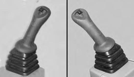
PRIMARY AUXILIARY HYDRAULICS
Move the switch (Item 1) [Figure 134] on the right control lever to the right to open the clamp. Move the switch to the left to close the clamp.
When Using Secondary Auxiliary Hydraulics To Activate Clamp
Move the switch (Item 2) [Figure 134] on the left control lever to the left open the clamp. Move the switch to the right to close the clamp.
OPERATING PROCEDURE (CONT’D)
Excavating
Lower the blade to increase digging performance.
Figure 135
Extend the arm, lower the boom, and open the bucket [Figure 135]
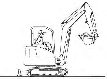
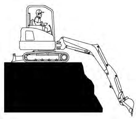
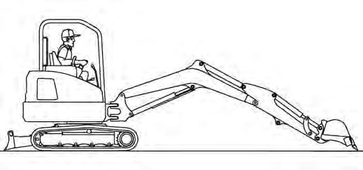
Figure 136
Retract the arm, while lowering boom and curling the bucket [Figure 136]
Raise the boom, retract the arm and curl the bucket [Figure 137]
Rotate the upperstructure.
NOTE:Do not allow the bucket teeth to contact the ground when swinging the upperstructure.
Warning
Keep all bystanders 6 m (20 ft) away from equipment when operating. Contact with moving parts, a trench cave-in or flying objects can cause injury or death.
W-2119-0910
Warning
AVOID INJURY OR DEATH
Check area to be excavated for overhead or underground electrical power lines. Keep a safe distance from electrical power lines.
W-2757-EN-0513
OPERATING PROCEDURE (CONT’D)
Excavating (Cont’d)
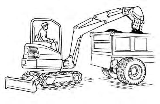
Look in the direction of rotation and make sure there are no bystanders in the work area before rotating the upperstructure [Figure 138]
Do not dig under the excavator [Figure 140]
Do not use the bucket as a breaker or pile driver. It is better to excavate hard or rocky ground after breaking it with other equipment. This will reduce damage to the excavator.
Do not move the excavator while the bucket is in the ground.
Dig only by moving the boom and arm toward the excavator.
Do not back dig (digging by moving the boom and arm away from the excavator). Damage to the X-Change and attachments may occur.
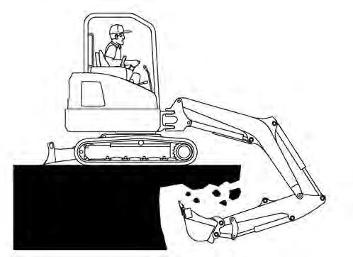
[Figure 139]
Avoid operating hydraulics over relief pressure. Failure to do so will overheat hydraulic components. I-2220-0503