18 minute read
AND CONSOLES (CONT’D)


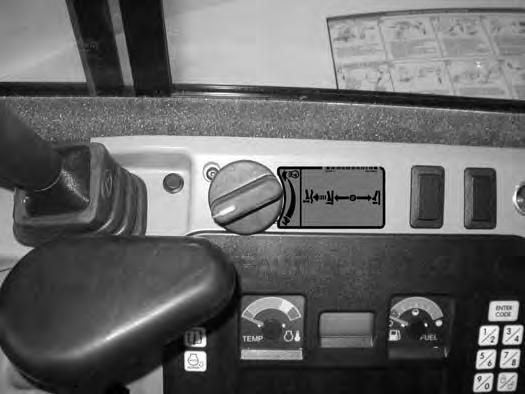
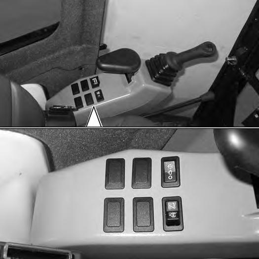
The auto idle feature (when engaged) will reduce the engine speed to low idle when the control levers (joystick, blade, travel, etc.) are in NEUTRAL and not used for approximately four seconds. The engine rpm will return to the set position as soon as any control lever is activated.
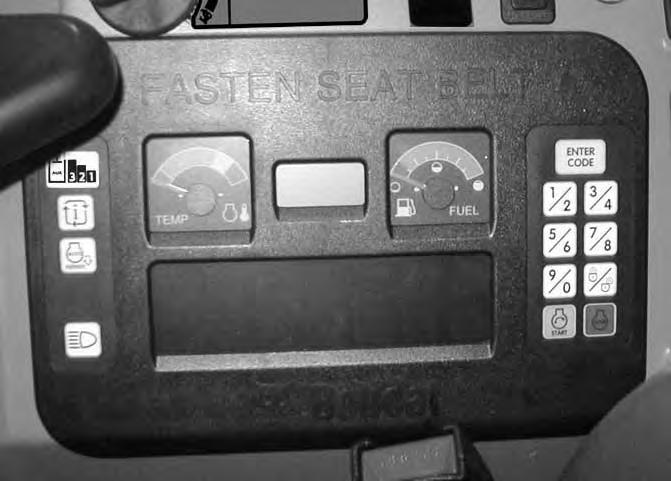
The automatic idle switch (Item 1) [Figure 14] is used to engage or disengage the automatic idle feature.
Press the switch (Item 1) once to engage automatic idle and the icon (Item 2) will illuminate. Press the switch (Item 1) a second time to disengage automatic idle, the icon (Item 2) [Figure 14] will be OFF.
NOTE:Always disengage the auto idle feature when loading or unloading the excavator onto a transport vehicle.
OPERATOR CANOPY (ROPS / TOPS) (IF EQUIPPED)
Description
The Bobcat excavator has available an operator canopy (ROPS / TOPS) as standard equipment to protect the operator if the excavator is tipped over. The seat belt must be worn for ROPS / TOPS protection.
Check the ROPS / TOPS canopy, mounting, and hardware for damage. Never modify the ROPS / TOPS canopy. Replace the canopy and hardware if damaged. See your Bobcat dealer for parts.
ROPS / TOPS - Roll-Over Protective Structure per ISO 12117-2, and Tip-Over Protective Structure per ISO 12117.
Warning
Never modify operator cab by welding, grinding, drilling holes or adding attachments unless instructed to do so by Bobcat Company. Changes to the cab can cause loss of operator protection from rollover and falling objects, and result in injury or death.
W-2069-0200
OPERATOR CAB (ROPS / TOPS)
Description
The Bobcat excavator has an operator cab (ROPS / TOPS) as standard equipment to protect the operator if the excavator is tipped over. The seat belt must be worn for ROPS / TOPS protection.
Check the ROPS / TOPS cab, mounting, and hardware for damage. Never modify the ROPS / TOPS cab. Replace the cab and hardware if damaged. See your Bobcat dealer for parts.
ROPS / TOPS - Roll-Over Protective Structure per ISO 12117-2, and Tip-Over Protective Structure per ISO 12117.
Warning
Never modify operator cab by welding, grinding, drilling holes or adding attachments unless instructed to do so by Bobcat Company. Changes to the cab can cause loss of operator protection from rollover and falling objects, and result in injury or death.
W-2069-0200
OPERATOR CAB (ROPS / TOPS) (CONT’D)
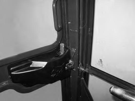
Cab Door

15
OPERATOR CAB (ROPS / TOPS) (CONT’D)

Front Window
Opening The Front Window (Early Models)
Figure 19
Press the top window latch (Item 1) [Figure 19] (both sides).
When the window is fully raised, the latch (Item 1) [Figure 21] (both sides) will close on the bracket in the latched position.

Pull down slightly on the window to make sure it is fully latched.
Closing The Front Window (Early Models)
Support the window while releasing the window latch (Item 1) [Figure 21] (both sides).
Use both window grab handles (Item 1) [Figure 20] to pull the window down fully.
Press the top of the window in until the latch (Item 1) [Figure 19] locks into the latched position (both sides).
Pull inward slightly on the window to make sure it is fully latched in the closed position.
Use both window grab handles (Item 1) [Figure 20] to pull the top of the window in.
Continue moving the window in and up over the operator’s head until the window is fully raised.
OPERATOR CAB (ROPS / TOPS) (CONT’D)
Front Window (Cont’d)
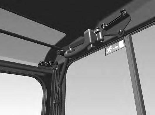
Opening The Front Window (Later Models)
Press the window latch button (Item 1) [Figure 22] (both sides).
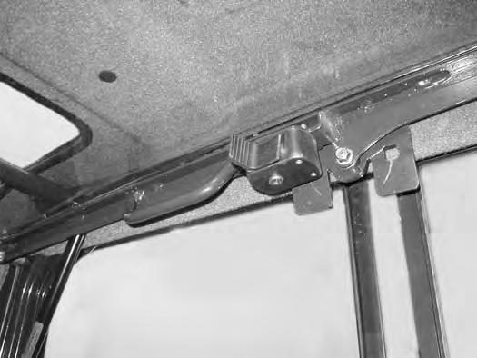
When the window is fully raised, the latch (Item 1) [Figure 24] (both sides) will close on the bracket in the latched position.
Pull down and forward slightly on the window to make sure it is fully latched.
Closing The Front Window (Later Models)
Use both window grab handles to support the window while pressing the window latch button (Item 2) [Figure 24] (both sides).
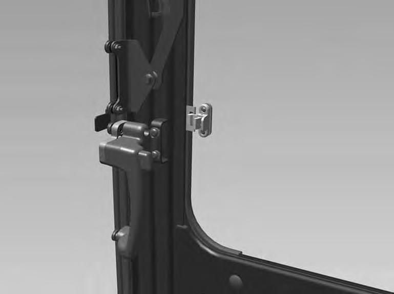
Use both window grab handles (Item 1) [Figure 23] to pull the window down fully.
Press the top of the window in until the latch locks into the latched position (both sides) [Figure 22].
Pull inwards and upward slightly on the window to make sure it is fully latched in the closed position.
Use both window grab handles (Item 1) [Figure 23] to pull the top of the window in.
Continue moving the window in and up over the operator’s head until the window is fully raised.
OPERATOR CAB (ROPS / TOPS) (CONT’D)

Front Wiper
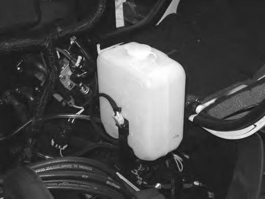
Window Washer Reservoir
OPERATOR CAB (ROPS / TOPS) (CONT’D)
Right Side Windows
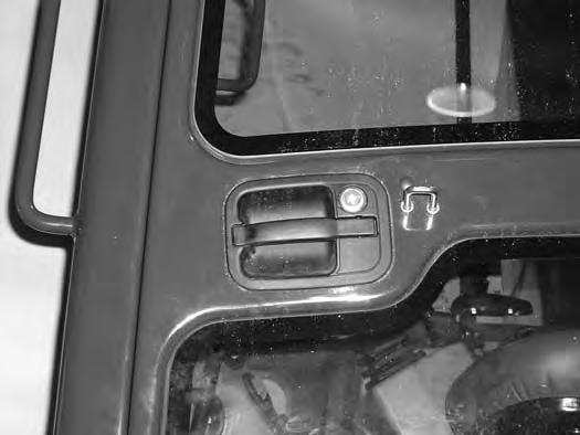
Opening The Right Rear Window

Figure 27
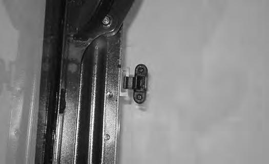
Raise the latch (Item 1) [Figure 27] located at the rear of the front window.
Figure 28
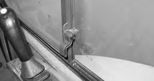
Pull out on the latch (Item 1) [Figure 28]
Figure 29
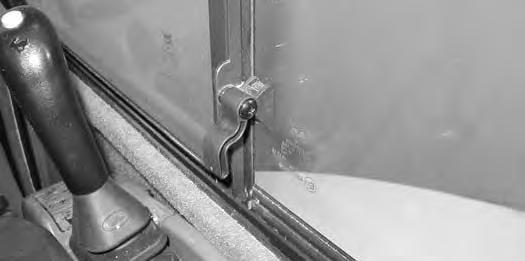
Pull the latch (Item 1) [Figure 29] forward to open the window. When the window is in the open position, push down on the latch (Item 1) [Figure 27]

Closing The Right Rear Window
Raise the latch (Item 1) [Figure 27].
Push the latch (Item 1) [Figure 29] back to close the window. Rotate the latch (Item 1) [Figure 27] down.

Opening The Right Front Window
Figure 30
Raise the latch (Item 1) [Figure 30] located at the rear of the front window.
Figure 31
Pull back on the latch (Item 1) [Figure 31]
32
Pull the latch (Item 1) [Figure 32] back to open the window.
When the window is in the open position, push down on the latch (Item 1) [Figure 30]
Closing The Right Front Window
Raise the latch (Item 1) [Figure 30]
Push the handle (Item 1) [Figure 32] forward to close the window. Rotate the latch (Item 1) [Figure 30] down.
OPERATOR CAB (ROPS / TOPS) (CONT’D)

Heating, Ventilation, And Air Conditioning Ducting
The HVAC louvers (Item 1) [Figure 33] can be positioned as needed to direct the air flow to various areas in the cab
Operating Tip: To increase heating or cooling efficiency, move the Recirculation / Fresh Air Control knob (Item 2) [Figure 33] to the recirculation position. This will allow the air to recirculate through the HVAC system and improve temperature control. If left in the fresh air position, the HVAC system will also need to heat or cool the ambient air that is drawn in from the outside, slowing and / or reducing the temperature change inside the cab.
Emergency Exit
The door, the right side rear window and the front window provide exits.
Right Side Rear Window
Figure 34
Front Window
Figure 35
Exit through the window [Figure 34]
Open the front window and exit [Figure 35]
NOTE:If the excavator has a Special Applications Kit installed, the front window is NOT an emergency exit.

This excavator may be equipped with a motion alarm system. The motion alarm (Item 1) [Figure 36] is located inside the rear of the excavator.

This machine is equipped with a motion alarm. ALARM MUST SOUND! when operating forward or backward.
Failure to maintain a clear view in the direction of travel could result in serious injury or death.
The operator is responsible for the safe operation of this machine.
The motion alarm will sound when the operator moves the travel control levers (Item 1) [Figure 38] in either the forward or reverse direction.
If alarm does not sound or for adjustment instructions, see inspection and maintenance instructions for the motion alarm system in the preventive maintenance section of this manual. (See MOTION ALARM SYSTEM on Page 113.)
The motion alarm can be temporarily disabled by pressing the motion alarm switch (Item 1) [Figure 37] while the machine is moving. As soon as the travel levers are returned to the NEUTRAL position, the motion alarm will be enabled.
Travel Controls
Forward And Reverse Travel
NOTE: The following procedures describe forward, reverse, left and right as seated in the operator’s seat.
Figure 39
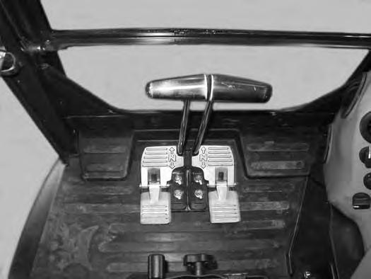
Put the blade so that it is at the front of the machine (as you sit in the operator’s seat). Slowly move both steering levers* (Item 1) [Figure 38] forward for forward travel; backward for reverse travel.
* Travel can also be controlled with foot pedals (Item 2) [Figure 38]. Pivot the heel of the pedals forward for additional space on the floor.
Warning
AVOID INJURY OR DEATH
•Check the blade location before travelling. When the blade is to the rear, operate the steering levers / foot pedals in the opposite direction to when the blade is in the front.
•Move the steering levers / foot pedals slowly. Abrupt lever motion will cause the machine to jerk.
W-2235-EN-1009
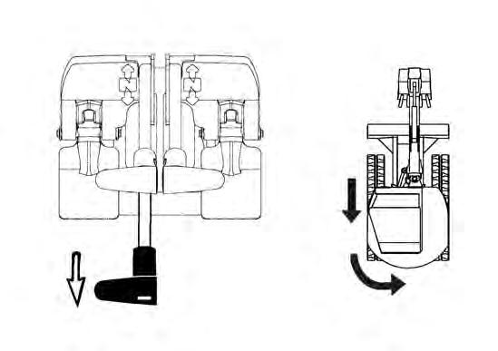
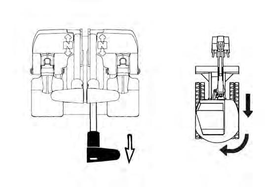
Push the left steering lever forward to turn right [Figure 39] while travelling forward.
Figure 40
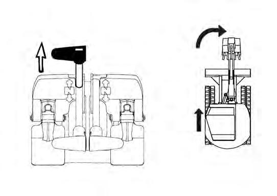
Pull the left steering lever backward to turn right while travelling backward [Figure 40]
TRAVEL CONTROLS (CONT’D)
Turning (Cont’d)
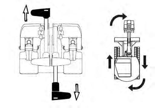
Counter-Rotation Right Turn
41
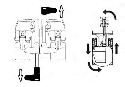
Push the left steering lever forward and pull the right steering lever backward [Figure 41] Left Turn
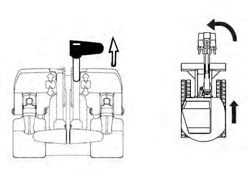
Pull the right steering lever backward to turn left while travelling backward [Figure 43]
Counter-Rotation Left Turn
44
Push the right steering lever forward to turn left while travelling forward [Figure 42]
Push the right steering lever forward and pull the left steering lever backward [Figure 44]
HYDRAULIC CONTROLS Description
The work equipment (boom, arm, bucket, and upperstructure slew) is operated by using the left and right control levers (joysticks).
Left Control Lever (Joystick)
Figure 45
The left lever (joystick) is used to operate the arm and slew the upperstructure [Figure 45]
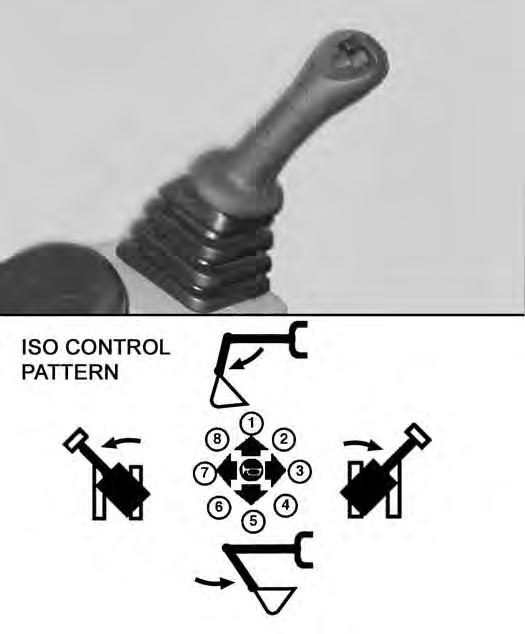
1. Arm out.
2. Arm out and slew right.
3. Slew right.
4. Arm in and slew right.
5. Arm in.
6. Arm in and slew left.
7. Slew left.
8. Arm out and slew left.
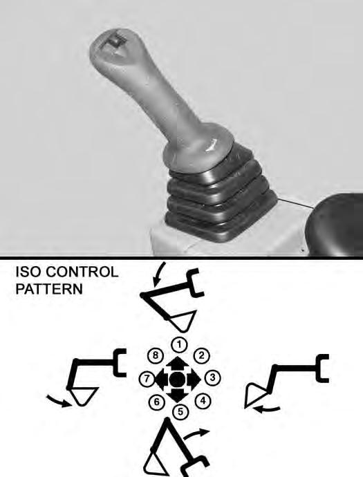
Right Control Lever (Joystick)
Figure 46
The right lever (joystick) is used to operate the boom and bucket [Figure 46].
1. Boom lower.
2. Boom lower and bucket dump.
3. Bucket dump.
4. Boom raise and bucket dump.
5. Boom raise.
6. Boom raise and bucket curl.
7. Bucket curl.
8. Boom lower and bucket curl.
Warning
AVOID INJURY OR DEATH
Before leaving the machine:
•Lower the work equipment to the ground.
•Lower the blade to the ground.
•Stop the engine and remove the key.
•Raise the control console.
W-2780-0109
HYDRAULIC CONTROLS (CONT’D)
Quick Couplers
Warning
AVOID BURNS
Hydraulic fluid, tubes, fittings and quick couplers can get hot when running machine and attachments. Be careful when connecting and disconnecting quick couplers.
W-2220-0396
Warning
AVOID INJURY OR DEATH
Diesel fuel or hydraulic fluid under pressure can penetrate skin or eyes, causing serious injury or death. Fluid leaks under pressure may not be visible. Use a piece of cardboard or wood to find leaks. Do not use your bare hand. Wear safety goggles. If fluid enters skin or eyes, get immediate medical attention from a doctor familiar with this injury.
W-2072-EN-0909
47
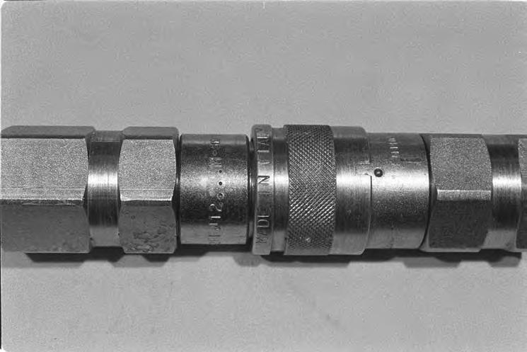
Excavators and attachments are supplied with flush faced couplers (Item 1) [Figure 47].
To Connect:
Remove any dirt or debris from the surface of both the male and female couplers, and from the outside diameter of the male coupler. Visually check the couplers for corroding, cracking, damage, or excessive wear, if any of these conditions exist, the coupler(s) (Item 1) [Figure 47] must be replaced.
Install the male coupler into the female coupler. Full connection is made when the ball release sleeve slides forward on the female coupler.
To Disconnect:
Figure 48
Hold the male coupler (Item 1). Retract the sleeve (Item 2) [Figure 48] on the female coupler until the couplers disconnect.
HYDRAULIC CONTROLS (CONT’D)
Auxiliary Hydraulics
The primary auxiliary hydraulics has Selectable Auxiliary Hydraulic Flow. This allows the operator to select a hydraulic flow that matches the attachment hydraulic requirements. The auxiliary hydraulics can be set to Aux3, Aux2, Aux1 or off. Aux3 allows maximum hydraulic flow, Aux2 allows medium hydraulic flow and Aux1 allows low hydraulic flow.
Examples for setting Selectable Auxiliary Hydraulic Flow and the attachment used:
Press the Auxiliary Hydraulics button on the right console (Item 1) [Figure 49] (an audible beep will sound each time the auxiliary button is pressed).

The first time the Auxiliary Hydraulics button is pressed, the last selected auxiliary hydraulic flow (Aux3, Aux2 or Aux1) will appear in the data display (Item 2) [Figure 49] for approximately two seconds and then the data screen will revert back to the previous information on the data display.
To change the auxiliary flow, press the Auxiliary Hydraulics button (Item 1) to toggle through the settings, each time the button is pressed, the next setting will appear in the data display (Item 2) [Figure 49]. Once the desired setting is selected, it will stay at that setting until a different auxiliary flow is selected by the operator. (Example: If Aux2 has been selected, after key OFF and engine restart, the Aux2 setting will still be the active hydraulic flow when auxiliary hydraulics are activated.)
NOTE:Use only approved attachments for your model excavator. Attachments are approved for each model of excavator based on various factors. Using unapproved attachments could cause damage to the attachment or to the excavator.
Move the switch (Item 1) [Figure 50] on the right control lever to the right to supply hydraulic flow to the female coupler. Move the switch to the left to supply hydraulic flow to the male coupler. If you move the switch halfway, the auxiliary functions move at approximately one-half speed.
Press the switch (Item 2) [Figure 50] on the front of the handle to provide constant flow to the female coupler.
NOTE: Pressing the switch (Item 1) to the left while pressing the switch (Item 2) [Figure 50] on the front of the handle will provide constant flow to the male coupler.
Press the switch (Item 2) [Figure 50] a second time to stop auxiliary flow to the quick couplers.
NOTE:Reverse flow can cause damage to some attachments. Use reverse flow with your attachment only if approved. See your attachment Operation & Maintenance Manual for detailed information.
HYDRAULIC CONTROLS (CONT’D)
Relieve Hydraulic Pressure (Excavator And Attachment)
Excavator:
Put the attachment flat on the ground. Stop the engine and turn the key to ON (Standard) or press [ENTER CODE] Button (Keyless).
NOTE: The left console must be fully lowered for relieving hydraulic pressure.
Press [AUX HYD] Button (Item 1) [Figure 49] and then move the switch (Item 1) [Figure 50] to the right and left several times.
Attachments:
• Follow procedure above to release pressure in excavator.
•Connect male coupler from attachment to female coupler of excavator then repeat procedure above. This will release pressure in the attachment.
•Connect the female coupler from the attachment.
Hydraulic pressure in the auxiliary hydraulic system can make it difficult to engage quick couplers to an attachment.
HYDRAULIC CONTROLS (CONT’D)
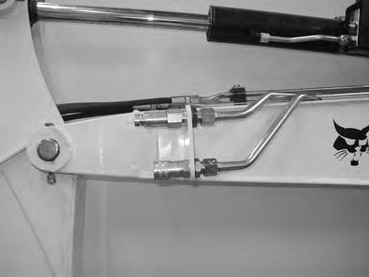
Secondary Auxiliary Hydraulics (If Equipped)
When equipped with secondary auxiliar y hydraulics, the second set of hydraulic couplers will be mounted on the right side of the arm.
Relieve Hydraulic Pressure (Excavator And Attachment)
Excavator:
Put the attachment flat on the ground.
Stop the engine and turn the key to ON (Standard) or press [ENTER CODE] Button (Keyless).

NOTE: The left console must be fully lowered for relieving hydraulic pressure.
Move the boom swing / secondary auxiliary hydraulic switch (Item 1) [Figure 51] to the right, secondary auxiliary hydraulic position.
Move the switch (Item 1) [Figure 52] to the right and left several times.
Attachments:
• Follow procedure above to release pressure in excavator.
•Connect male coupler from attachment to female coupler of excavator then repeat procedure above. This will release pressure in the attachment.
•Connect the female coupler from the attachment.
Hydraulic pressure in the auxiliar y hydraulic system can make it difficult to engage quick couplers to an attachment.
Move the switch (Item 1) [Figure 52] on the left control lever to the right to supply hydraulic flow to the female coupler. Move the switch to the left to supply hydraulic flow to the male coupler. If you move the switch halfway, the auxiliary functions move at approximately one-half speed.
HYDRAULIC CONTROLS (CONT’D)
Return To Tank Valve
The optional return to tank valve (if equipped) is located under the right side cover at the front of the control valve.
Figure 53
Rotate the lever (Item 1) [Figure 53] clockwise to direct auxiliary return hydraulic fluid to the reservoir.
Rotate the lever (Item 1) [Figure 53] anticlockwise for two way hydraulic auxiliary flow operation.
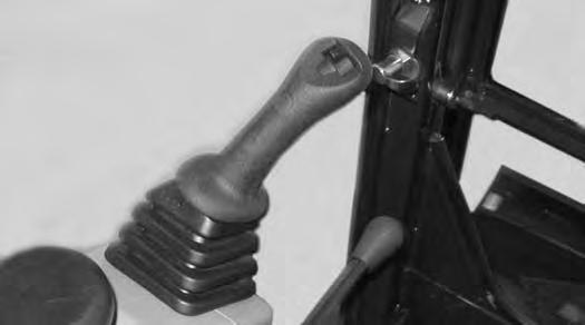
Blade Control Lever
Raising And Lowering Blade
Figure 54
Pull the lever backward to raise the blade (Item 1) [Figure 54]
Push the lever forward to lower the blade (Item 2) [Figure 54]
Push the lever forward until the lever is in the locked position (Item 3) [Figure 54] to put the blade in the float position.
Pull the lever backward to unlock from the float position.
NOTE: Keep blade lowered for increased digging performance.
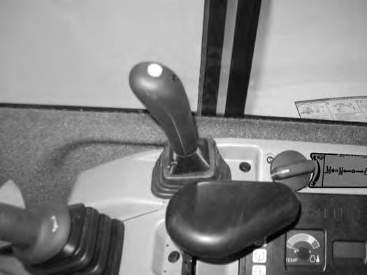
Engine Speed Control Dial
Setting Engine Speed (RPM)
Figure 55
The engine speed control dial (Item 1) [Figure 55] controls engine rpm.
Rotate the engine speed control dial anticlockwise (Item 2) to reduce engine rpm. Rotate the engine speed control dial clockwise (Item 3) [Figure 55] to increase engine rpm.
The switch (Item 1) [Figure 56] on the left control lever (joystick) controls boom swing. Move the switch to the left to swing the boom to the left. Move the switch to the right to swing the boom to the right.
If Equipped With Secondary Auxiliary Hydraulics:
If the machine is equipped with secondar y auxiliary hydraulic couplers, the switch (Item 2) [Figure 56] is used to select either the boom swing function or the secondar y auxiliary hydraulic function.
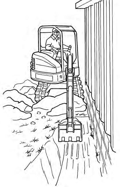
Move the switch (Item 2) [Figure 56] to the left to select boom swing function, move the switch to the right to select secondary auxiliary hydraulic function.
NOTE: The purpose of the boom swing is to offset the boom with respect to the upperstructure for digging close to a structure [Figure 57].
BOOM LOAD HOLDING VALVE
Description
The boom load holding valve (if equipped) will hold the boom in it’s current position in the event of hydraulic pressure loss.
NOTE:Load Holding Valves may be required for lifting objects. Check the regulation in your area. See your Bobcat dealer for load holding valves for your model excavator.
Warning
AVOID INJURY OR DEATH
Do Not work or stand under raised work equipment or attachment.
W-2793-0409
Lowering Boom With Load Holding Valve
NOTE:The boom load holding valve is required for object handling applications.
Warning
AVOID BURNS
Hydraulic fluid, tubes, fittings and quick couplers can get hot when running machine and attachments. Be careful when connecting and disconnecting quick couplers.
W-2220-0396
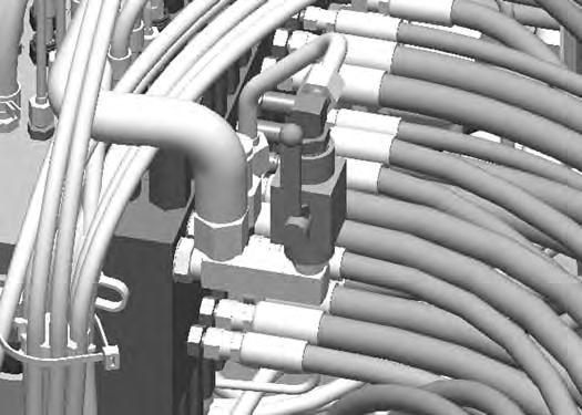
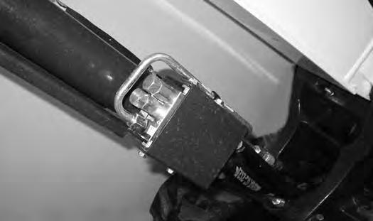
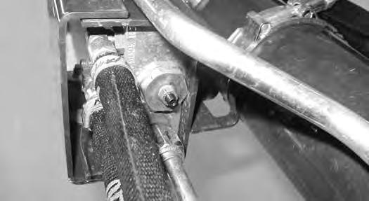
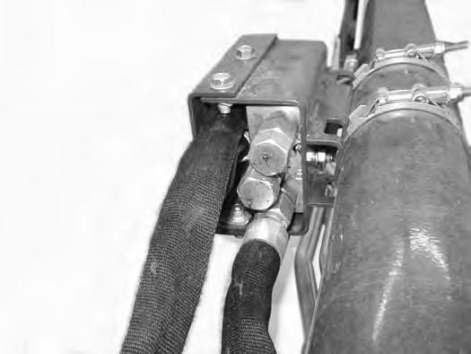
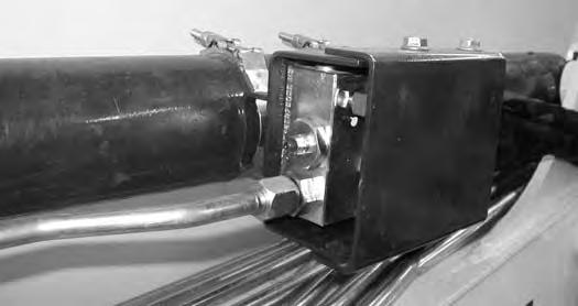
If the excavator is equipped with a boom load holding valve (Item 1) [Figure 58], it will be attached to the boom cylinder at the base end.
NOTE:DO NOT remove or adjust the two port relief valves (Item 2) [Figure 58]. If the port relief valves have been tampered with, see your Bobcat dealer for service.
BOOM LOAD HOLDING VALVE (CONT’D)
Lowering Boom With Load Holding Valve (Cont’d)
Figure 60
Lowering procedures:
With base end hose failure:
Loosen the jam nut (Item 1). Install a hex wrench into the valve screw (Item 2) [Figure 60] and slowly rotate the screw clockwise 1/8 to 1/4 turn and allow the boom to lower to the ground.
After the boom is fully lowered, rotate the screw anticlockwise (Item 2) 1/8 to 1/4 turn and tighten the lock nut (Item 1) [Figure 60]
With rod end hose failure - with accumulator pressure:
Place a container under the valve and hose end to contain hydraulic fluid. Enter the excavator and turn the key to the ON position but do not start the engine. Slowly move the joystick boom lower function and allow the boom to lower to the ground.
With rod end hose failure and NO accumulator pressure:
Remove the boom base end hose from the boom load holding valve. Place a container under the valve and base end hose to contain hydraulic fluid.
Loosen the jam nut (Item 1). Install a hex wrench into the valve screw (Item 2) [Figure 60] and slowly rotate the screw clockwise 1/8 to 1/4 turn and allow the boom to lower to the ground.
After the boom is fully lowered, rotate the screw (Item 2) anticlockwise 1/8 to 1/4 turn and tighten the lock nut (Item 1) [Figure 60]. Reinstall the base end hose.
Loss of hydraulic pressure:
Use the same procedure as: With rod end hose failure and NO accumulator pressure.
ARM LOAD HOLDING VALVE
Description
The arm load holding valve (if equipped) will hold the arm in it’s current position in the event of hydraulic pressure loss.
NOTE:Load Holding Valves may be required for lifting objects. Check the regulation in your area. See your Bobcat dealer for load holding valves for your model excavator.
Warning
AVOID INJURY OR DEATH
Do Not work or stand under raised work equipment or attachment.
W-2793-0409
Lowering Arm With Load Holding Valve
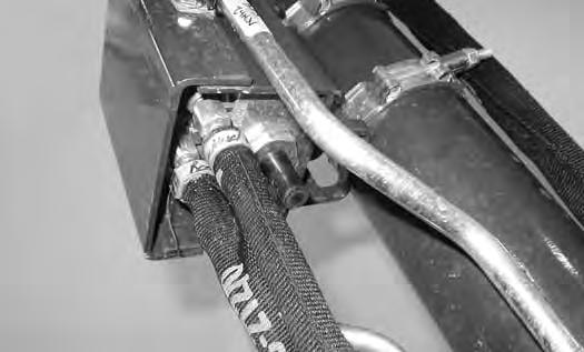
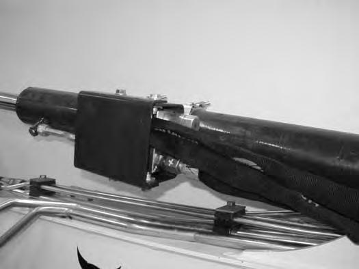
NOTE: DO NOT remove or adjust the two port relief valves (Item 1) [Figure 62]. If the port relief valves have been tampered with, see your Bobcat dealer for service.
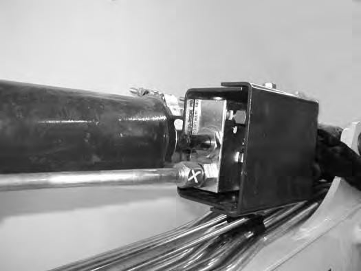
If the excavator is equipped with arm load holding valve (Item 1) [Figure 61], it will be attached to the arm cylinder base end as shown.
Warning
AVOID BURNS
Hydraulic fluid, tubes, fittings and quick couplers can get hot when running machine and attachments. Be careful when connecting and disconnecting quick couplers.
ARM LOAD HOLDING VALVE (CONT’D)
Lowering Arm With Load Holding Valve (Cont’d)
Figure 64
Lowering procedures:
With base end hose failure:
Loosen the jam nut (Item 1). Install a hex wrench into the valve screw (Item 2) [Figure 64] and slowly rotate the screw clockwise 1/8 to 1/4 turn and allow the arm to lower.
After the arm is lowered, rotate the screw anticlockwise (Item 2) the same 1/8 to 1/4 turn and tighten the lock nut (Item 1) [Figure 64]
With rod end hose failure - with accumulator pressure:
Place a container under the valve and hose end to contain hydraulic fluid. Enter the excavator and turn the key to the ON position but do not start the engine. Move the joystick arm retract function to slowly lower the arm.
With rod end hose failure and NO accumulator pressure:
Remove the arm base end hose from the arm load holding valve. Place a container under the valve and base end hose to contain hydraulic fluid.
Loosen the jam nut (Item 1). Install a hex wrench into the valve screw (Item 2) [Figure 64] and slowly rotate the screw clockwise 1/8 to 1/4 turn and allow the arm to lower.
After the arm is lowered, rotate the screw (Item 2) anticlockwise 1/8 to 1/4 turn and tighten the lock nut (Item 1) [Figure 64]. Reinstall the base end hose.
Loss of hydraulic pressure:
Use the same procedure as: With rod end hose failurewith NO accumulator pressure above.
Daily Inspection
Daily Inspection And Maintenance
Figure 65
Warning
Operator must have instructions before operating the machine. Untrained operators can cause injury or death.
W-2001-0502
Fluids such as engine oil, hydraulic fluid, coolants, etc. must be disposed of in an environmentally safe manner. Some regulations require that certain spills and leaks on the ground must be cleaned in a specific manner. See local bylaws for correct disposal.
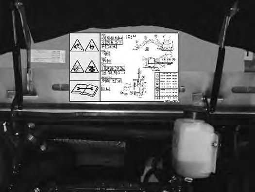
Maintenance work must be done at regular intervals. Failure to do so will result in excessive wear and early failures. The Service Schedule is a guide for correct maintenance of the Bobcat Excavator. The decal (Item 1) [Figure 65] is located inside the rear door. (See SERVICE SCHEDULE on Page 109.)
Check the following items before each day of operation:
•Operator Canopy or Cab (ROPS / TOPS) and mounting hardware.
•Seat belt and mounting hardware. Replace seat belt if damaged.
•Check for damaged decals, replace as needed.
•Check control console lockout.
•Check attachment coupler system (if equipped) for damage or loose parts.
•Air cleaner and intake hoses / clamps.
•Engine oil level and engine for leaks.
•Engine coolant level and engine for leaks.
•Check engine area for flammable materials.
•Check hydraulic fluid level and system for leaks.
•Check indicator lights for correct operation.
•Grease all pivot points.
•Check cylinder and attachment pivot points.
•Check the track tension.
•Repair broken and loose parts.
•Clean cab heater filter (if equipped).
•Check front horn and motion alarm (if equipped) for proper function.
Important
Pressure Washing Decals
•Never direct the stream at a low angle toward the decal that could damage the decal causing it to peel from the surface.
•Direct the stream at a 90 degree angle and at least 300 mm (12 in) from the decal. Wash from the centre of the decal toward the edges.
I-2226-EN-0910
Important
This machine is factory equipped with a spark arrester exhaust system.
The spark arrester muffler, if equipped, must be cleaned to keep it in working condition. The spark arrester muffler must be serviced by dumping the spark chamber every 100 hours of operation.
On some models, the turbocharger functions as the spark arrester and must operate correctly for proper spark arrester function.
If this machine is operated on flammable forest, brush, or grass covered land, a spark arrester attached to the exhaust system may be required and must be maintained in working order. Refer to local laws and regulations for spark arrester requirements.
I-2284-EN-0909
PRE-STARTING PROCEDURE
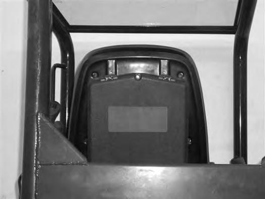
Operation & Maintenance Manual And Operator’s Handbook Locations
66
Entering The Excavator
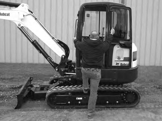
Warning
AVOID INJURY OR DEATH
Instructions are necessary before operating or servicing machine. Read and understand the Operation & Maintenance Manual, Operator’s Handbook and signs (decals) on machine. Follow warnings and instructions in the manuals when making repairs, adjustments or servicing. Check for correct function after adjustments, repairs or service. Untrained operators and failure to follow instructions can cause injury or death.
W-2003-0807
Read and understand the Operation & Maintenance Manual (Item 1) [Figure 66] (located inside the storage box on the back of the operator’s seat) and the Operator’s Handbook (Item 1) [Figure 67] before operating.