34 minute read
FUEL SYSTEM


Fuel Specifications
NOTE: Contact your local fuel supplier to receive recommendations for your region.
U.S. Standard (ASTM D975)
Use only clean, high quality diesel fuel, Grade Number 2-D or Grade Number 1-D.
Ultra low sulfur diesel fuel must be used in this machine. Ultra low sulfur is defined as 15 mg/kg (15 ppm) sulfur maximum.
The following is one suggested blending guideline that should prevent fuel gelling during cold temperatures:
Biodiesel Blend Fuel
Biodiesel blend fuel has unique qualities that should be considered before using in this machine:
•Cold weather conditions can lead to plugged fuel system components and hard starting.
•Biodiesel blend fuel is an excellent medium for microbial growth and contamination that can cause corrosion and plugging of fuel system components.
•Use of biodiesel blend fuel may result in premature failure of fuel system components, such as: plugged fuel filters and deteriorated fuel lines.
•Shorter maintenance intervals may be required, such as: cleaning the fuel system and replacing fuel filters and fuel lines.
•Using biodiesel blended fuels containing more than five percent biodiesel can affect engine life and cause deterioration of hoses, tubelines, injectors, injector pump, and seals.
NOTE:Biodiesel blend fuel may also be used in this machine. Biodiesel blend fuel must contain no more than five percent biodiesel mixed with ultra low sulfur petroleum based diesel. This biodiesel blend fuel is commonly marketed as B5 blended diesel fuel. B5 blended diesel fuel must meet ASTM specifications.
E.U. Standard (EN590)
Use only clean, high quality diesel fuel that meets the EN590 specifications listed below:
•Ultra low sulfur diesel fuel defined as 10 mg/kg (10 ppm) sulfur maximum.
•Diesel fuel with cetane number of 51.0 and above.
NOTE:Biodiesel blend fuel may also be used in this machine. Biodiesel blend fuel must contain no more than seven percent biodiesel mixed with ultra low sulfur petroleum based diesel. This biodiesel blend fuel is commonly marketed as B7 blended diesel fuel. B7 blended diesel fuel must meet EN590 specifications.
Apply the following guidelines if biodiesel blend fuel is used:
•Ensure the fuel tank is as full as possible at all times to prevent moisture from collecting in the fuel tank.
•Ensure that the fuel tank cap is securely tightened.
•Biodiesel blend fuel can damage painted surfaces, remove all spilled fuel from painted surfaces immediately.
•Drain all water from the fuel filter daily before operating the machine.
•Do not exceed engine oil change interval. Extended oil change intervals can cause engine damage.
•Before machine storage; drain the fuel tank, refill with 100% petroleum diesel fuel, add fuel stabilizer, and operate the engine for at least 30 minutes.
NOTE:Biodiesel blend fuel does not have long term stability and should not be stored for more than 3 months.
FUEL SYSTEM (CONT’D)
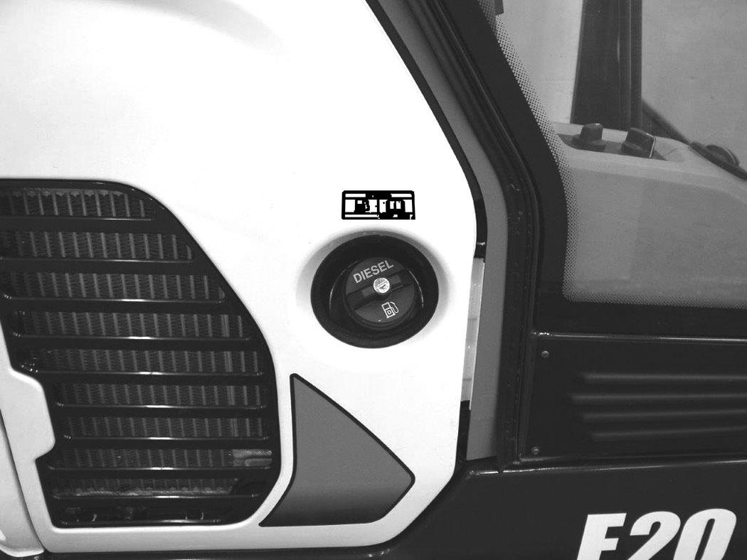
Filling The Fuel Tank
Figure 178
Warning
AVOID INJURY OR DEATH
Always clean up spilled fuel or oil. Keep heat, flames, sparks or lighted tobacco away from fuel and oil. Failure to use care around combustibles can cause explosion or fire.
W-2103-0508 P113441
The fuel cap uses the start key to unlock the fuel cap.
Remove the fuel fill cap (Item 1) [Figure 178]
Use a clean, approved safety container to add fuel. Add fuel only in an area that has a free movement of air and no flames or sparks. NO SMOKING!
Install and tighten the fuel fill cap.
Clean up any spilled fuel.
See the service schedule for the service interval when to remove water from or replace the fuel filter. (See SERVICE SCHEDULE on Page 101.)
NOTE:When filling the fuel tank, with the left console raised, turn the start switch to the ON position. As fuel is added to the tank, a buzzer will beep and the closer the tank gets to full, the quicker the beeps. When the tank is full, the buzzer will sound continuously. Stop fuelling when buzzer sounds continuously. Turn the start switch OFF.
Warning
AVOID INJURY OR DEATH
Stop and cool the engine before adding fuel. NO SMOKING! Failure to obey warnings can cause an explosion or fire.
W-2063-0807
FUEL SYSTEM (CONT’D)
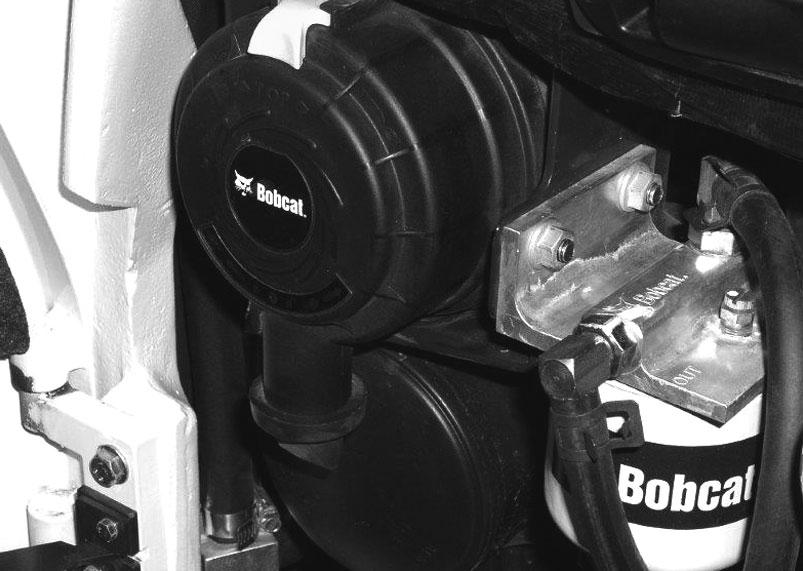
Fuel Filter
Removing Water
Open the tailgate. (See TAILGATE on Page 107.)
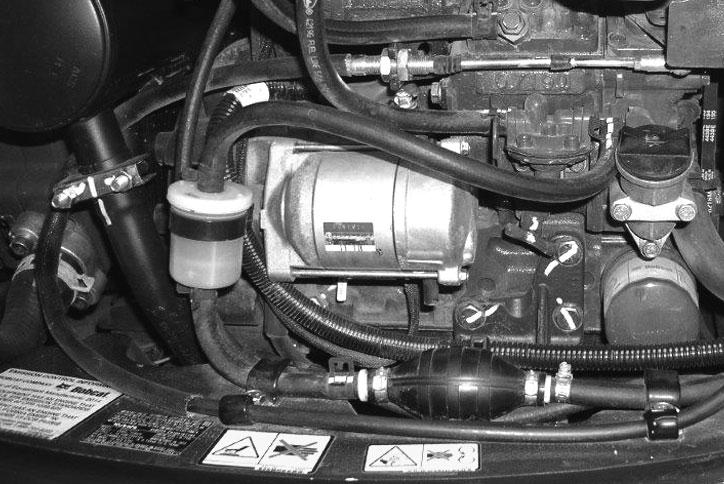
Figure 179
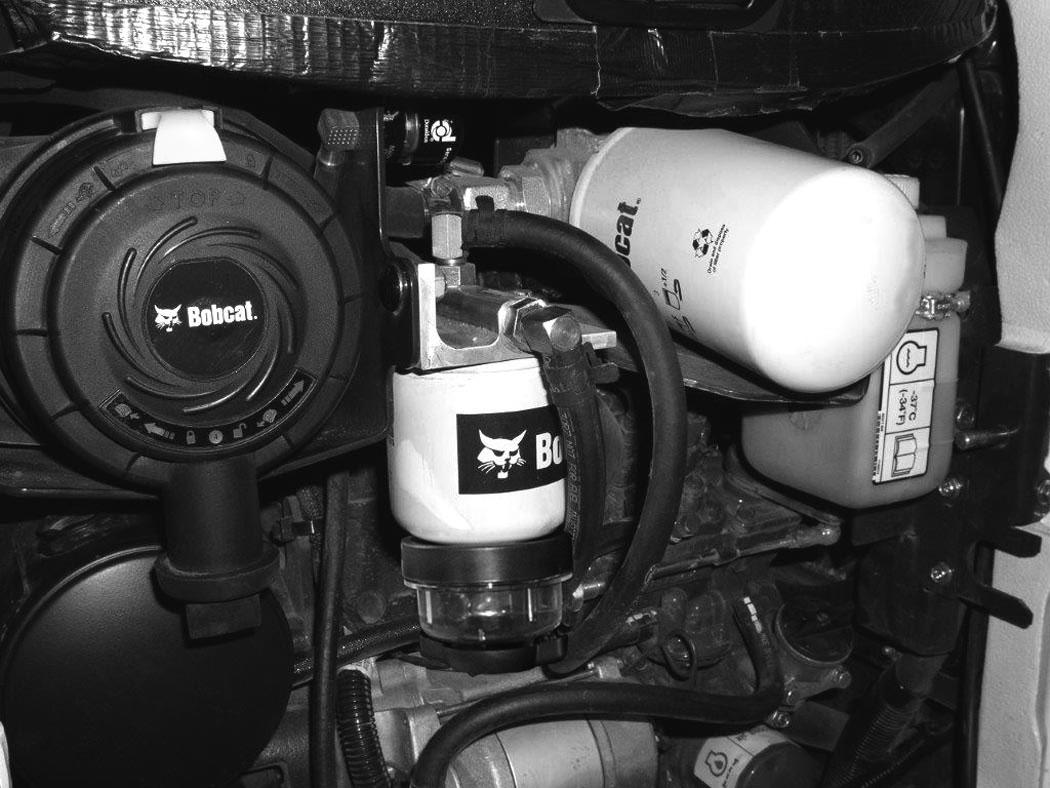
Loosen the drain (Item 1) [Figure 179] at the bottom of the filter to drain water from the filter into a container.
Inspect the fuel pre-filter (Item 3) [Figure 179] daily for moisture and contamination. Replace as necessary.
Clean up any spilled fuel.
Replacing Elements
Remove and replace the fuel pre-filter (Item 3) [Figure 179]
Remove the filter (Item 2) [Figure 179]
Clean the area around the filter housing. Put clean oil on the seal of the new filter. Install the fuel filter and hand tighten.
Remove the air from the fuel system. (See Removing Air From The Fuel System on Page 114.)
Warning
Avoid Injury Or Death
Diesel fuel or hydraulic fluid under pressure can penetrate skin or eyes, causing serious injury or death. Fluid leaks under pressure may not be visible. Use a piece of cardboard or wood to find leaks. Do not use your bare hand. Wear safety goggles. If fluid enters skin or eyes, get immediate medical attention from a doctor familiar with this injury.
W-2072-EN-0909
Draining The Fuel Tank
See the service schedule for the correct service interval. (See SERVICE SCHEDULE on Page 101.)
The fuel tank can be drained in several ways. See below.
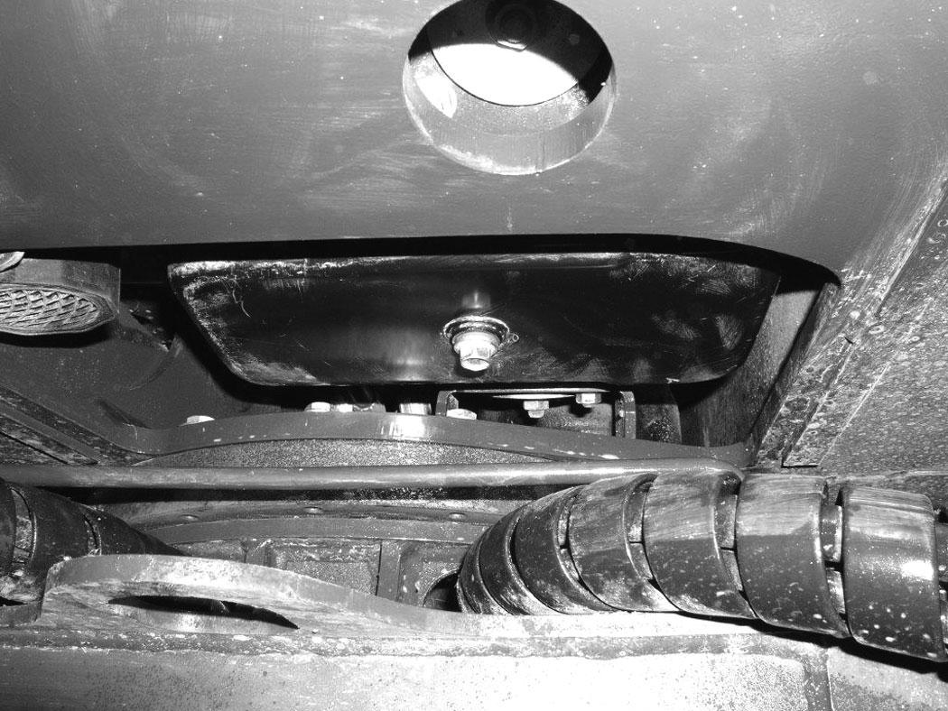
Figure 180
Rotate the upperstructure so the fuel tank drain plug (Item 1) is located between the rear tracks. Remove the drain plug (Item 1) [Figure 180]
Drain the fuel into the container.
Reuse, recycle or dispose of fuel in an environmentally safe manner.
Reinstall the drain plug.
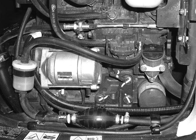
Figure 181
Second option for draining tank. Remove the fuel hose (Item 1) at the fuel pump. Route the hose out of the engine compartment and into a container. Squeeze the primer bulb (Item 2) [Figure 181] to start a siphon and drain the tank.

Reinstall the fuel hose (Item 1) [Figure 181]
FUEL SYSTEM (CONT’D)
Removing Air From The Fuel System
After replacing the fuel filter or when the fuel tank has run out of fuel, air must be removed from the fuel system before starting the engine.
Open the tailgate. (See Opening And Closing on Page 107.)
Warning
Avoid Injury Or Death
Diesel fuel or hydraulic fluid under pressure can penetrate skin or eyes, causing serious injury or death. Fluid leaks under pressure may not be visible. Use a piece of cardboard or wood to find leaks. Do not use your bare hand. Wear safety goggles. If fluid enters skin or eyes, get immediate medical attention from a doctor familiar with this injury.
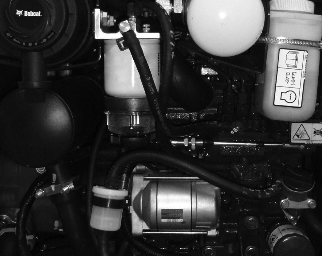
Open the fuel filter vent (Item 1) [Figure 182] and operate the hand pump (priming bulb) (Item 1) [Figure 183] until the fuel flows from the vent (Item 1) [Figure 182] with no air bubbles.
Close the vent (Item 1) [Figure 182]
Start the engine. It may be necessary to open the vent (Item 2) [Figure 183] (at the fuel injection pump) briefly until the engine runs smoothly.
ENGINE LUBRICATION SYSTEM Checking And Adding Engine Oil
Check the engine oil after every 8 - 10 hours of operation and before starting the engine. (See SERVICE SCHEDULE on Page 101.)
Figure 184
Open the tailgate and remove the dipstick (Item 1) [Figure 184].
Keep the oil level between the marks on the dipstick.
Use a good quality motor oil that meets the correct API Service Classification.
Engine Oil Chart
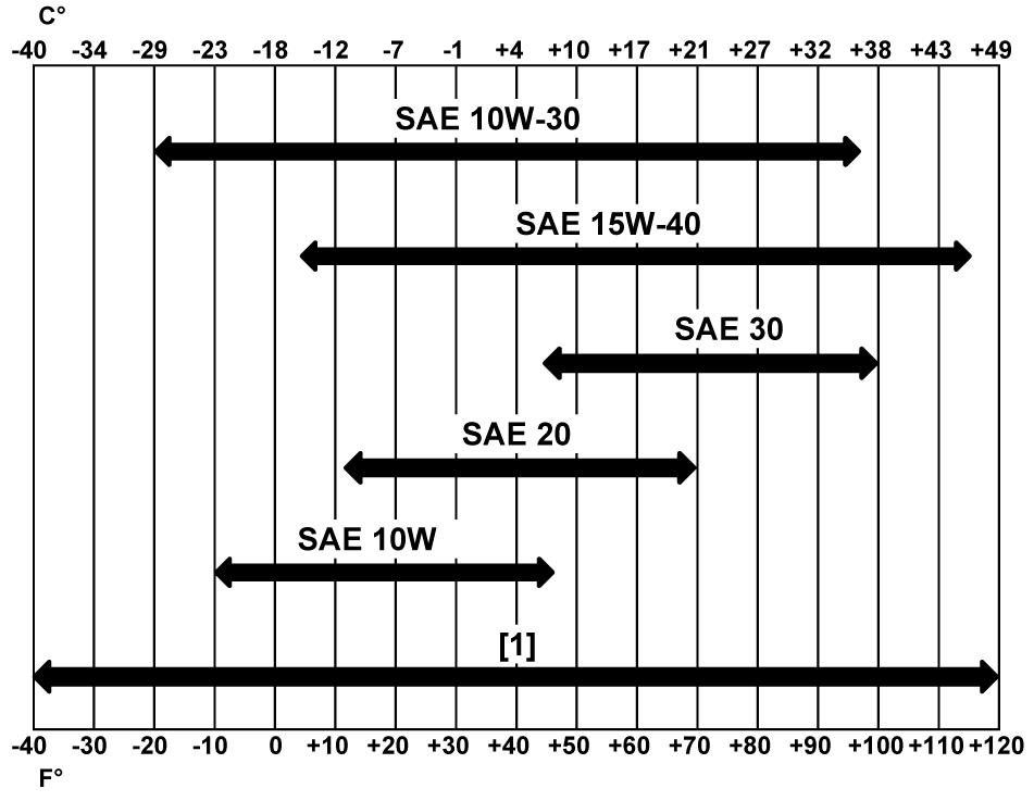
Figure 185
ENGINE OIL RECOMMENDED SAE VISCOSITY NUMBER (LUBRICATION OILS FOR DIESEL ENGINE CRANKCASE)
TEMPERATURE RANGE ANTICIPATED BEFORE NEXT OIL CHANGE (DIESEL ENGINES MUST USE API CLASSIFICATION CI-4 OR BETTER)
[1] Synthetic Oil - Use recommendation from Synthetic Oil Manufacturer.
Use good quality engine oil that meets API Service Classification of CI-4 or better [Figure 185].
Warning
Avoid Injury Or Death
Always clean up spilled fuel or oil. Keep heat, flames, sparks or lighted tobacco away from fuel and oil. Failure to use care around combustibles can cause explosion or fire.
W-2103-0508
ENGINE LUBRICATION SYSTEM (CONT’D)
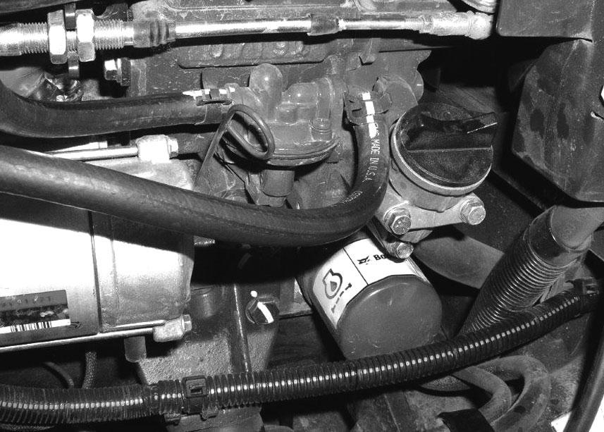
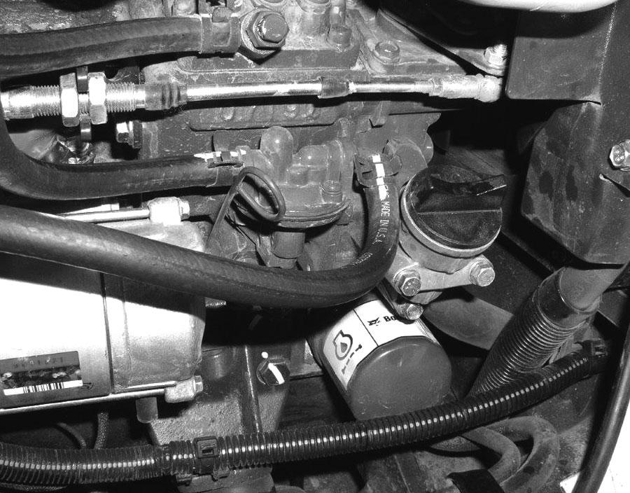
Removing And Replacing Oil And Filter
See the service schedule for the service interval for replacing the engine oil and filter. (See SERVICE SCHEDULE on Page 101.)
Rotate upperstructure so that the oil drain plug is between the rear tracks.
Run the engine until it is at operating temperature. Stop the engine.
Open the tailgate. (See Opening And Closing on Page 107.)
Place a container under the oil pan. Remove the drain plug (Item 1) [Figure 186] from the bottom of the engine oil pan.
Recycle or dispose of used oil in an environmentally safe manner.
Remove the oil filter (Item 1) [Figure 187] and clean the filter housing surface.
Use a genuine Bobcat replacement filter. Put clean oil on the filter gasket. Install the filter and hand tighten.
Install and tighten the drain plug (Item 1) [Figure 186]
Remove the fill cap (Item 1) [Figure 187].
Put oil in the engine. (See Checking And Adding Engine Oil on Page 115.)
Install the fill cap (Item 1) [Figure 187]
Start the engine and let it run for several minutes.
Stop the engine. Check for leaks at the oil filter. Check the oil level.
Add oil as needed if it is not at the top mark on the dipstick.
Engine Cooling System
Check the cooling system every day to prevent overheating, loss of performance or engine damage. (See SERVICE SCHEDULE on Page 101.)
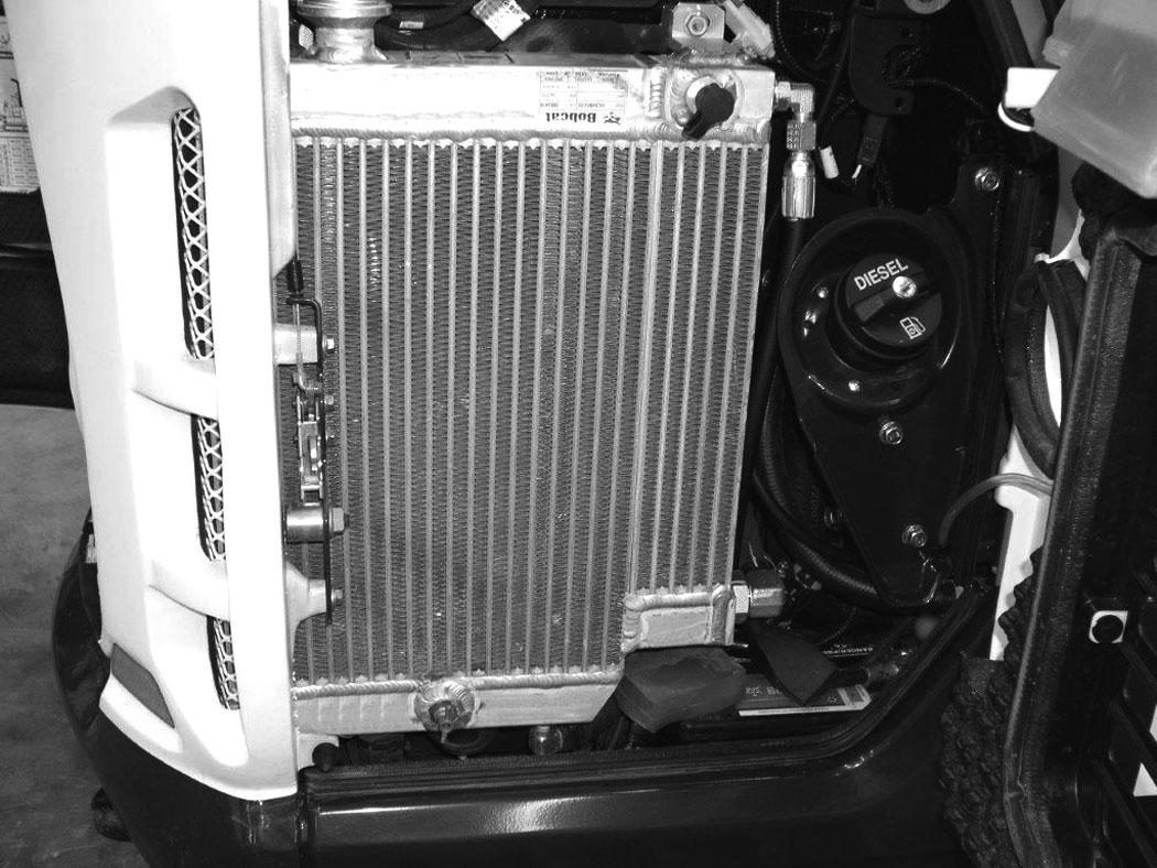
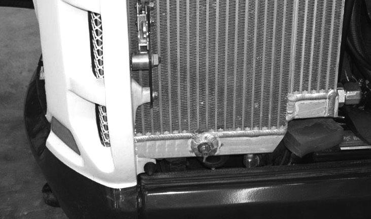
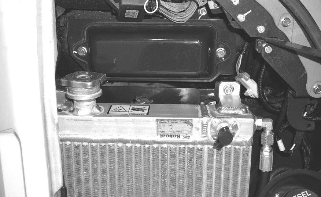
Cleaning
NOTE:This excavator uses a pusher fan so flow through the radiator / oil cooler will be from inside the engine compartment to outside the right cover. When cleaning the radiator, clean both the inside and outside surfaces of the radiator / oil cooler.
Open the tailgate. (See Opening And Closing on Page 107.)
Open the right side cover. (See Opening And Closing on Page 108.)
NOTE:Allow the cooling system and engine to cool before servicing or cleaning the cooling system.
P113446
Use air pressure or water pressure to clean the radiator / oil cooler (Item 1) [Figure 188] (both inside and outside surfaces). Be careful not to damage fins when cleaning.
Close the right side cover. (See Opening And Closing on Page 108.)
ENGINE COOLING SYSTEM (CONT’D)
Checking Level
Warning
AVOID BURNS
Do not remove radiator cap when the engine is hot. You can be seriously burned.
W-2070-1203
Warning
AVOID INJURY OR DEATH
Wear safety glasses to prevent eye injury when any of the following conditions exist:
•When fluids are under pressure.
•Flying debris or loose material is present.
•Engine is running.
•Tools are being used.
Important
AVOID ENGINE DAMAGE
W-2019-0907
Open the tailgate. (See Opening And Closing on Page 107.)
Figure 189
P113433
Check the coolant level in the coolant recovery tank (Item 1) [Figure 189]
The coolant level must be filled so it is within the MAX / MIN line marked on the coolant recovery tank.
NOTE:The cooling system is factory filled with propylene glycol (purple colour). DO NOT mix propylene glycol with ethylene glycol.
Always use the correct ratio of water to antifreeze.
Too much antifreeze reduces cooling system efficiency and may cause serious premature engine damage.
Too little antifreeze reduces the additives which protect the internal engine components; reduces the boiling point and freeze protection of the system.
Always add a premixed solution. Adding full strength concentrated coolant can cause serious premature engine damage.
I-2124-0497

ENGINE COOLING SYSTEM (CONT’D)


Removing And Replacing Coolant
See the service schedule for correct service intervals. (See SERVICE SCHEDULE on Page 101.)
Stop the engine. Open the tight side cover. (See Opening And Closing on Page 108.)
Warning
AVOID BURNS
Do not remove radiator cap when the engine is hot. You can be seriously burned.
When the engine is cool, loosen and remove the coolant fill cap (Item 1) [Figure 190]
After all the coolant is removed, close both drain valves. Recycle or dispose of the used coolant in an environmentally safe manner.
Mix the coolant in a separate container. (See Capacities on Page 163.)
NOTE:The cooling system is factory filled with propylene glycol (purple colour). DO NOT mix propylene glycol with ethylene glycol.
The correct mixture of coolant to provide a -37°C (-34°F) freeze protection is 5 L propylene glycol mixed with 4,4 L of water OR 1 U.S. gal propylene glycol mixed with 3.5 qt of water.
Add premixed coolant, 47% water and 53% propylene glycol to the coolant tank until the coolant level reaches the lower marker on the tank.
Use a refractometer to check the condition of propylene glycol in your cooling system.
Add premixed coolant until the level is correct. Install the coolant fill cap.
Run the engine until it is at operating temperature. Stop the engine. Check the coolant level when cool. Add coolant as needed. Install the coolant fill cap.
Close the tailgate.
Description
Figure 193
The excavator has a 12 volt, negative earth electrical system. The electrical system is protected by fuses located under the right side cover of the excavator (Item 1) [Figure 193]. The fuses will protect the electrical system when there is an electrical overload. The reason for the overload must be found and corrected before starting the engine again.
The battery cables must be clean and tight. Check the electrolyte level in the battery. Add distilled water as needed. Remove acid or corrosion from the battery and cables with a sodium bicarbonate and water solution.
Put Battery Saver P/N 6664458 or grease on the battery terminals and cable ends to prevent corrosion.
Warning
AVOID INJURY OR DEATH
Batteries contain acid which burns eyes and skin on contact. Wear goggles, protective clothing and rubber gloves to keep acid off body.
In case of acid contact, wash immediately with water. In case of eye contact get prompt medical attention and wash eye with clean, cool water for at least 15 minutes.
If electrolyte is taken internally drink large quantities of water or milk! DO NOT induce vomiting. Get prompt medical attention.
W-2065-0807
Fuse And Relay Location / Identification
A decal is inside the fuse cover to show location and amp ratings.
Remove the cover to check or replace the fuses and relays.

The location and amperage ratings are shown in [Figure 194].
Always replace fuses using the same type and capacity.
ELECTRICAL SYSTEM (CONT’D)

Figure 194
The location and amperage ratings are shown in the table below and on the decal [Figure 194]. Relays are identified by the letter “R” in the AMP column.
ELECTRICAL SYSTEM (CONT’D)
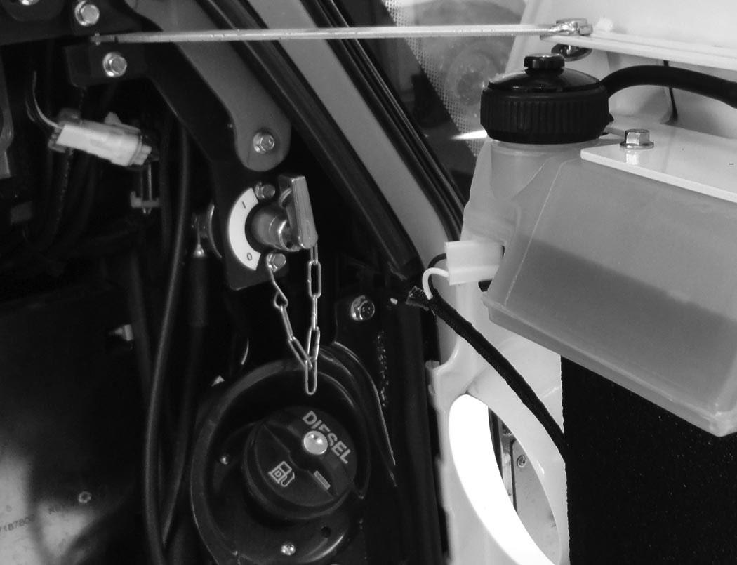
Battery Disconnect Switch
When disconnecting or connecting the battery cables, turn the disconnect switch to the OFF position first. Open the right side cover. (See RIGHT SIDE COVER on Page 108.)
The disconnect switch (Item 1) [Figure 195] is located under the right side cover, above the fuel fill cap.
Rotate the switch (Item 1) [Figure 195] anticlockwise to turn the switch to the OFF position, clockwise to turn to the ON position (shown in ON position).
NOTE:In the OFF position the shut-off switch key can be removed from the switch. The key is secured to the switch mount with a chain.
ELECTRICAL SYSTEM (CONT’D)
Battery Maintenance
See the SERVICE SCHEDULE for the correct service interval. (See SERVICE SCHEDULE on Page 101.)
The Bobcat brand battery supplied with your machine is sealed and does not require watering. Proper charging and storage are important to maximize the life of all batteries.
Warning
Avoid Injury Or Death
Batteries contain acid which burns eyes and skin on contact. Wear goggles, protective clothing and rubber gloves to keep acid off body.
In case of acid contact, wash immediately with water. In case of eye contact get prompt medical attention and wash eye with clean, cool water for at least 15 minutes.
If electrolyte is taken internally drink large quantities of water or milk! DO NOT induce vomiting. Get prompt medical attention.
W-2065-0807
Maintaining Battery Charge Level
Simple steps for reliability and long battery life:
•Keep battery posts and terminals clean [Figure 196].
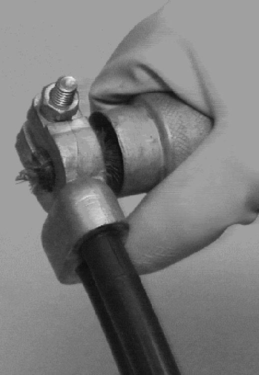
•Keep terminals tight.
•Remove corrosion from battery and terminals with sodium bicarbonate (baking soda) and water solution.
•Put Bobcat Battery Saver or grease on the battery terminals and cable ends to prevent corrosion.
•Operate the machine for at least 15 minutes to recover from the battery drain caused by engine start up whenever practical.
•Maintain the battery charge level. This is a key factor for long battery life.
•Charge a severely discharged battery with a battery charger instead of relying on the machine charging system. (See Battery Charging on Page 124.)
•Check the battery state of charge every 30 days on machines that are not frequently used. (See Battery Testing on Page 124.)
All batteries will self-discharge over time. This machine has features that require battery power even when the machine is not being used. Use of a quality battery maintainer is highly recommended to ensure that your machine is ready to start when you need it and avoid costly battery replacement.
Battery Maintainers
Use a good quality battery maintainer to keep the battery above 12.4 volts for machines that are not frequently used. Batteries below 12.4 volts must first be charged using a battery charger. Solar maintainers should have a minimum capacity of 10 watts to be effective.
Battery Service During Machine Storage
Remove the battery if storing the machine for an extended period of time. Fully charge the battery. Store the battery in a cool dry place above freezing and boost charge periodically. If battery removal is not desired, a good quality battery maintainer must be used to compensate for battery self-discharge and parasitic loads from machine controllers, accessories, and features such as connected machine intelligence.
ELECTRICAL SYSTEM (CONT’D)
Battery Testing
Figure 197
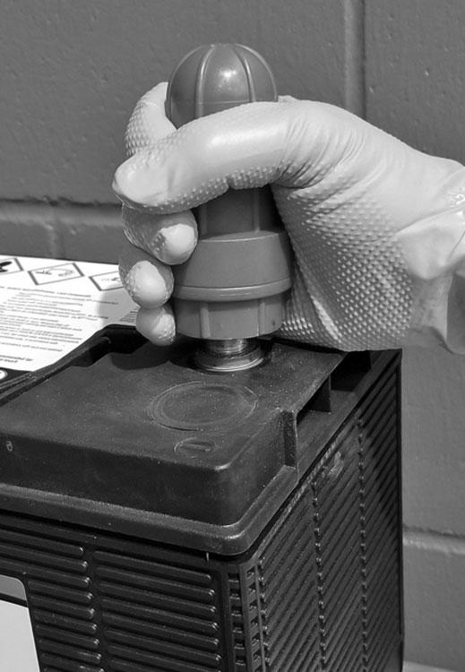
The simplest and most common check to determine battery state of charge is to use a digital multimeter or voltmeter (Item 1) [Figure 197]

A battery found below 12.4 volts must be charged to 100% charge per the battery charger’s recommendation. Allow at least 60 minutes after operating the machine or charging the battery to get an accurate reading.
If the reading is less than 12.4 volts after the battery has been charged for several hours, see your Bobcat dealer to have a more thorough battery test performed.
The freezing point of battery electrolyte is dependent on the battery state of charge. Keeping the battery voltage above 12.4 volts will help prevent batteries from freezing, even at extremely low temperatures.
If the battery freezes, the internal grid may be damaged and the case will be distorted or cracked. If this happens, dispose of the battery according to local regulations.
Battery Charging
A battery charger designed for 12 volt charging systems is recommended. Follow the battery charger manufacturer’s instructions to charge the battery to 12.6 volts (100% charge). Batteries should be charged at room temperature to avoid an undercharge or overcharge condition. Never attempt to charge a frozen battery.
The following table can be used to identify the approximate amount of time required to charge a discharged battery. Allow at least 60 minutes after operating the machine or charging the battery to get an accurate reading.
NOTE:Use a good quality automatic charger to avoid battery damage from overcharging.
BATTERY GAS CAN EXPLODE AND CAUSE SERIOUS INJURY OR DEATH
Keep arcs, sparks, flames and lighted tobacco away from batteries. When jumping from booster battery make final connection (negative) at machine frame.
Do not jump start or charge a frozen or damaged battery. Warm battery to 16°C (60°F) before connecting to a charger. Unplug charger before connecting or disconnecting cables to battery. Never lean over battery while boosting, testing or charging. W-2066-0910
ELECTRICAL SYSTEM (CONT’D)
Using A Booster Battery (Jump Starting)
Important
If jump starting the excavator from a second machine:
When jump starting the excavator from a battery installed in a second machine, make sure the engine is NOT running while using the glow plugs. High voltage spikes from a running machine can burn out the glow plugs.
I-2060-0906
If it is necessary to use a booster battery to start the engine, BE CAREFUL! There must be one person in the operator’s seat and one person to connect and disconnect the battery cables.
Be sure the key switch is OFF. The booster battery must be 12 volt.
Open the tailgate. (See Opening And Closing on Page 107.)
NOTE:To access the battery for jump starting, the battery hold-down will need to be removed and the battery moved outward to access the positive battery post.
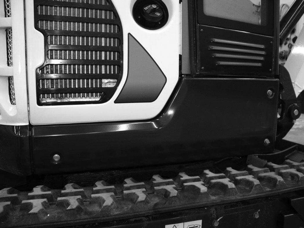
Remove
Remove the three bolts (Item 1) and remove the right side lower cover (Item 2) [Figure 198]
Open the right side cover. (See Opening And Closing on Page 108.)
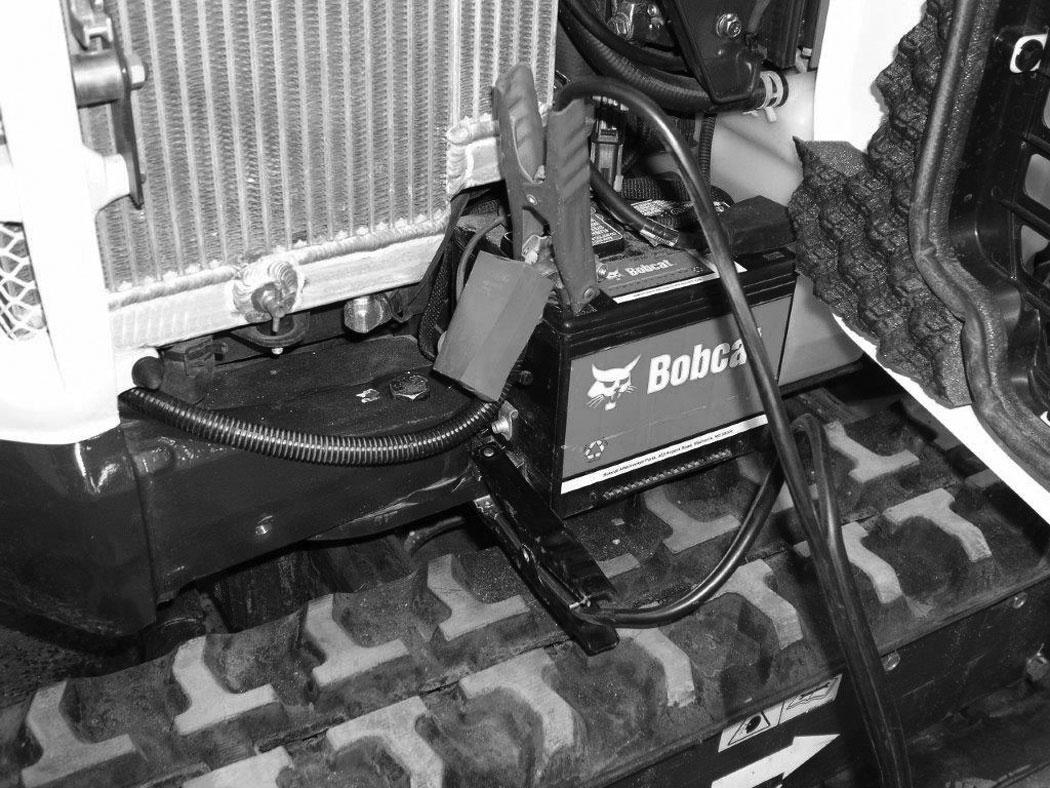
Connect one end of the first cable to the positive (+) terminal of the booster battery. Connect the other end of the same cable to the positive (+) terminal (Item 1) [Figure 198] of the excavator battery.

Connect one end of the second cable to the negative (-) terminal of the booster battery. Connect the other end of the same cable to a frame earth point (Item 2) [Figure 200]
Start the engine. After the engine has started, remove the negative (-) cable first (Item 1) [Figure 200]
Disconnect the cable from the excavator starter (Item 1) [Figure 198].
ELECTRICAL SYSTEM (CONT’D)
Using A Booster Battery (Jump Starting) (Cont’d)
Replace the positive battery cable cover and push the battery in fully. Reinstall the battery hold-down plate (Item 2) and the two bolts (Item 1) [Figure 199]
Reinstall the lower right side cover [Figure 198]
NOTE:(See Cold Temperature Starting on Page 67.)
Important
Damage to the alternator can occur if:
•Engine is operated with battery cables disconnected.
•Battery cables are connected when using a fast charger or when welding on the excavator. (Remove both cables from the battery.)
•Extra battery cables (booster cables) are connected wrong.
I-2223-0903
ELECTRICAL SYSTEM (CONT’D)
Removing And Installing The Battery
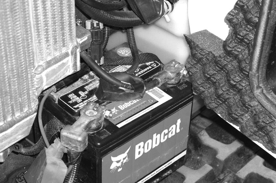
Figure 201
Remove the three bolts (Item 1) and remove the right side lower cover (Item 2) [Figure 201].
Open the right side cover. (See Opening And Closing on Page 108.)
Turn the battery disconnect switch to the OFF position. (See Battery Disconnect Switch on Page 122.)
Figure 202
Remove the two bolts (Item 1) and remove the battery hold-down plate (Item 2) [Figure 202]
Slide the battery to the right to access the battery cables.
Disconnect the negative (-) cable (Item 1) [Figure 203] first.
Disconnect the positive (+) cable (Item 2) [Figure 203]
Remove the battery.
Always clean the terminals and the cable ends, even when installing a new battery.
Position the battery into the battery box. Connect the battery cables. Connect the negative (-) cable (Item 1) [Figure 203] last to prevent sparks. Reinstall the battery post covers and slide the battery in fully.
Tighten the terminal clamp nuts to 7 N•m (5 ft-lb) torque. Install the hold-down plate (Item 2) and the two bolts (Item 1) [Figure 198]. Reinstall the lower cover [Figure 201].
Turn the battery disconnect switch to the ON position. (See Battery Disconnect Switch on Page 122.)
Warning
Avoid Injury Or Death
Batteries contain acid which burns eyes and skin on contact. Wear goggles, protective clothing and rubber gloves to keep acid off body.
In case of acid contact, wash immediately with water. In case of eye contact get prompt medical attention and wash eye with clean, cool water for at least 15 minutes.
If electrolyte is taken internally drink large quantities of water or milk! DO NOT induce vomiting. Get prompt medical attention.
Hydraulic System
Checking And Adding Hydraulic Fluid
Put the machine on a flat level surface.
Retract the arm and bucket cylinders, put the bucket on the ground and lower the blade. Stop the engine.
Open the right side cover. (See Opening And Closing on Page 108.)
Warning
Avoid Injury Or Death
Always clean up spilled fuel or oil. Keep heat, flames, sparks or lighted tobacco away from fuel and oil. Failure to use care around combustibles can cause explosion or fire.
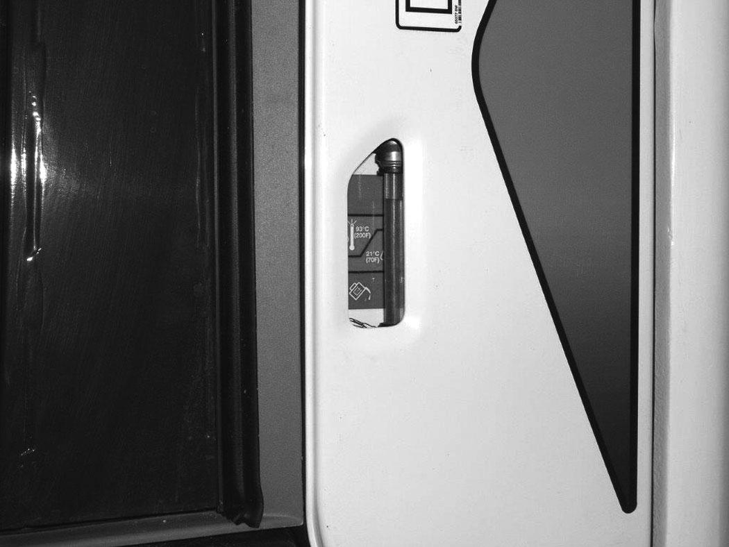
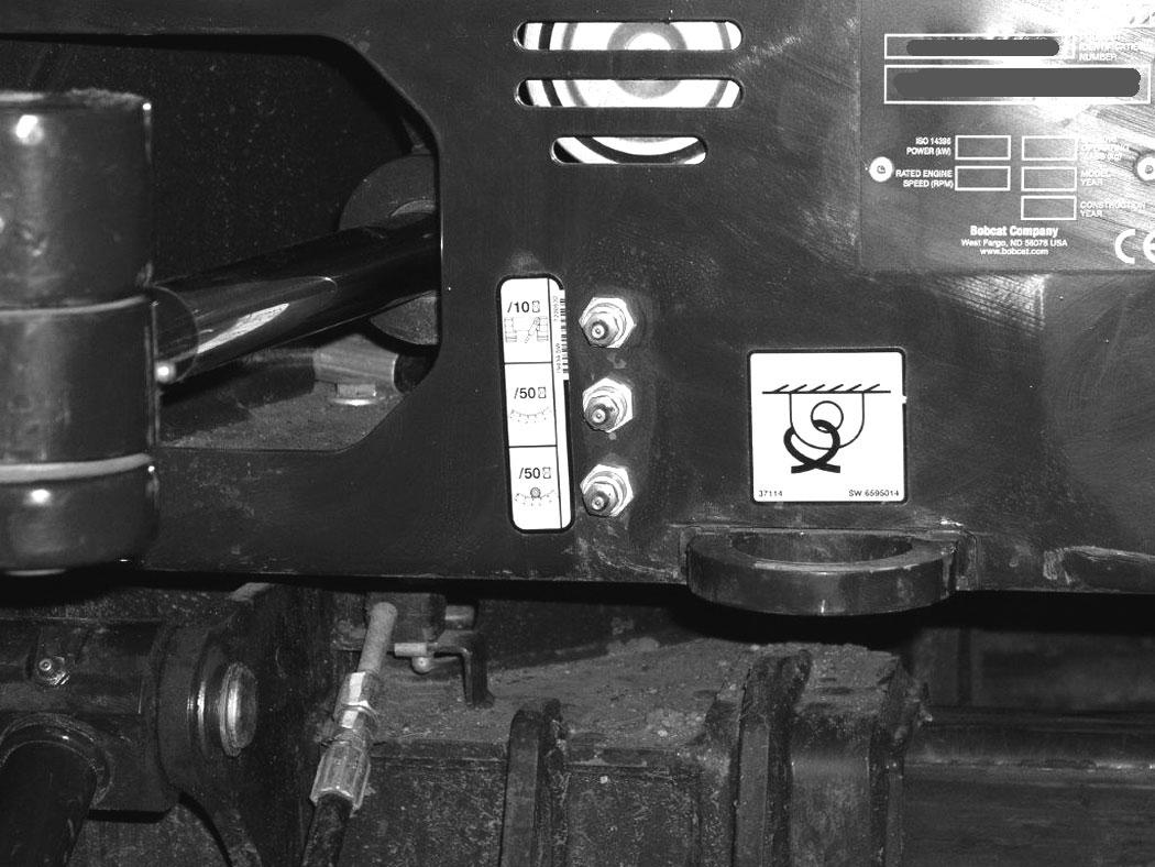
Park the machine in the position shown [Figure 204] (The preferred method is to check the hydraulic fluid when it is cold.)

Check the hydraulic fluid level, it must be visible in the sight gauge (Item 1) [Figure 204]. The decal on the hydraulic tank shows the correct fill level.

A - Correct Oil Level COLD (Preferred)
B - Correct Oil Level HOT (Optional)
Remove screw (Item 1) [Figure 205] from the top of the cover and remove the left side cover.
Clean the surface around the reservoir cap and remove the cap from the reservoir (Item 2) [Figure 205]
Check the condition of the fill strainer screen (Item 3) [Figure 205]. Clean or replace as necessary.
Be sure the screen is installed before adding fluid.
Add the correct fluid to the reservoir until it is visible in the sight gauge.
Check the cap and clean as necessary. Replace the cap if damaged.
Install the cap.
Close the right side cover and tailgate.
HYDRAULIC SYSTEM (CONT’D)
Hydraulic / Hydrostatic Fluid Chart
Figure 206
HYDRAULIC / HYDROSTATIC FLUID RECOMMENDED ISO VISCOSITY GRADE (VG) AND VISCOSITY INDEX (VI)
Removing And Replacing The Hydraulic Filters
Warning
AVOID INJURY OR DEATH
Always clean up spilled fuel or oil. Keep heat, flames, sparks or lighted tobacco away from fuel and oil. Failure to use care around combustibles can cause explosion or fire.
W-2103-0508
Hydraulic Filter
See the service schedule for the correct service interval. (See SERVICE SCHEDULE on Page 101.)
TEMPERATURE RANGE ANTICIPATED DURING MACHINE USE
[1] VG 100; Minimum VI 130
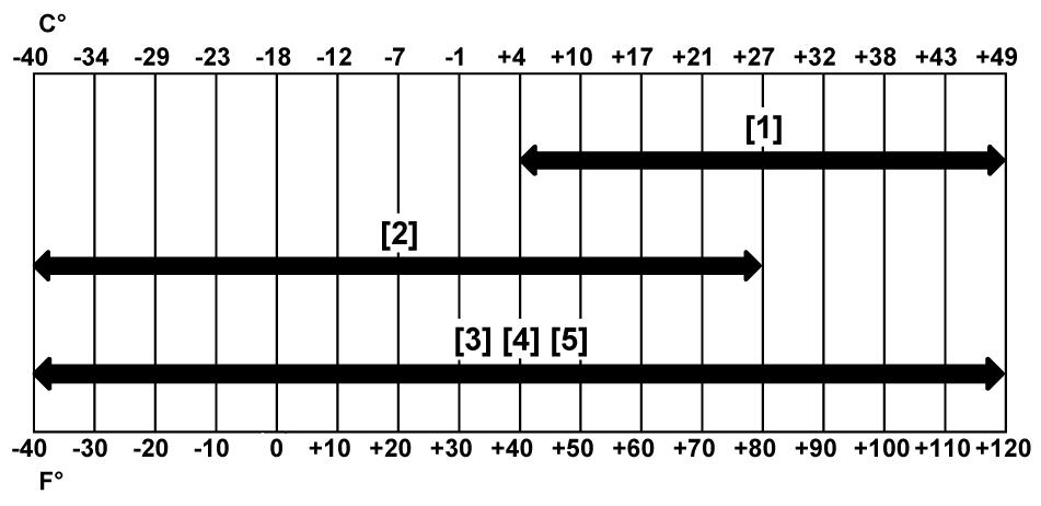
[2] VG 46; Minimum VI 150
[3] BOBCAT All-Season Fluid
[4] BOBCAT Synthetic Fluid
[5] BOBCAT Biodegradable Hydraulic / Hydrostatic Fluid (Unlike biodegradable fluids that are vegetable based, Bobcat biodegradable fluid is formulated to prevent oxidation and thermal breakdown at operating temperatures.)
Install the oil fill cap.
Open the tailgate. (See Opening And Closing on Page 107.)
P134093
Remove the hydraulic filter (Item 1) [Figure 207]
Clean the housing where the filter gasket makes contact. Put clean hydraulic fluid on the gasket. Install the new filter and hand tighten only. Use a genuine Bobcat replacement filter.
Warning
AVOID INJURY OR DEATH
Always clean up spilled fuel or oil. Keep heat, flames, sparks or lighted tobacco away from fuel and oil. Failure to use care around combustibles can cause explosion or fire.
W-2103-0508
HYDRAULIC SYSTEM (CONT’D)
Removing And Replacing The Hydraulic Fluid
See the service schedule for the correct service interval. (See SERVICE SCHEDULE on Page 101.)
Warning
AVOID INJURY OR DEATH
Diesel fuel or hydraulic fluid under pressure can penetrate skin or eyes, causing serious injury or death. Fluid leaks under pressure may not be visible. Use a piece of cardboard or wood to find leaks. Do not use your bare hand. Wear safety goggles. If fluid enters skin or eyes, get immediate medical attention from a doctor familiar with this injury.
W-2072-EN-0909
Retract the arm and bucket cylinders, lower the bucket to the ground. Stop the engine.
Open the tailgate. (See Opening And Closing on Page 107.)
With the engine OFF, loosen the plug (Item 1) [Figure 209] on the hydraulic pump. Tighten the plug after a steady stream of hydraulic fluid, free of any air bubbles, drains from the plug. DO NOT RUN THE MACHINE WITH THE PLUG OPEN. Tighten the plug to 30 – 34 N•m (22 – 25 ft-lb) torque.
The hydraulic fluid drain plug (Item 1) [Figure 208] is located on the hydraulic pump inlet fitting.
Remove the plug (Item 1) [Figure 208]
Drain the fluid into a container.
Recycle or dispose of the fluid in an environmentally safe manner.
Install the plug (Item 1) [Figure 208]
Add fluid to the reservoir. (See Checking And Adding Hydraulic Fluid on Page 128.)
There is also a port (Item 1) [Figure 210] on the hydraulic cooler for bleeding air. Install a diagnostic coupler and hose on this fitting to allow air to be bleed from the hydraulic system after the hydraulic fluid has been replaced. Remove the hose and coupler before starting the engine.

Start the engine and operate the machine through the hydraulic functions. Stop the engine. Check the fluid level and add as needed.

SPARK ARRESTER MUFFLER Cleaning Procedure
See the SERVICE SCHEDULE for the correct service interval. (See SERVICE SCHEDULE on Page 101.)
Warning
Avoid Injury Or Death
When an engine is running in an enclosed area, fresh air must be added to avoid concentration of exhaust fumes. If the engine is stationary, vent the exhaust outside. Exhaust fumes contain odorless, invisible gases which can kill without warning.
W-2050-0807
Warning
Stop engine and allow the muffler to cool before cleaning the spark chamber. Wear safety goggles. Failure to obey can cause serious injury.
W-2011-1285
Important
This machine is factory equipped with a spark arrester exhaust system.
The spark arrester muffler, if equipped, must be cleaned to keep it in working condition. The spark arrester muffler must be serviced by dumping the spark chamber every 100 hours of operation.
On some models, the turbocharger functions as the spark arrester and must operate correctly for proper spark arrester function.
If this machine is operated on flammable forest, brush, or grass covered land, a spark arrester attached to the exhaust system may be required and must be maintained in working order. Refer to local laws and regulations for spark arrester requirements.
I-2284-EN-0909
Warning
Never use machine in atmosphere with explosive dust or gases or where exhaust can contact flammable material. Failure to obey warnings can cause injury or death.
W-2068-1285
Warning
When the engine is running during service, the steering levers must be in neutral.
Failure to do so can cause injury or death.
W-2203-0595
Do not operate the excavator with a defective exhaust system.
Stop the engine. Open the tailgate. (See TAILGATE on Page 107.)
Remove the left side cover.
Figure 211
Remove the plug (Item 1) [Figure 211] from the bottom of the muffler.
Start the engine and run for about 10 seconds while a second person, wearing safety glasses, holds a piece of wood over the outlet of the muffler. The carbon deposits will be forced out of the muffler plug hole (Item 1) [Figure 211]
Stop the engine. Install and tighten the plug.
Close the tailgate.
TRACK TENSION
Checking Tension
NOTE:The wear of the pins and bushings on the undercarriage vary with the working conditions and the different types of soil conditions. It is necessary to inspect track tension and maintain the correct tension. See service schedule for the correct service interval. (See SERVICE SCHEDULE on Page 101.)
Raise the side of the machine (approximately 102 mm [4 in]) using the boom and arm.
Warning
AVOID INJURY
Keep fingers and hands out of pinch points when checking the track tension.
W-2142-0903
Track Clearance
Raise the blade fully and install jackstands under the blade and track frame (Item 1) [Figure 212] and [Figure 213]. Raise the boom until all machine weight is on the jackstands.

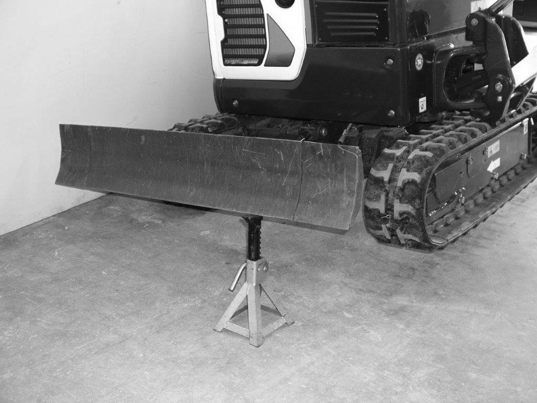
Stop the engine.
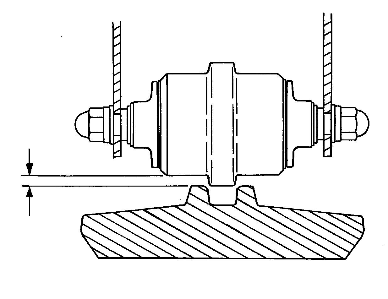
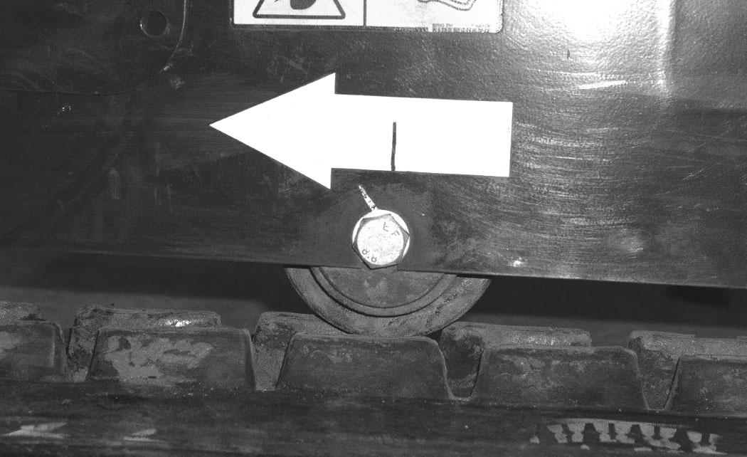
Measure the clearance at either middle track roller. Do not get fingers into pinch points between the track and the track roller. Use a bolt or a dowel of the appropriate size to check the gap between the contact edge of the roller and the top edge of the track guide [Figure 214] and [Figure 215]
- 0.53
TRACK TENSION (CONT’D)
Adjusting Tension
Figure 216
Loosen the access cover bolts and pivot the access cover open [Figure 216]
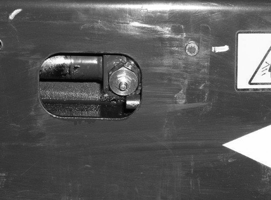
Increase Track Tension
Add grease to the fitting (Item 1) [Figure 216] until the track tension is correct.
If grease fitting is removed before pressure is released, the fitting can come off with great force and cause serious injury or death.
W-2490-0104
Pressure must be released from the grease cylinder to decrease track tension.
Loosen the bleed fitting (NOT the grease fitting) (Item 2) [Figure 216] and release pressure until the track tension is correct.
NOTE:DO NOT loosen the bleed fitting (Item 2) [Figure 216] for more than eight turns.
Tighten the bleed fitting to 80 – 100 N•m (59 – 74 ft-lb) torque.
Pivot the access cover closed and tighten the access cover bolts.
Raise the machine and remove the jackstands.
Repeat the procedure for the other side.
Dispose of grease in an environmentally safe manner.
Travel Motor
Checking And Adding Oil
Figure 217
Park the excavator on a level surface with the plugs (Items 1 and 2) [Figure 217] in the position as shown.
Remove the plug (Item 1) [Figure 217]. The fluid level must be at the bottom edge of the hole.
Add lubricant (SAE 80W90) through the hole if the fluid level is low.
Removing And Replacing Oil
See the service schedule for the correct service interval. (See SERVICE SCHEDULE on Page 101.)
Park the excavator on a level surface with plugs (Items 1 and 2) [Figure 217] in the position shown. Remove both plugs and drain the lubricant into a container.

Warning
Avoid Injury Or Death
Always clean up spilled fuel or oil. Keep heat, flames, sparks or lighted tobacco away from fuel and oil. Failure to use care around combustibles can cause explosion or fire.
Install the bottom plug (Item 2) [Figure 217]. Add fluid through the centre plug hole until the fluid level is at the bottom edge of the hole.
Install the plug (Item 1) [Figure 217]
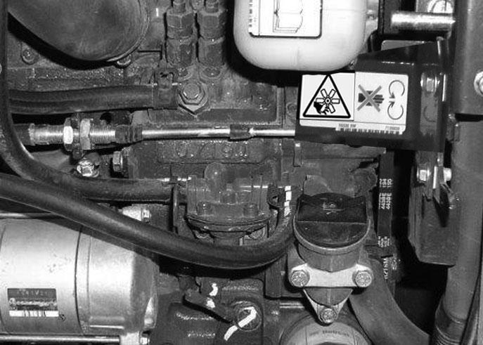
Alternator And Fan Belt
Belt Adjustment
Stop the engine and open the tailgate. (See Opening And Closing on Page 107.)
Measure the belt (Item 1) [Figure 218] tension at the middle of the belt span.
If a belt tension tool is available, move the alternator until the belt has (new belt = 272 - 292 N [61 - 65 lbf] or used belt = 233 - 252 N [53 - 57 lbf]) tension.
If a belt tension tool is not available, move the alternator until the belt has 8,0 mm (5/16 in) movement at the middle of the belt span with 66 N (15 lbf) of force.
NOTE:The seat is shown removed for photo clarity. The alternator adjusting bolts can be accessed by removing the belt guard (Item 2) [Figure 218] and reaching around the engine.

If the belt tension is not correct, loosen the bolt and nut (Item 1) and the bolt (Item 2) [Figure 219] until the alternator can be moved toward the engine.
Adjust belt tension to correct specifications [Figure 218].
Tighten the mounting and adjustment bolts.
Close the tailgate.
Belt Replacement
Loosen the bolt and nut (Item 1) and the bolt (Item 2) [Figure 219] until the alternator can be moved toward the engine.
Remove the old belt and install a new belt.
Adjust belt tension to correct specifications [Figure 218]
Tighten the mounting and adjustment bolts.
Reinstall the belt guard (Item 2) [Figure 218]
Close the tailgate.
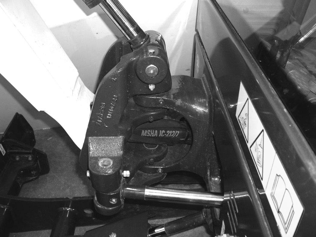
Quick Coupler
Bucket Link And Attachment Coupler Inspection And Maintenance
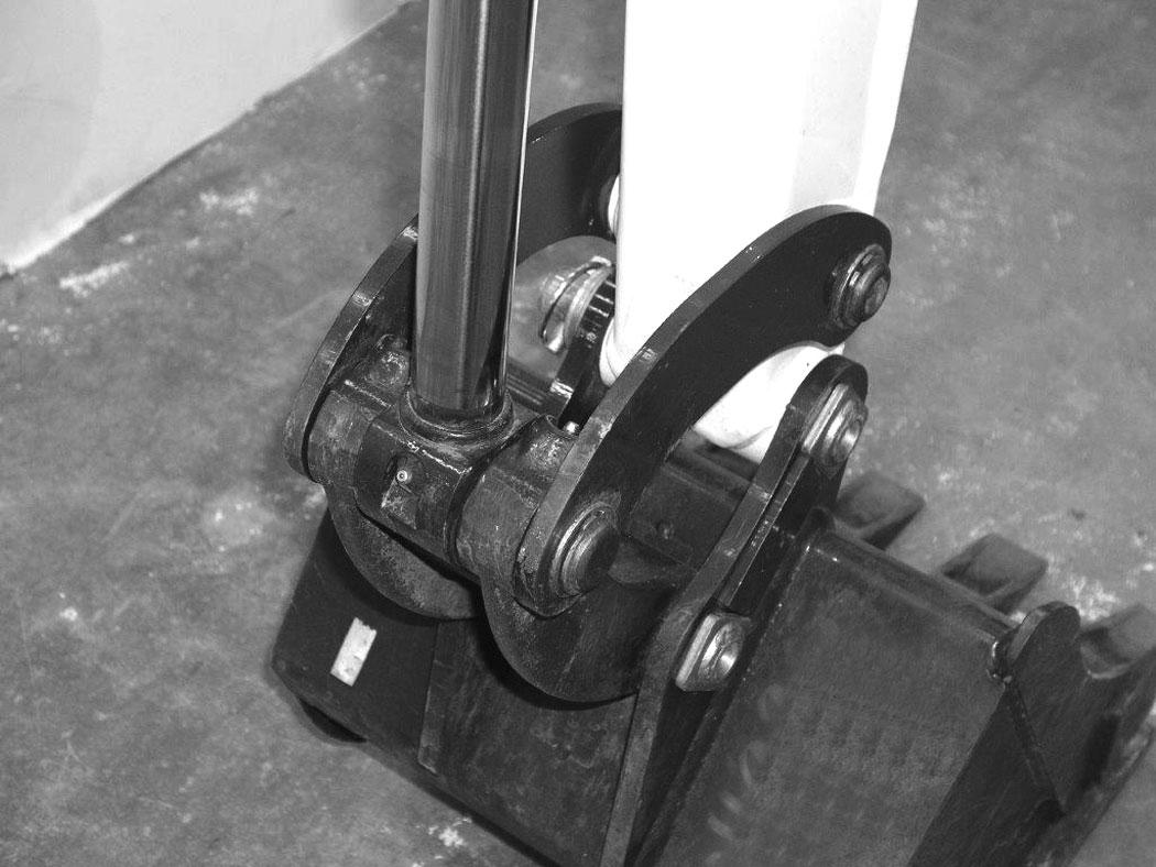
Figure 220
Inspect the bucket link (Item 1) for wear or damage. Inspect the attachment pins (Item 2) [Figure 220] for wear or damage.
Repair or replace damaged parts.
221
Inspect the quick coupler for wear or damage. Inspect the quick coupler pins (Item 1) and the hooks (Item 2) [Figure 221] (on the attachment) for wear or damage

Repair or replace damaged parts.
TRACK ROLLER AND IDLER LUBRICATION Procedure
The track rollers and idlers require no maintenance. The bearings are a sealed design.

Lubrication Of The Hydraulic Excavator
Lubrication Locations
Lubricate the excavator as specified in the service schedule for the best performance of the machine. (See SERVICE SCHEDULE on Page 101.)

Always use a good quality lithium based multipurpose grease when lubricating the machine. Apply the lubricant until extra grease shows.
Lubricate the following locations on the excavator EVERY 8 – 10 HOURS:
LUBRICATION OF THE HYDRAULIC EXCAVATOR (CONT’D)


Lubrication Locations (Cont’d)
LUBRICATION OF THE HYDRAULIC EXCAVATOR (CONT’D)
Lubrication Locations (Cont’d)
Figure 229
17.Cab Door hinges (3) [Figure 229] (if equipped)
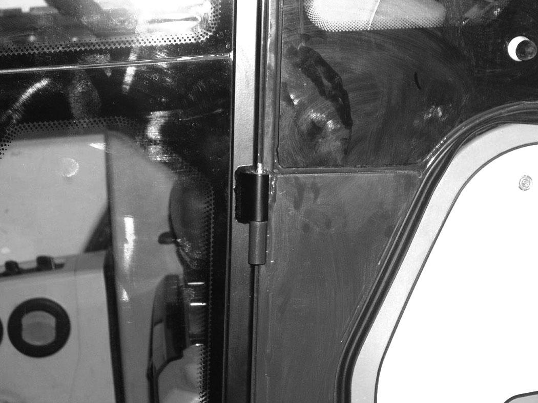
Figure 230
18.Boom Swing Cylinder Base (1) [Figure 230]
Lubricate the following locations on the hydraulic excavator EVERY 50 HOURS:
19.Slew Circle (1) [Figure 230]
20.Slew Pinion (1) [Figure 230]. (Install three to four pumps of grease then rotate the upperstructure 90°. Install three to four pumps of grease and again rotate the upperstructure 90°. Repeat this until the slew pinion has been greased at four positions.)
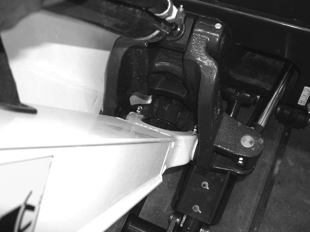
PIVOT PIN
Inspection And Maintenance
Figure 231
The pivots and cylinders (Item 1) have a large pin held in position with a bolt (Item 2) and double nuts (Item 3) [Figure 231] securing the pin.
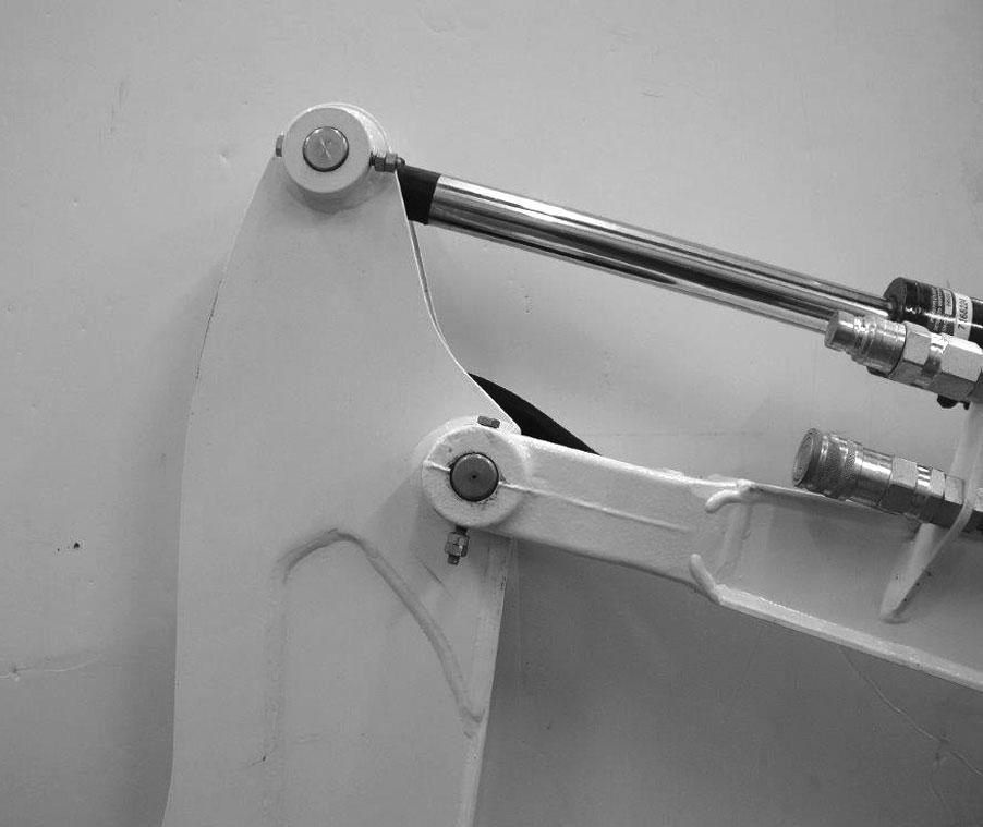
The two nuts (Item 3) are used as jam nuts to hold the bolt (Item 2) without tightening the bolt (Item 2) to the pin boss. After the nuts (Item 3) are tightened together, the bolt (Item 2) [Figure 231] should be free to spin. See your Bobcat dealer for replacement parts.
EXCAVATOR STORAGE AND RETURN TO SERVICE Storage
Sometimes it can be necessary to store your Bobcat excavator for an extend period of time. Below is a list of items to perform before storage.
•Thoroughly clean the excavator including the engine compartment.
•Lubricate the excavator.
•Replace worn or damaged parts.
•Drive the excavator onto planks in a dry protected shelter.
•Lower the boom fully with the bucket flat on the ground.
•Put grease on any exposed cylinder rods.
•Put fuel stabiliser in the fuel tank and run the engine a few minutes to circulate the stabiliser to the pump and fuel injectors.
•Drain and flush the cooling system. Refill with premixed coolant.
•Replace all fluids and filters (engine, hydraulic).
•Replace all filters (For example: air cleaner, heater, etc.).
•Put all controls in NEUTRAL position.
•Remove the battery. Be sure the electrolyte level is correct then charge the battery. Store it in a cool dry place above freezing temperatures and charge it periodically during storage.
•Cover the exhaust pipe opening.
•Tag the machine to indicate that it is in storage condition.
Return To Service
After the Bobcat excavator has been in storage, it is necessary to follow a list of items to return the excavator to service.
•Check the engine and hydraulic fluid levels; check coolant level.
•Install a fully charged battery.
•Remove grease from exposed cylinder rods.
•Check all belt tensions.
•Be sure all shields and guards are in place.
•Lubricate the excavator.
•Remove cover from exhaust pipe opening.
•Start the engine and let run for a few minutes while observing the instrument panels and systems for correct operation.
•Drive the excavator off of the planks.
•Operate machine, check for correct function.
•Stop the engine and check for leaks. Repair as needed.
Diagnostic Service Codes
Viewing Service Codes
The Service Codes will aid your dealer in diagnosing conditions that can damage your machine.
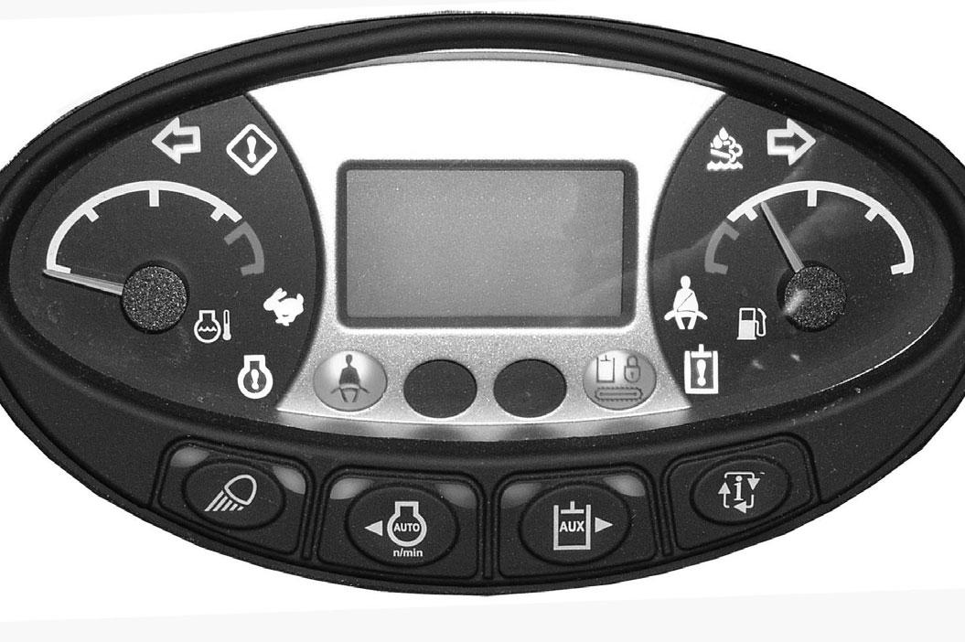
Press the Information button (Item 2) to cycle the data display (Item 1) [Figure 232] until the service code screen is displayed. If more than one service code is present, the codes will scroll on the data display.
When no service code is present, [NONE] is displayed [Figure 232]
NOTE:Corroded or loose earth can cause multiple service codes and / or abnormal symptoms. All instrument panel lights flashing, alarm sounding, headlights and taillights flashing, can indicate a bad earth. The same symptoms can apply if the voltage is low, such as loose or corroded battery cables. If you observe these symptoms, check earth and positive leads first.
DIAGNOSTIC SERVICE CODES (CONT'D)
DIAGNOSTICS SERVICE CODE (CONT’D)
PASSWORD SETUP (KEYLESS START PANEL)
Password Description
Master Password:
A permanent, randomly selected password set at the factory that cannot be changed. This password is used for service by the Bobcat dealer if the owner password is not known or to change the owner password.
Owner Password:
Allows for full use of the excavator. Must be used to change the owner password, or User 1 / User 2 password.
User 1 And User 2 Passwords:
By default, User 1 ad User 2 Passwords are not set.
NOTE:The User 1 and User 2 Password cannot be used to change a password or to switch between the Locked / Unlocked models.
Changing The Owner, User 1 And User 2 Password
Turn the start switch (Item 1) [Figure 233] to the ON position to turn on the excavators electrical system.
Enter the five digit owner password using the number keys (1 through 0) if locked.

Figure 233
Press and hold the lock (Item 2) and unlock (Item 3) [Figure 233] keys for 2 seconds.
The lock key red light or the unlock key green light will flash and the instrument panel display screen will show [CODE]
Enter a new five digit owner password using the number keys (1 through 0).
The display screen will show [OWNER] for two seconds. Press the unlock key (Item 3) [Figure 233] to navigate between [OWNER], [USER 1], and [USER 2]
After two seconds, the display screen will show [ENTER]
NOTE:The lock key (Item 2), red light and the unlock key (Item 3)[Figure 233], green light with flash during the procedure.
Enter a new five digit owner, user 1 or user 2 password using the number keys (1 through 0). An asterisk will show in the display screen for each key pass.
The display screen will show [AGAIN]
Enter the new five digit owner password again.
The display screen will show [ERROR] if:
•The second five digit owner, user 1 or user 2 password is different from the first one entered. or
•No number key was pressed for more than 20 seconds. or
•“00000” was entered as owner, user 1 or user 2 password.
NOTE:“00000” is not an acceptable owner, user 1 or user 2 password.
The system returns to its previous state. Either the lock key (Item 2), red light or the unlock key (Item 3) [Figure 233], green light will become solid.
PASSWORD SETUP (KEYLESS START PANEL) (CONT’D)
Password Lockout Feature
This feature allows the owner to unlock the password feature so that a password does not need to be used every time the engine is started.
NOTE:The password lockout feature does not function with the user 1 or user 2 password.
Turn the start switch (Item 1) [Figure 234] to the ON position to turn on the excavators electrical system.
Enter the five digit owner password using the number keys (1 through 0).
Figure 234
Press the unlock key (Item 2) [Figure 234].
The left panel display screen will show [CODE]
Enter the five digit owner password using the number keys (1 through 0). The unlock key green light will flash, then become solid.
The excavator can now be started without using a password.
NOTE:Use the following procedure to reset the machine lock so that the excavator requires a password to start the engine.
Turn the start switch to the ON position to turn on the excavators electrical system.
Press the lock key (Item 3) [Figure 234].
The lock key red light will flash and the left panel display screen will show [CODE]
Enter the five digit owner password using the number keys (1 through 0). The unlock key green light will flash, then the lock key red light will become solid.
You must now enter the password every time to start the excavator.
MAINTENANCE CLOCK Description
The Maintenance Clock alerts the operator when the next service interval is due. EXAMPLE: The maintenance clock can be set to a 500 hour interval as a reminder for the next 500 hour planned maintenance.
Standard Instrument Panel
Figure 235
During machine operation, a 2 beep alarm will sound when there are less than 10 hours until the next planned maintenance.
The remaining hours before maintenance is required (Item 1) will appear in the data display for 5 seconds while the service icon (Item 3) and the hourmeter icon (Item 2) [Figure 235] flash.
NOTE:The display will show negative numbers after counting down to zero.
The display will revert to the previous display and will appear for 5 seconds every time the machine is started until the maintenance clock is reset.
Setup
See your Bobcat dealer about installation of this feature.
Reset
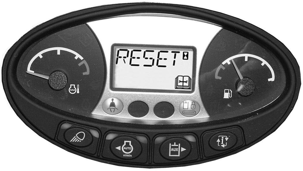
Figure 236
Press the Information button (Item 2) [Figure 236] until the display screen shows the maintenance clock.
Press and hold the Information button (Item 2) for 7 seconds until [RESET] (Item 1) [Figure 236] appears in the display screen.

Certain specification(s) are based on engineering calculations and are not actual measurements. Specification(s) are provided for comparison purposes only and are subject to change without notice. Specification(s) for your individual Bobcat equipment will vary based on normal variations in design, manufacturing, operating conditions, and other factors.
Excavator Specifications
•Where applicable, specification conform to SAE or ISO standards and are subject to change without notice.
EXCAVATOR SPECIFICATIONS (CONT’D)

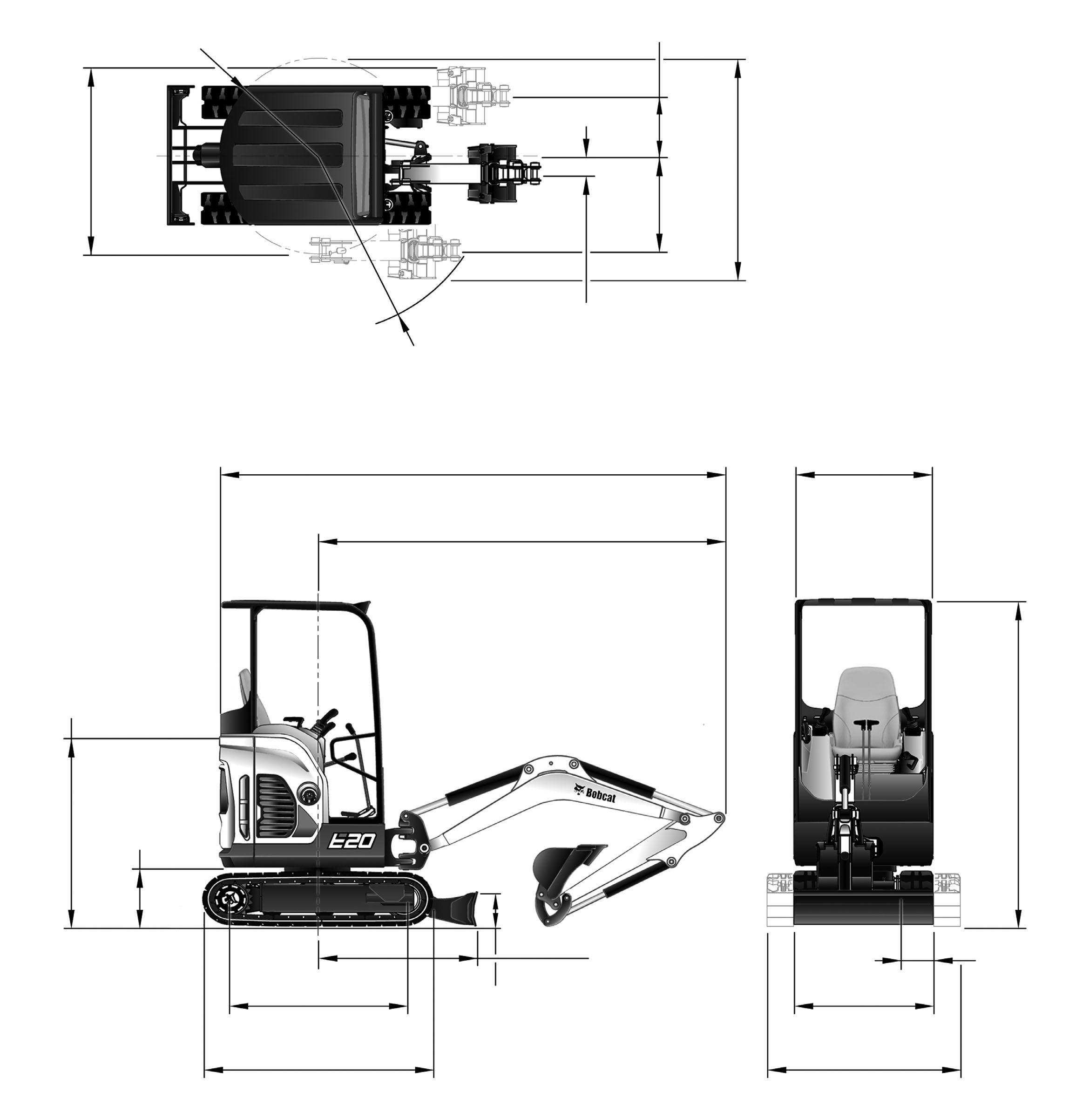
Machine Dimensions (Standard Arm)
•Where applicable, specification conform to SAE or ISO standards and are subject to change without notice.
EXCAVATOR SPECIFICATIONS (CONT’D)
Machine Dimensions (Long Arm)
•Where applicable, specification conform to SAE or ISO standards and are subject to change without notice.
EXCAVATOR SPECIFICATIONS (CONT’D)
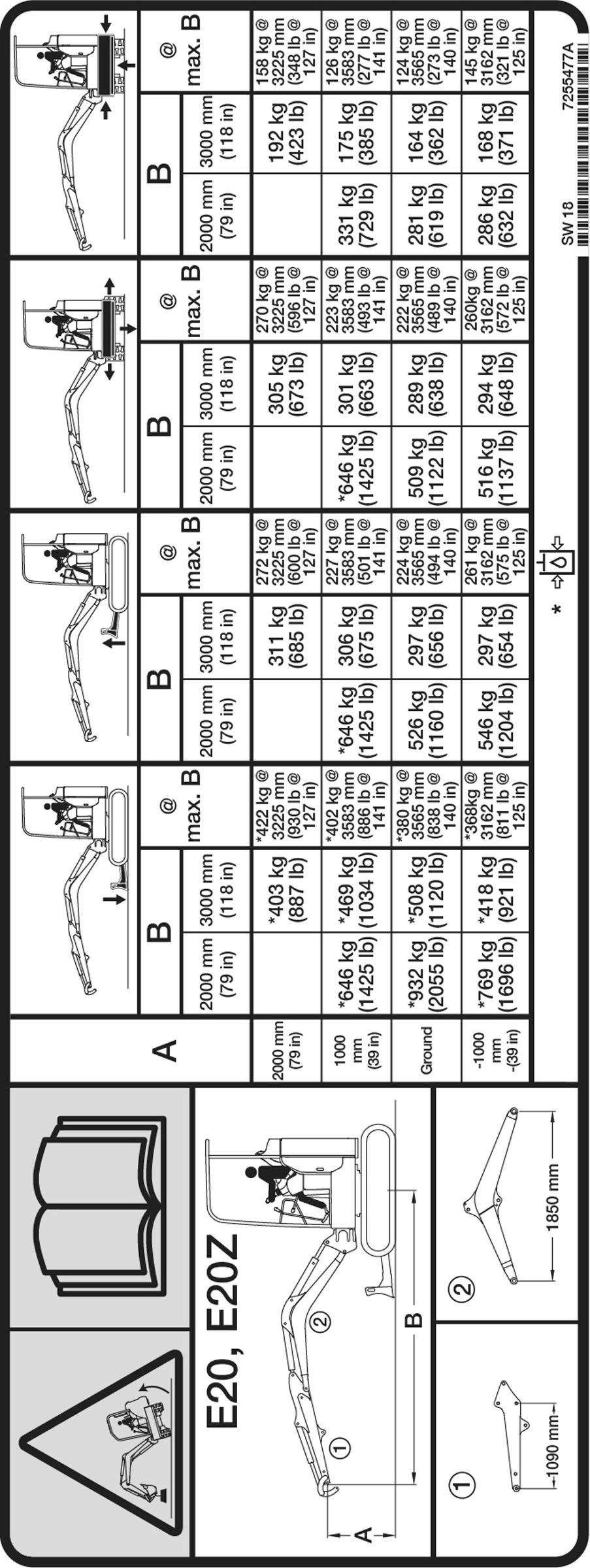
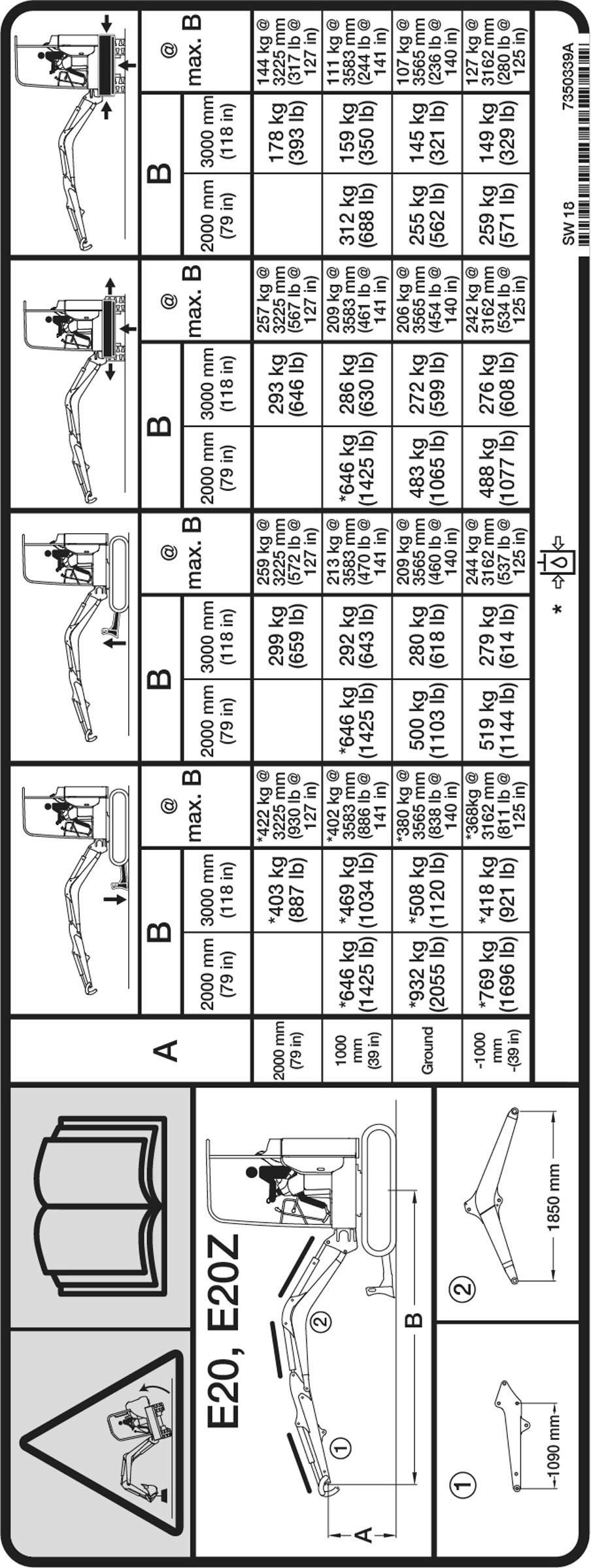
Rated Lift Capacity - With Standard Arm And Canopy (No Demolition Kit)
•Where applicable, specification conform to SAE or ISO standards and are subject to change without notice.
7255477
EXCAVATOR SPECIFICATIONS (CONT’D)
Rated Lift Capacity - With Standard Arm And Canopy (With Demolition Kit)
•Where applicable, specification conform to SAE or ISO standards and are subject to change without notice. 7350339
EXCAVATOR SPECIFICATIONS (CONT’D)
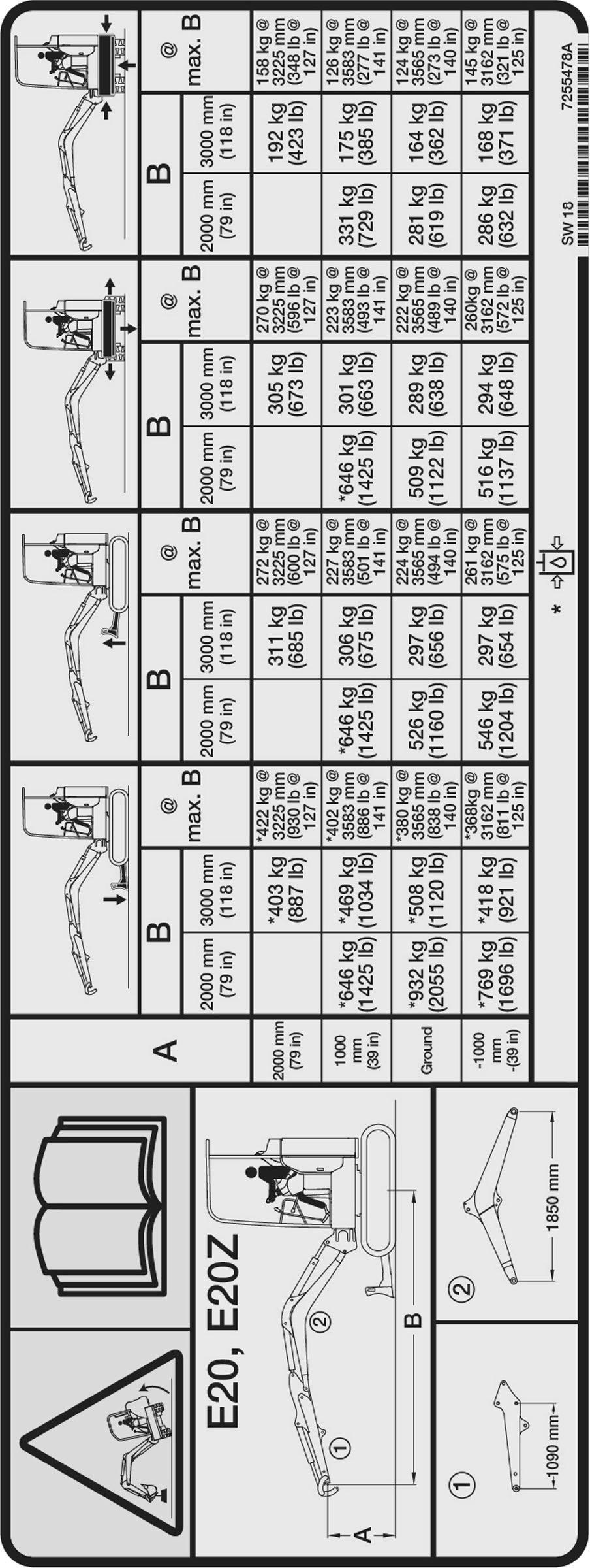
Rated Lift Capacity - With Standard Arm And Cab (No Demolition Kit)
•Where applicable, specification conform to SAE or ISO standards and are subject to change without notice.
7255478
EXCAVATOR SPECIFICATIONS (CONT’D)

Rated Lift Capacity - With Standard Arm And Cab (With Demolition Kit)
•Where applicable, specification conform to SAE or ISO standards and are subject to change without notice. 7350342
EXCAVATOR SPECIFICATIONS (CONT’D)

Rated Lift Capacity - With Long Arm And Canopy (No Demolition Kit)
•Where applicable, specification conform to SAE or ISO standards and are subject to change without notice.
7255479
EXCAVATOR SPECIFICATIONS (CONT’D)

Rated Lift Capacity - With Long Arm And Canopy (With Demolition Kit)
•Where applicable, specification conform to SAE or ISO standards and are subject to change without notice. 7350345
EXCAVATOR SPECIFICATIONS (CONT’D)
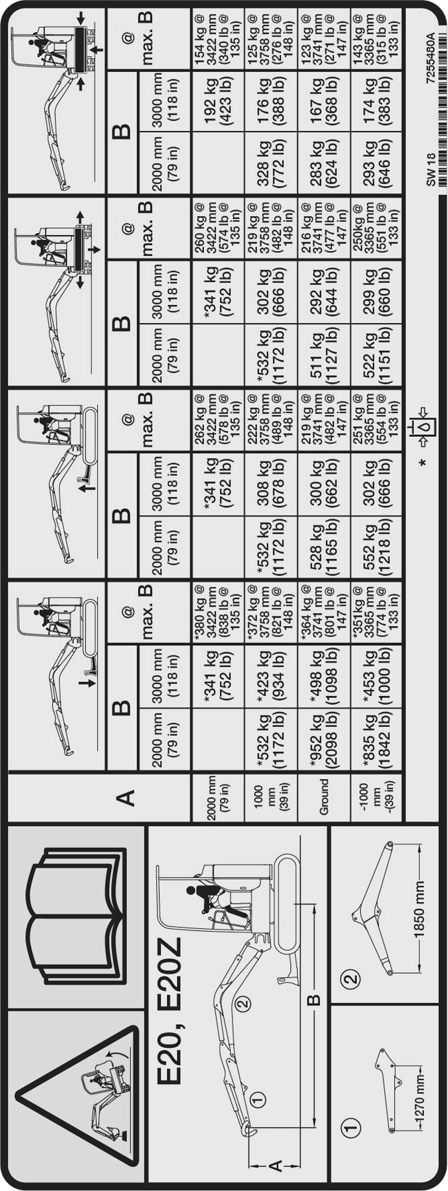
Rated Lift Capacity - With Long Arm And Cab (No Demolition Kit)
•Where applicable, specification conform to SAE or ISO standards and are subject to change without notice.
7255480
EXCAVATOR SPECIFICATIONS (CONT’D)

Rated Lift Capacity - With Long Arm And Cab (With Demolition Kit)
•Where applicable, specification conform to SAE or ISO standards and are subject to change without notice.
7350348
EXCAVATOR SPECIFICATIONS (CONT’D)
Performance
Operating weight (canopy w/ rubber tracks standard arm, standard blade, basic seat, standard bucket and 75 kg operator)
If equipped with the following:
1930 kg (4255 lb)
Cab w/ Heater, add 81 kg (178 lb); Long Arm, add 6 kg (13 lb)
Long Blade, add 9 kg (20 lb)
Standard Seat, add 8 kg (18 lb)
Suspension Seat, add 14 kg (30 lb)
Maximum Approved Attachment Weight300 kg (661 lb)
Digging Force (per ISO 6015)
With Standard ArmArm - 10371 N (2331 lb)
Bucket - 20835 N (4684 lb)
With Long ArmArm - 9279 N (2086 lb)
Bucket - 20835 N (4684 lb)
Controls
SteeringTwo hand levers (optional foot pedals)
HydraulicsTwo hand operated levers (joysticks) control boom, bucket, arm and upperstructure slew
BladeHand lever
Two SpeedSwitch on blade lever
Boom Swing Electric switch in left joystick or R.H. foot pedal
Auxiliary Hydraulics Electric switch in right joystick or L.H. foot pedal
Auxiliary Pressure ReleaseElectric switch in right joystick or L.H. foot pedal
EngineEngine speed control lever, key type start switch
Starting AidGlow Plugs - activated by key switch
Brakes
Travel
Service and Parking
Slew Service Holding
Hydraulic lock in motor circuit
Hydraulic lock on motor Spring applied - hydraulic release
EXCAVATOR SPECIFICATIONS (CONT’D)
Make / Model Kubota D722-E4B-BCZ-7 Stage 5
Fuel / CoolingDiesel NO.2-D / Liquid
Horsepower:
– Gross power (ISO 14396)
– Gross power (SAE J1995)
– Net power (SAE J1349)
Torque:
– Gross torque (SAE J1995)
– Net torque (SAE J1349)
10,2 kW (13.7 hp) @ 2500 rpm
10,4 kW (13.9 hp) @ 2500 rpm
9,9 kW (13.3 hp) @ 2500 rpm
43,5 N•m (32.1 lb-ft) @ 2000 rpm
42,3 N•m (31.9 lb-ft) @ 2000 rpm
Number Of Cylinders3
Displacement0,719 L (43.9 in³)
Bore / Stroke67 x 68 mm (2.64 x 2.68 in)
LubricationForced Lubrication / Cartridge type
Crankcase VentilationClosed breathing
Air CleanerDual dry replacement paper elements
IgnitionDiesel-Compression
Low Idle Speed1100 – 1250 rpm
High Idle Speed2570 – 2770 rpm
Engine CoolantPropylene Glycol / water mixture (53% PG / 47% water)
Engine Hydraulic System
Pump TypeEngine driven, dual outlet, variable displacement, load sensing, torque limited, piston pump with gear pump
Hydraulic FilterFull flow replaceable, 3 micron synthetic media element Control Valve9 spool, parallel series type, open centre. System Relief Pressure Blade Slew Relief Pressure
Joystick Control Pressure
Blade Port Relief Base End and Track Expansion Port Relief Base
Main Hydraulic Filter Bypass340 kPa (3,4 bar) (50 psi)
EXCAVATOR SPECIFICATIONS (CONT’D)
Expand4,10 seconds
Retract3,50 seconds
Starting AidGlow Plugs
Alternator12 volt, 40 Amp open frame w/ internal regulator
Battery12 volt - 500 CCA @ -18°C (0°F)
Starter12 volt; gear reduction 1,4 kW (1.4 hp)
InstrumentationFuel gauge, audible alarm, visual warning for engine functions and hourmeter
Final DriveEach track is driven by hydrostatic axial piston motor
Reduction31,65:1 two stage planetary
Gradeability30°
BrakesHydraulic lock on motor Maximum Drawbar Pull 23471 N (5276 lbf)
EXCAVATOR SPECIFICATIONS (CONT’D)
Slew System
Slew DriveOrbital motor, direct drive
Slew CircleSingle row shear type ball bearings with internal gear
Gear Reduction21,5:1
Brake Spring applied, pressure released
Slew Speed8,4 rpm
Undercarriage Capacities
Crawler Track Design With Expandable Undercarriage
Sealed track rollers with boxed section track roller frame, grease type track adjuster with shock absorbing recoil spring
EXCAVATOR SPECIFICATIONS (CONT’D)
Declared
Declared
Engine Co2 Emission Values
This CO2 measurement results from testing over a fixed test cycle under laboratory conditions a(n) (parent) engine representative of the engine type (engine family) and shall not imply or express any guarantee of the performance of a particular engine.