6 minute read
CONTROL CONSOLE LOCKOUTS


Inspection And Maintenance
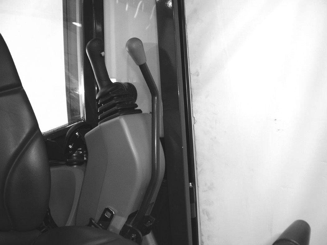
Figure 160
When the left console is raised [Figure 160], the hydraulic control levers (joysticks) and traction system must not function.
Sit in the operator's seat, fasten the seat belt and start the engine.
Raise the left console [Figure 160]
Move the joystick control levers. There should be no movement of the boom, arm, slew or bucket.
Move the steering control levers. There should be no movement of the excavator tracks.
Service the system if these controls do not deactivate when the left control console is raised. (See your Bobcat dealer for service.)
Inspection And Maintenance WARNING
Failure to properly inspect and maintain the seat belt can cause lack of operator restraint resulting in serious injury or death.
W-2466-0703
Check the seat belt daily for correct function.
Inspect the seat belt system thoroughly at least once each year or more often if the machine is exposed to severe environmental conditions or applications.
Any seat belt system that shows cuts, fraying, extreme or unusual wear, significant discolourations due to ultraviolet UV exposure, dusty / dirty conditions, abrasion to the seat belt webbing, or damage to the buckle, latch plate, retractor (if equipped), hardware or any other obvious problem should be replaced immediately.
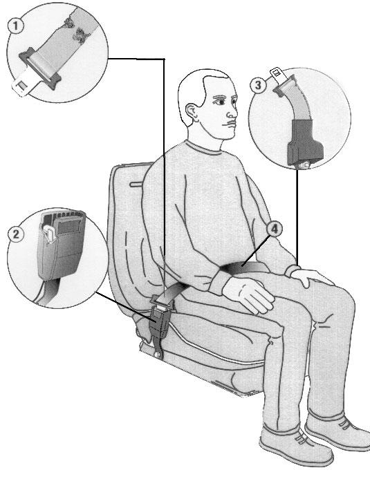
The items below are referenced in [Figure 161]
1.Check the webbing. If the system is equipped with a retractor, pull the webbing completely out and inspect the full length of the webbing. Look for cuts, wear, fraying, dirt and stiffness.
2.Check the buckle and latch for correct operation. Make sure latch plate is not excessively worn, deformed or buckle is not damaged or casing broken.
3.Check the retractor web storage device (if equipped) by extending webbing to determine if it looks correct and that it spools out and retracts webbing correctly.
4.Check webbing in areas exposed to ultraviolet (UV) rays from the sun or extreme dust or dirt. If the original colour of the webbing in these areas is extremely faded and / or the webbing is packed with dirt, the webbing strength can have deteriorated.
See your Bobcat dealer for seat belt system replacement parts for your machine.
MOTION ALARM SYSTEM Description
This excavator can be equipped with a motion alarm system. The motion alarm will sound when the operator moves the travel control levers in either the forward or reverse direction. Slight movement of the steering levers in either the forward or reverse direction is required with hydraulic components before the motion alarm will sound.
Warning
Avoid Injury Or Death
When an engine is running in an enclosed area, fresh air must be added to avoid concentration of exhaust fumes. If the engine is stationary, vent the exhaust outside. Exhaust fumes contain odorless, invisible gases which can kill without warning.
W-2050-0807
Sit in the operator’s seat and fasten the seat belt. Start the engine. (See PRE-STARTING PROCEDURE on Page 62.)
Move the travel control levers (one lever at a time) in the forward direction. The motion alarm must sound. Move the travel control levers (one lever at a time) in the reverse direction. The motion alarm must sound.
Return both levers to NEUTRAL and turn excavator key to OFF position. Exit the excavator. (See STOPPING THE ENGINE AND LEAVING THE EXCAVATOR on Page 69.)
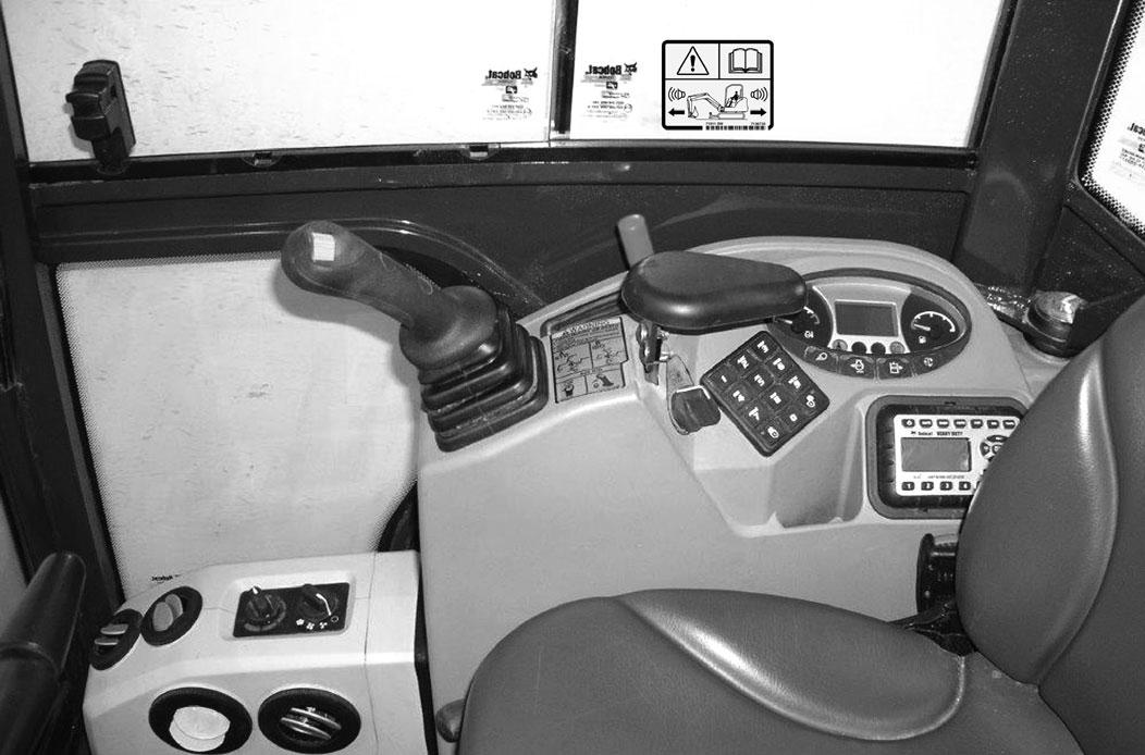
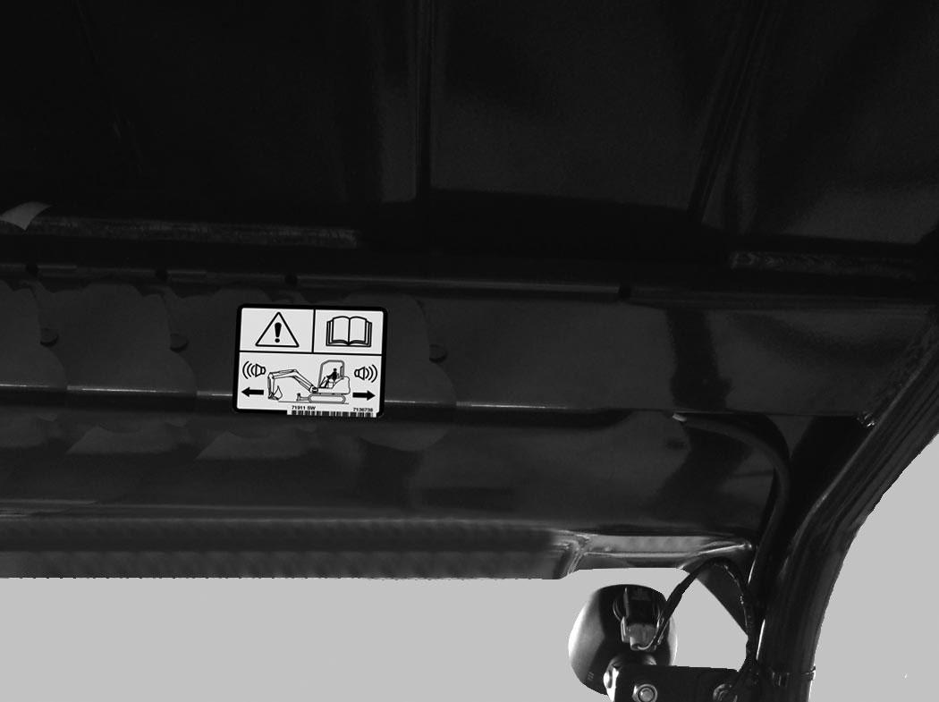
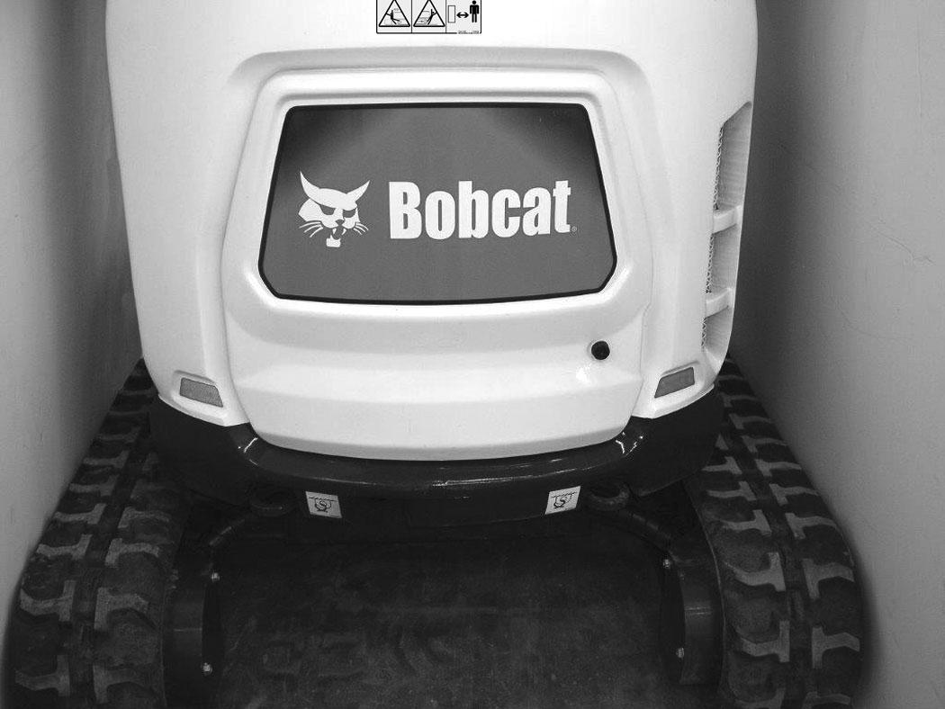
Inspect for damaged or missing motion alarm decal (Item 1) [Figure 162] (cab machine) or (Item 1) [Figure 163] (canopy machine). Replace if required.
NOTE:The excavator will need to be moved slightly in both the forward and reverse direction to test the motion alarm. Keep all bystanders away from machine during test.
MOTION ALARM SYSTEM (CONT’D)
Inspecting (Cont’d)
Adjusting Switch Position
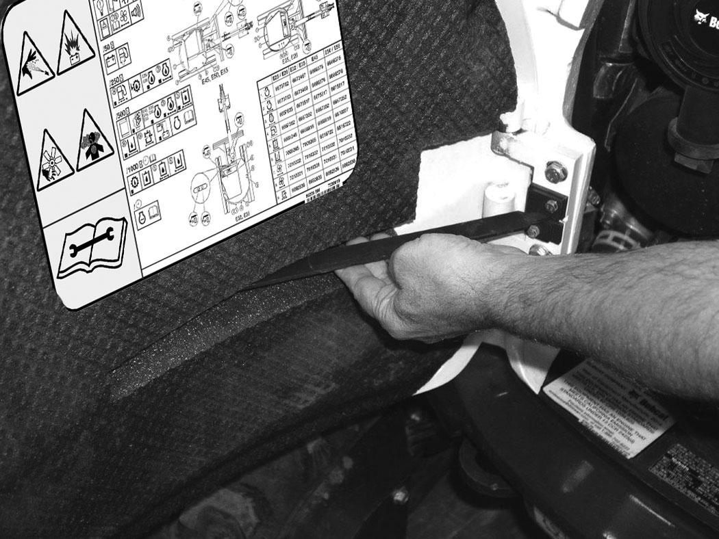
The two motion alarm switches are located in the two travel control sections of the control valve that is located under the floorplate. Remove the floor mat and the floorplate. (See the Service Manual for the correct procedure.)
Figure 165
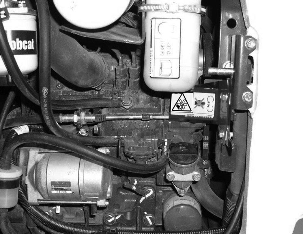
The motion alarm (Item 1) [Figure 164] is mounted to the bottom rear of the excavator. (Next to the engine oil pan.)
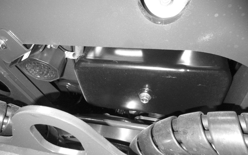
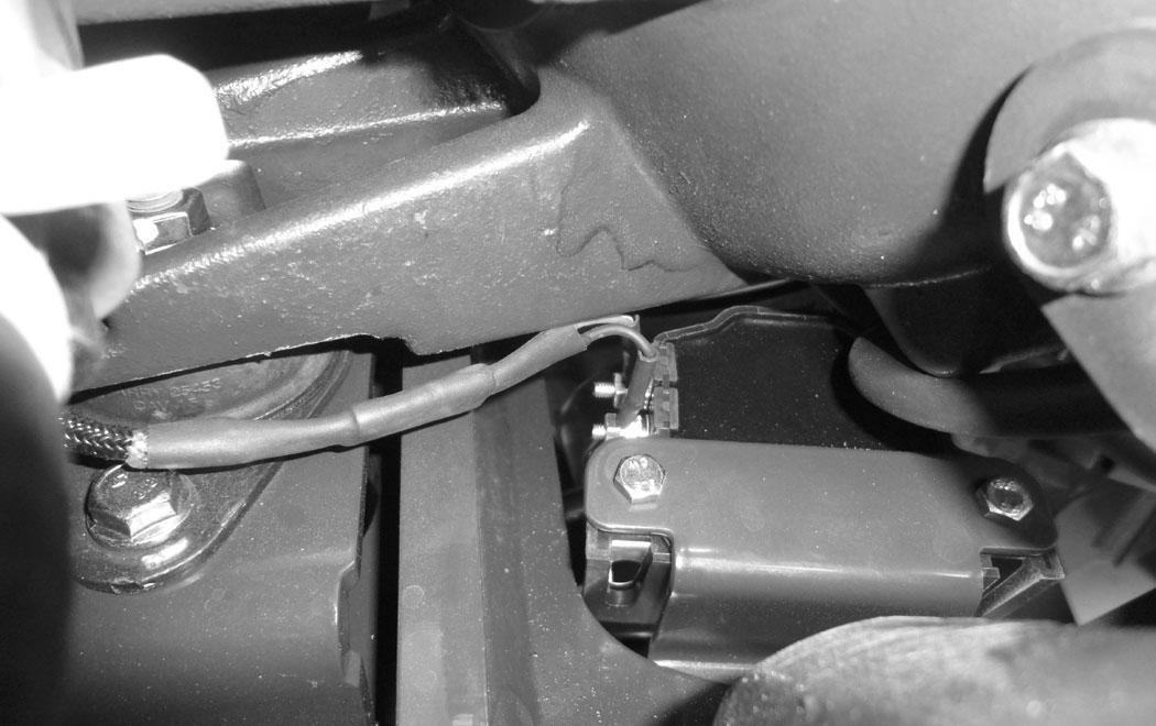
Inspect the motion alarm electrical connections (Item 2), wire harness (Item 3) [Figure 164] and motion alarm switch (Item 1) [Figure 165] for tightness and damage. Repair or replace any damaged components.
The motion alarm switch are non-adjustable, see the following information.
Warning
This machine is equipped with a motion alarm. ALARM MUST SOUND! when operating forward or backward.
Failure to maintain a clear view in the direction of travel could result in serious injury or death.
The operator is responsible for the safe operation of this machine.
W-2786-0309
The two switches are non-adjustable.
Inspect the motion alarm electrical connections (Item 1) [Figure 165] and wire harness for damage. Repair or replace any damaged components.
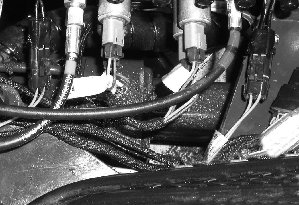
Inspect the motion alarm system for proper function after switch replacement.
Opening And Closing
Warning
Avoid Injury Or Death
Never service or adjust the machine when the engine is running unless instructed to do so in the manual.
W-2012-0497
Warning
Keep the rear door closed when operating the machine. Failure to do so could seriously injure a bystander.
To close the tailgate, lift up on the latch (Item 1) [Figure 167] and slowly start to close the tailgate. Push firmly to close the tailgate.
Adjusting The Latch
Press the button (Item 1) [Figure 166] and open the tailgate.
Open the tailgate and rotate outward until it is held open by the latch (Item 1) [Figure 167]
The tailgate latch (Item 1) can be adjusted by loosening the two bolts (Item 2) [Figure 168], moving the latch, and tightening the two bolts.
Close the tailgate before operating the excavator.
Right Side Cover
Opening And Closing
Right Side
169
Open the tailgate to access the right side cover latch (Item 1) [Figure 169]
Pull out the lever (Item 1) [Figure 169] and open the right side cover.
Cab Filters
Cleaning And Maintenance
Fresh Air Filter
The fresh air filter must be cleaned regularly. (See SERVICE SCHEDULE on Page 101.)
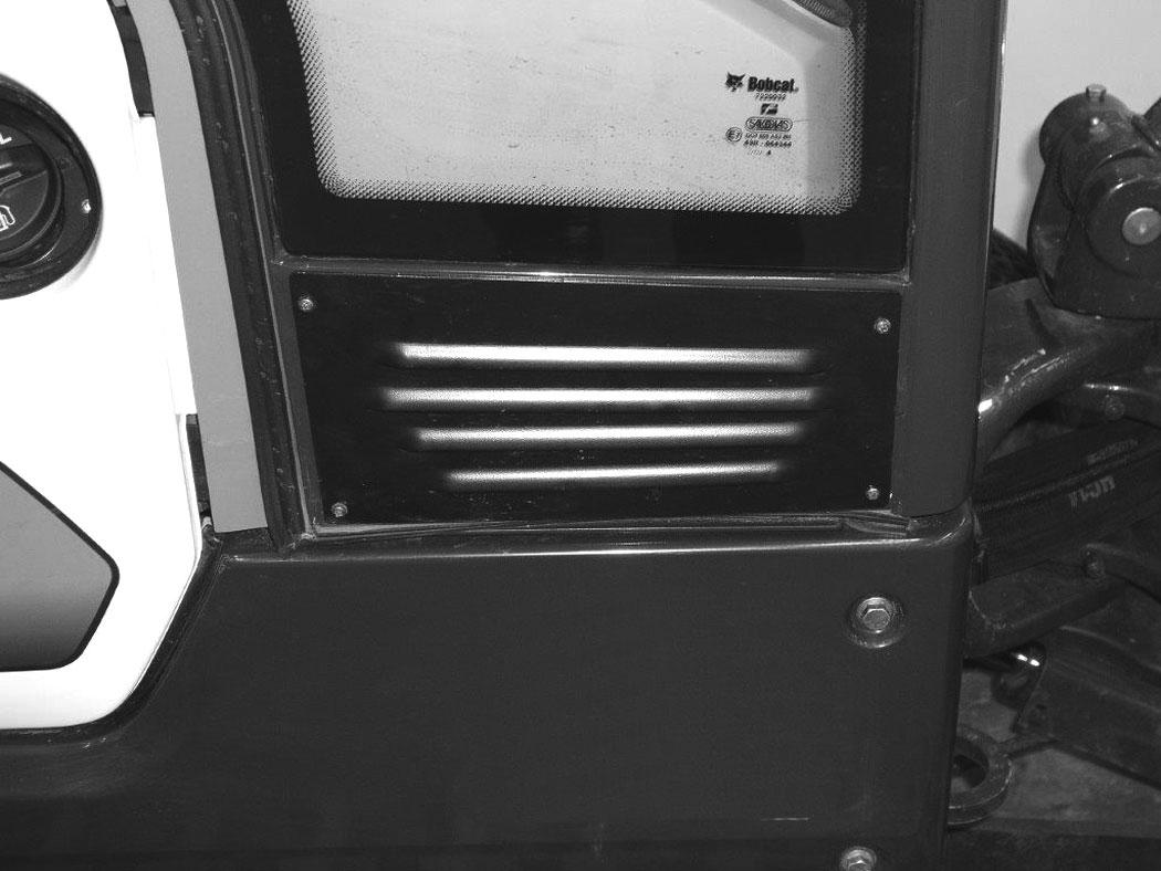
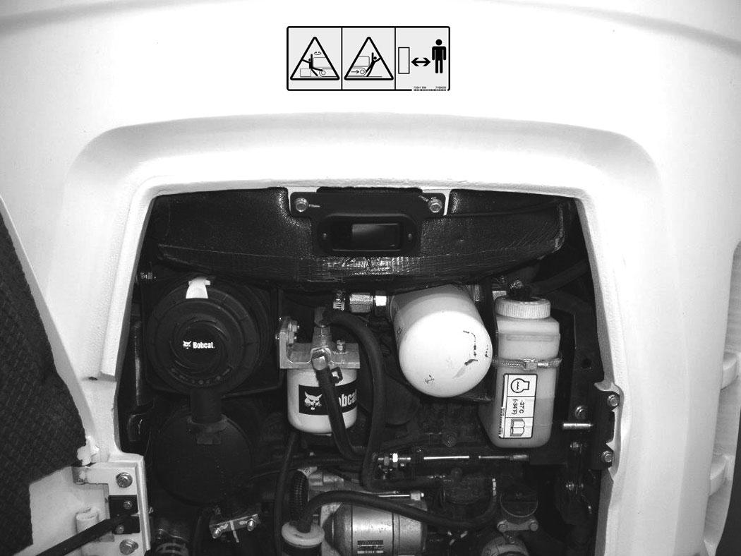
The fresh air filter is located on the right front corner of the cab.
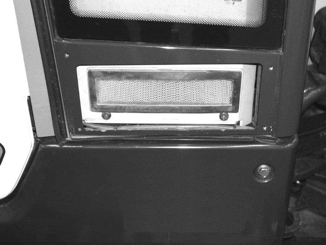
Open the right side cover and rotate forward until it is held open by the latch (Item 1) [Figure 170]
To close the tailgate, lift up on the latch (Item 1) [Figure 170] and slowly start to close the tailgate.
Pull the filter (Item 1) [Figure 172] out of the housing. Use low air pressure to clean the filter. Replace the filter when very dirty.
Reinstall the cover (Item 2) and the four screws (Item 1) [Figure 171]
Air Cleaner Service
See the service schedule for the correct service interval. (See SERVICE SCHEDULE on Page 101.)
Daily Check
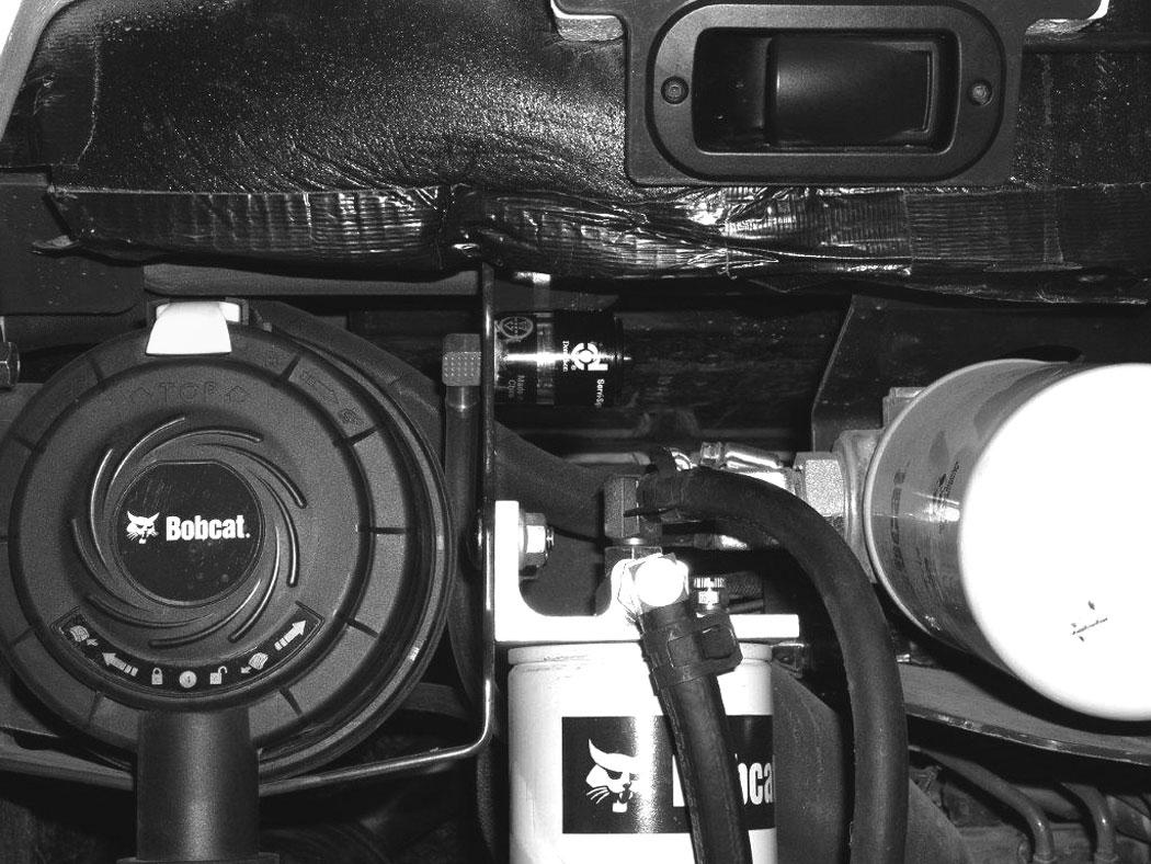
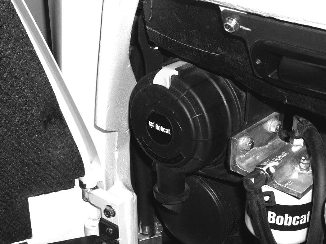
The air cleaner is located in the engine compartment. Open the tailgate to access the air cleaner for service. (See TAILGATE on Page 107.)
Check the condition indicator (Item 1) [Figure 173]. If the red ring shows in the condition indicator, the filter needs to be replaced.
Replace the inner filter every third time the outer filter is replaced or as indicated.
Replacing The Filter Elements
Slightly rotate the filter and pull the outer filter (Item 1) [Figure 175] from the air cleaner housing.
Check the housing for damage.
Clean the housing and the seal surface. DO NOT use compressed air.
Install a new filter.
Pull out on the latches (Item 1). Rotate the cover anticlockwise and remove the dust cover (Item 2) [Figure 174]

AIR CLEANER SERVICE (CONT’D)
Replacing The Filter Elements (Cont’d)
Position the dust cover (Item 1) [Figure 176] to the housing. Rotate the housing clockwise until the latch is at the top as shown.
Secure the dust cover (Item 1) and by pushing in on the latch (Item 2) [Figure 176].
Check the air intake hose and the air cleaner housing for damage. Make sure all connections are tight.
After the outer filter has been replaced, press the button (Item 2) [Figure 173] on the end of the condition indicator.
Start the engine. Run at full rpm, then reduce engine speed and stop the engine.
If the red ring (Item 1) [Figure 173] shows in the condition indicator, replace the inner filter.
Inner Filter
Only replace the inner filter under the following conditions:
•Replace the inner filter every third time the outer filter is replaced.
•After the outer filter has been replaced, press the button (Item 2) [Figure 173] on the condition indicator and start the engine. Run at full rpm, then reduce engine speed and stop the engine. If the red ring shows in the condition indicator, replace the inner filter.
Remove the dust cover, outer filter and inner filter (Item 1) [Figure 177].
NOTE:Make sure all sealing surfaces are free of dirt and debris.
Install the new inner filter.
Install the outer filter and the dust cover.
Press the button on the condition indicator to reset the red ring.