9 minute read
TRACK FRAME RETRACTION - EXPANSION Operation


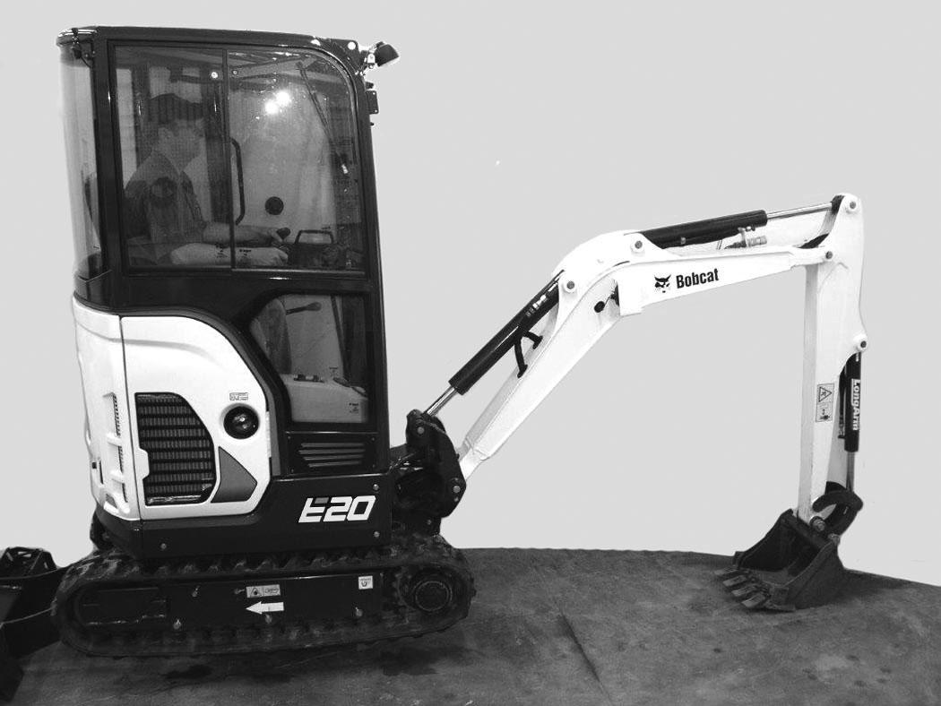
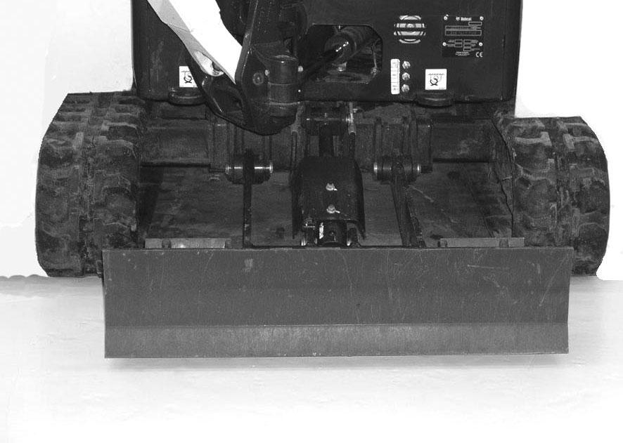
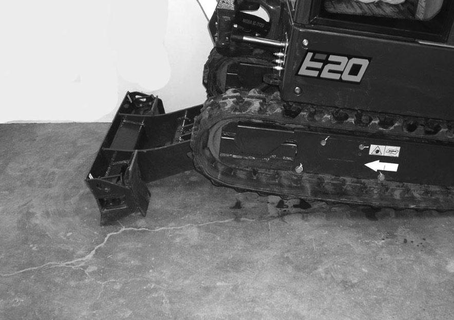
The excavator can be operated with the track frame retracted for transportation on a trailer or to access narrow areas [Figure 55]
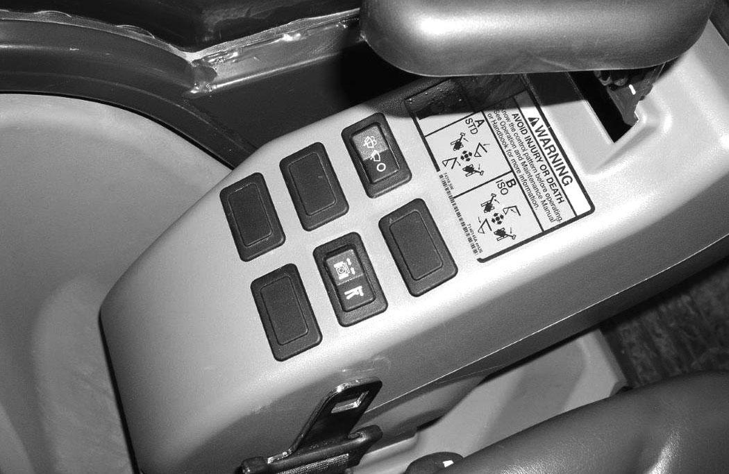
Put the Blade / Track Retraction - Expansion Switch (Item 1) [Figure 57] to the right in the Blade position.
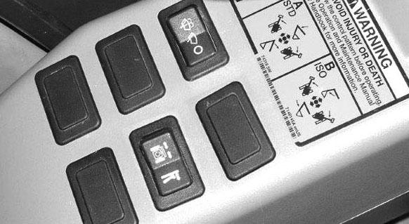
With the boom and arm positioned over the blade, lower the blade until the track is raised 100 – 150 mm (4.00 –6.00 in) off the ground [Figure 57]
Rotate the upperstructure 180 degrees.
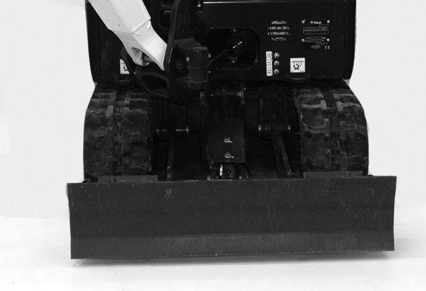
Expand the track frame for increased digging performance [Figure 56]
Important
To prevent wear and damage to the track, always lift the excavator before expanding or retracting the track frame.
I-2193-0599
Lower the boom and arm to raise the rear of the excavator until the track is 100 – 150 mm (4.00 – 6.00 in) off the ground [Figure 58]
TRACK FRAME RETRACTION - EXPANSION (CONT’D)
Operation (Cont’d)
Push the Blade / Track Retraction - Expansion Switch (Item 1) [Figure 59] to the Track Retraction - Expansion position.
Important
To prevent wear and damage to the track, always lift the excavator before expanding or retracting the track frame.
NOTE: Always return the Blade / Track RetractionExpansion Switch (Item 1) [Figure 61] to the Blade position during operation so that the track does not move when using the Blade / Track Retraction - Expansion Lever.
Raise the boom and arm to lower the rear of the excavator to the ground.
Rotate the upperstructure 180 degrees.
Raise the blade until the tracks are on the ground.
Blade Expansion
Figure 62
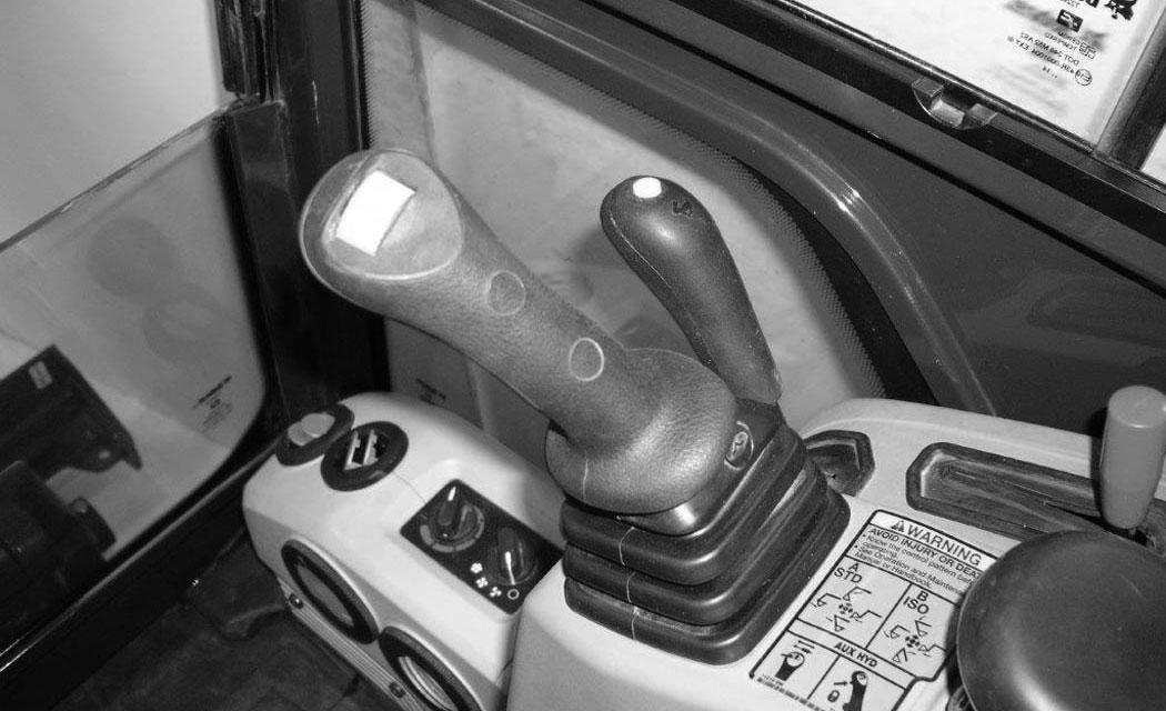
Push the Blade / Track Retraction - Expansion Lever (Item 1) [Figure 60] forward to expand the track frame. Hold the lever forward until the track frame is fully expanded.
Pull the Blade / Track Retraction - Expansion Lever [Figure 60] back to retract the track frame. Hold the lever back until the track frame is fully retracted.
The track frame must be either in the fully expanded or fully retracted position when in use.
Raise the blade sightly and place a block under the blade. Lower the blade fully.
Remove the blade retainer pin assembly (Item 1) [Figure 62]
Remove and reposition the blade extension (Item 2) [Figure 62] to the outside blade position.
Reinstall the blade retainer pin assembly (Item 3) [Figure 62]

NOTE:Always operate the machine with the tracks fully expanded or fully retracted.

BOOM SWING Operation
Depending on how the machine is configured, there are two different control options available for the boom swing controls.
1. Using the left joystick switch (Item 1) [Figure 63] or
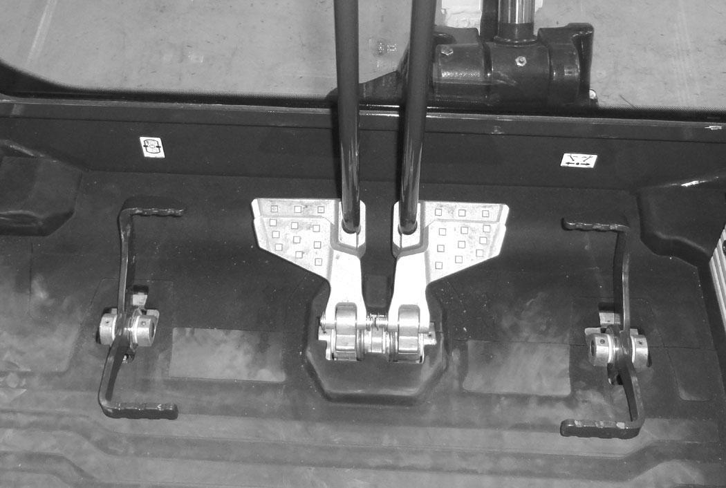
2. Using the right foot pedal (Item 2) [Figure 63]

Press Boom Swing / Second Auxiliary Hydraulic switch (Item 1) [Figure 63] (if equipped) to the left, boom swing position.
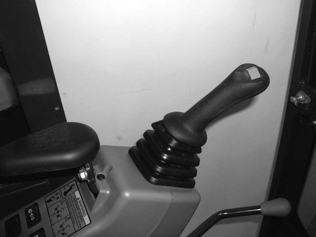
When equipped with Joystick Switch (Item 1) [Figure 64]:
The boom swing switch (Item 1) [Figure 64] (if equipped) on the left control lever (joystick) controls boom swing. Move the switch to the left to swing the boom to the left. Move the switch to the right to swing the boom to the right.
When equipped with Boom Swing Pedal (Item 2) [Figure 65]:
The boom swing pedal (Item 2) (if equipped) controls boom swing. Press the toe (Item 3) of the pedal to swing the boom to the right. Press the heel (Item 4) [Figure 65] of the pedal to swing the boom to the left.
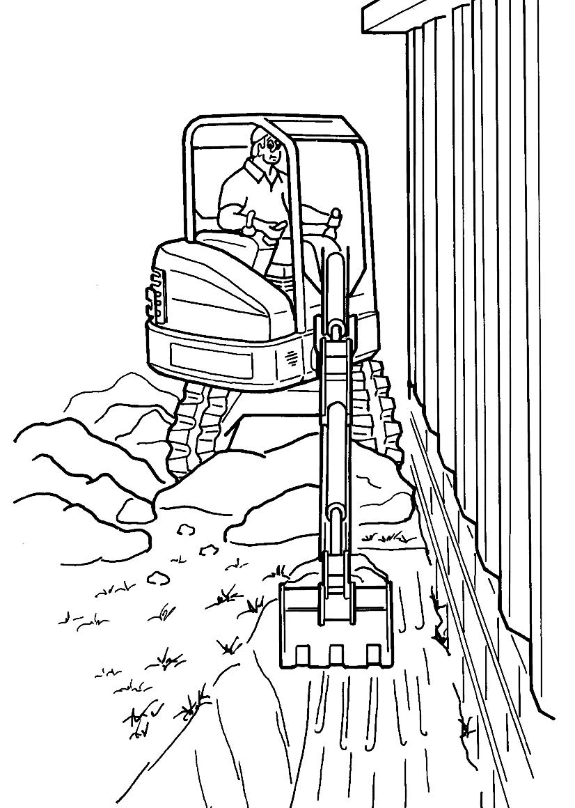
NOTE:The purpose of the boom swing is to offset the boom with respect to the upperstructure for digging close to a structure [Figure 66].
Boom Load Holding Valve
Description
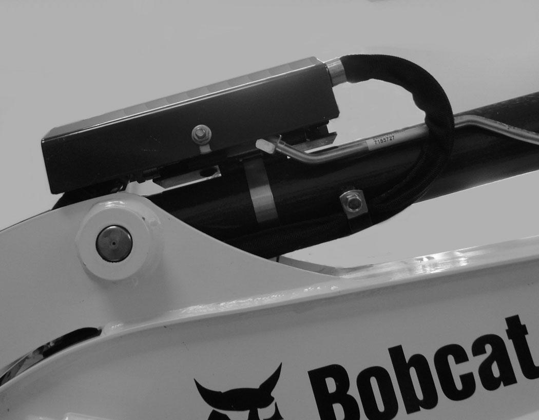
The boom load holding valve (if equipped) will hold the boom in its current position in the event of hydraulic pressure loss.
Warning
AVOID INJURY OR DEATH
Do Not work or stand under raised work equipment or attachment.
W-2793-0409
Lowering Boom With Load Holding Valve
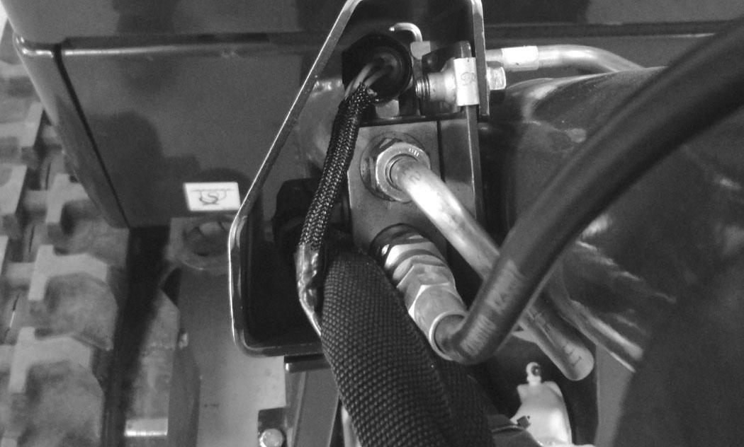
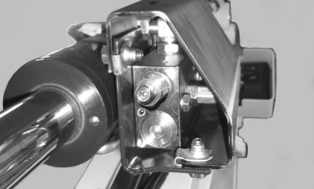
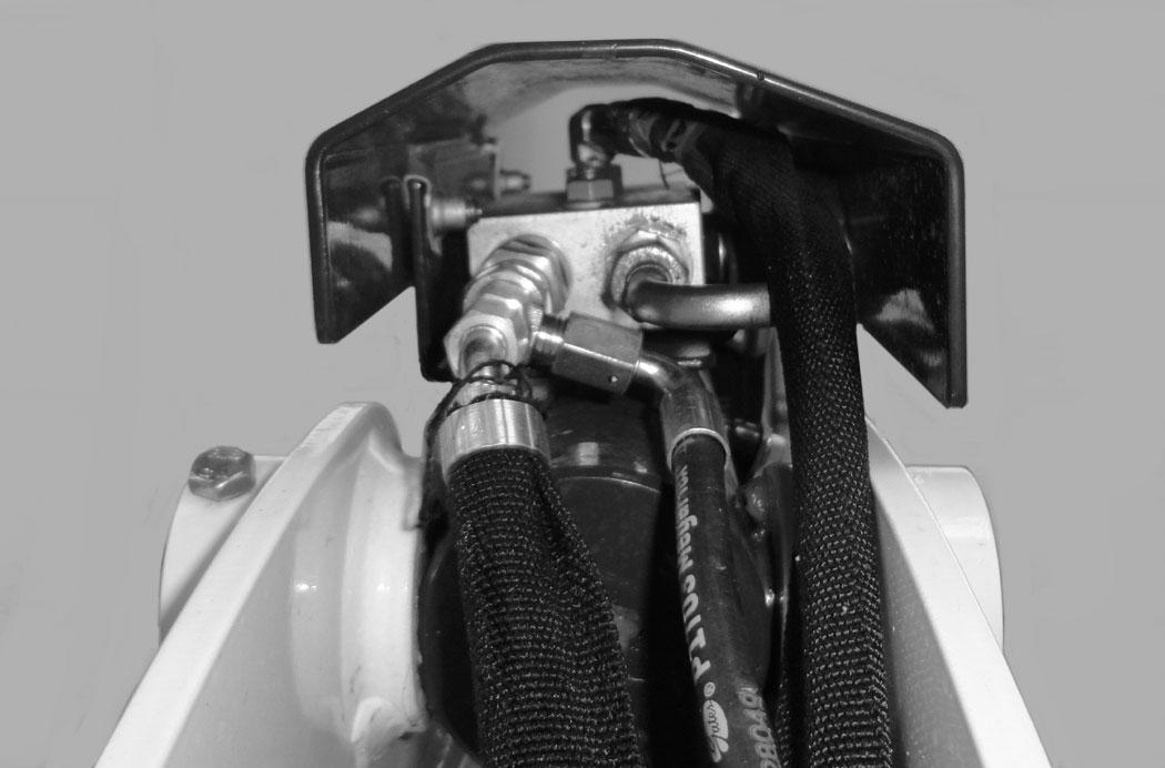
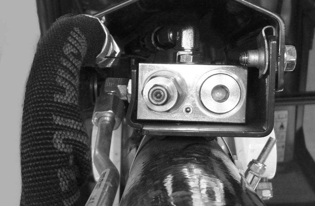
NOTE:DO NOT remove or adjust the port relief valve (Item 1) [Figure 68] (that the drain hose is connected to). If the port relief valve have been tampered with, see your Bobcat dealer for service.
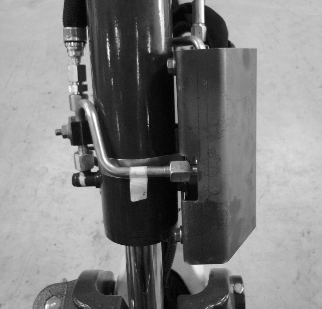
If the excavator is equipped with a boom load holding valve (Item 1) [Figure 67], it will be attached to the boom cylinder at the rod end.
NOTE:DO NOT remove or adjust the two port relief valves (Item 2) [Figure 67]. If the port relief valves have been tampered with, see your Bobcat dealer for service.

Warning
AVOID BURNS
Hydraulic fluid, tubes, fittings and quick couplers can get hot when running machine and attachments. Be careful when connecting and disconnecting quick couplers.
W-2220-0396
BOOM LOAD HOLDING VALVE (CONT’D)
Lowering Boom With Load Holding Valve (Cont’d)
Lowering procedures:
With base end hose failure, or with rod end hose failure and NO accumulator pressure:
NOTE:If the relief valve must me adjusted to lower the boom, the relief valve must be replaced. It can not be reset back to the factory setting.
Loosen the locknut (Item 1). Install a hex wrench into the valve screw (Item 2) [Figure 70] and slowly rotate the screw clockwise and allow the boom to lower to the ground.
Replace the relief valve [Figure 70]. See your Bobcat dealer for service parts.
With rod end hose failure - with accumulator pressure:
Place a container under the valve and hose end to contain hydraulic fluid. Enter the excavator and turn the key switch to the ON position or press the ENTER CODE Button (Keyless Panel), but do not start the engine. Slowly move the joystick boom lower function and allow the boom to lower to the ground.
Loss of hydraulic pressure:
Use the same procedure as: With base end hose failure, or with rod end hose failure and NO accumulator pressure.
ARM LOAD HOLDING VALVE
Description
The arm load holding valve (if equipped) will hold the arm in it’s current position in the event of hydraulic pressure loss.
Warning
AVOID INJURY OR DEATH
Do Not work or stand under raised work equipment or attachment.
W-2793-0409
NOTE:DO NOT remove or adjust the port relief valve (Item 1) [Figure 72] (that the drain hose is connected to). If the port relief valve have been tampered with, see your Bobcat dealer for service.
Warning
AVOID BURNS
Hydraulic fluid, tubes, fittings and quick couplers can get hot when running machine and attachments. Be careful when connecting and disconnecting quick couplers.
ARM LOAD HOLDING VALVE (CONT’D)
Lowering Arm With Load Holding Valve (Cont’d)
Lowering procedures:
With base end hose failure, or with rod end hose failure and NO accumulator pressure:
NOTE:If the relief valve must me adjusted to lower the boom, the relief valve must be replaced. It can not be reset back to the factory setting.
Loosen the locknut (Item 1). Install a hex wrench into the valve screw (Item 2) [Figure 74] and slowly rotate the screw clockwise and allow the arm to lower to the ground.
Replace the relief valve [Figure 74]. See your Bobcat dealer for service parts.
With rod end hose failure - with accumulator pressure:
Place a container under the valve and hose end to contain hydraulic fluid. Enter the excavator and turn the key switch to the ON position or press the ENTER CODE Button (Keyless Panel), but do not start the engine. Move the joystick arm retract function to slowly lower the arm.
Loss of hydraulic pressure:
Use the same procedure as: With base end hose failure, or with rod end hose failure and NO accumulator pressure
Overload Warning Device
Description
NOTE:The excavator must be equipped with the optional boom load holding valve to install the overload warning device.
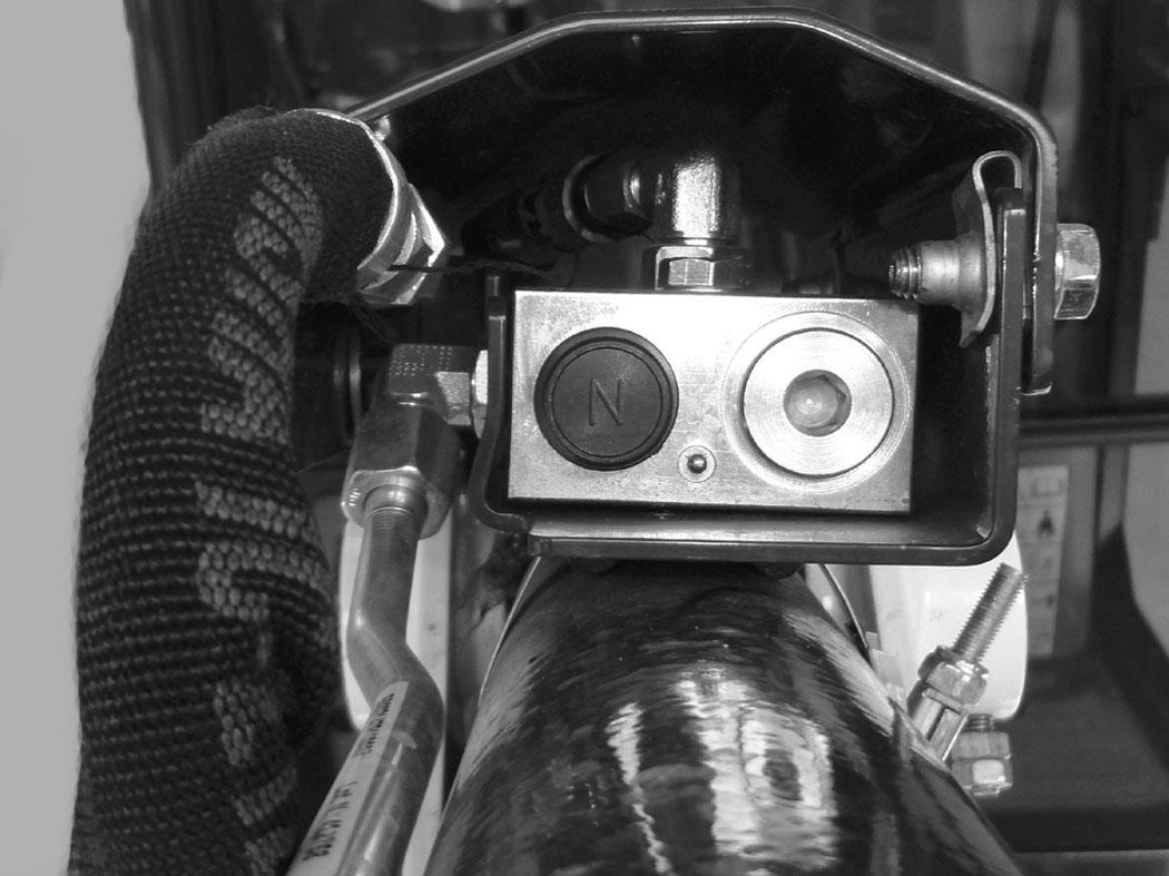
The overload warning device (if equipped) senses hydraulic pressure in the boom lift circuit. When the hydraulic pressure in the boom lift circuit reaches a predetermined pressure setting, a buzzer will sound that indicates an overload condition.
If the buzzer sounds, immediately move the arm closer to the excavator and lower the boom. Reduce the size of the load before attempting to re-lift the load.
Warning
AVOID INJURY OR DEATH
Do Not work or stand under raised work equipment or attachment.
W-2793-0409
Operation
Figure 75
Press the switch (Item 1) to the left. This will activate the optional pressure switch (Item 2) [Figure 75] in the boom load hold valve.

Press the switch (Item 1) [Figure 75] to the right to shut the overload warning feature OFF. P113531

DAILY INSPECTION
Daily Inspection And Maintenance
Maintenance work must be done at regular intervals. Failure to do so will result in excessive wear and early failures. The Service Schedule is a guide for correct maintenance of the Bobcat excavator.
Warning
AVOID INJURY OR DEATH
Instructions are necessary before operating or servicing machine. Read and understand the Operation & Maintenance Manual, Operator’s Handbook and signs (decals) on machine. Follow warnings and instructions in the manuals when making repairs, adjustments or servicing. Check for correct function after adjustments, repairs or service. Untrained operators and failure to follow instructions can cause injury or death.
W-2003-0807
Important
This machine is factory equipped with a spark arrester exhaust system.
A complete list of scheduled maintenance is also located in the Service Schedule (See SERVICE SCHEDULE on Page 101.)
Warning
Operator must have instructions before operating the machine. Untrained operators can cause injury or death.
W-2001-0502
NOTE:Fluids such as engine oil, hydraulic fluid, coolant, etc. must be disposed of in an environmentally safe manner. Some regulations require that certain spills and leaks on the ground must be cleaned in a specific manner. See local, state and federal regulations for correct disposal.
The spark arrester muffler, if equipped, must be cleaned to keep it in working condition. The spark arrester muffler must be serviced by dumping the spark chamber every 100 hours of operation.
On some models, the turbocharger functions as the spark arrester and must operate correctly for proper spark arrester function.
If this machine is operated on flammable forest, brush, or grass covered land, a spark arrester attached to the exhaust system may be required and must be maintained in working order. Refer to local laws and regulations for spark arrester requirements.
I-2284-EN-0909
DAILY INSPECTION (CONT’D)
Daily Inspection and Maintenance (Cont’d)
Check the following items before each day of operation:
•Operator Canopy or Cab (ROPS / TOPS) and mounting hardware.
•Check seat belt and mounting hardware. Replace seat belt if damaged.
•Check for damaged decals, replace as needed.
•Check control console lockout.
•Check Attachment Mounting System (if equipped) for damaged or loose parts.
•Check air cleaner and intake hoses / clamps.
•Check engine oil level and engine for leaks.
•Drain water from fuel filter.
•Check engine coolant level (in both the coolant recovery tank and in the radiator) and system for leaks.
•Check engine area for flammable materials.
•Check hydraulic fluid level and system for leaks.
•Check indicator lights for correct operation.
•Grease all pivot points.
•Check cylinder and attachment pivot points.
•Check the track tension.
•Repair broken and loose parts.
•Clean cab heater filter (if equipped).
•Check front horn and motion alarm (if equipped) for proper function.
Warning
Avoid Injury Or Death
•Keep door / cover closed except for service.
•Keep engine clean of flammable material.
•Keep body, loose objects and clothing away from electrical contacts, moving parts, hot parts and exhaust.
•Do not use the machine in space with explosive dusts or gases or with flammable material near exhaust.
•Never use ether or starting fluid on diesel engine with glow plugs or air intake heater. Use only starting aids as approved by engine manufacturer.
•Leaking fluids under pressure can enter skin and cause serious injury.
•Battery acid causes severe burns; wear goggles. If acid contacts eyes, skin, or clothing, flush with water. For contact with eyes, flush and get medical attention.
•Battery makes flammable and explosive gas. Keep arcs, sparks, flames and lighted tobacco away.
•For jump start, connect negative cable to the machine engine last (never at the battery). After jump start, remove negative connection at the engine first.
•Exhaust gases can kill. Always ventilate.
Important
Pressure Washing Decals
W-2782-0409
•Never direct the stream at a low angle toward the decal that could damage the decal causing it to peel from the surface.
•Direct the stream at a 90 degree angle and at least 300 mm (12 in) from the decal. Wash from the center of the decal toward the edges.
I-2226-0910
PRE-STARTING PROCEDURE
Operation & Maintenance Manual And Operator’s Handbook Locations
77
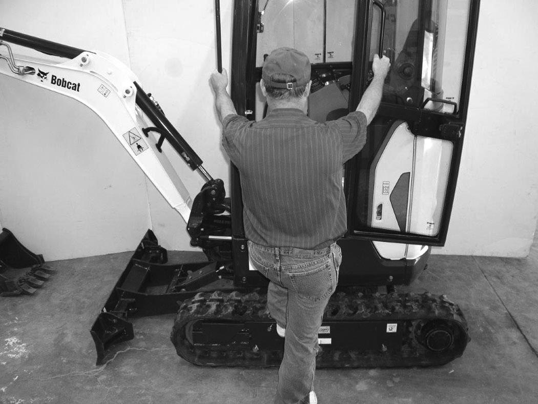
Entering The Excavator
Warning
AVOID INJURY OR DEATH
Instructions are necessary before operating or servicing machine. Read and understand the Operation & Maintenance Manual and signs (decals) on machine. Follow warnings and instructions in the manuals when making repairs, adjustments or servicing. Check for correct function after adjustments, repairs or service. Untrained operators and failure to follow instructions can cause injury or death.
W-2003-EN-0614
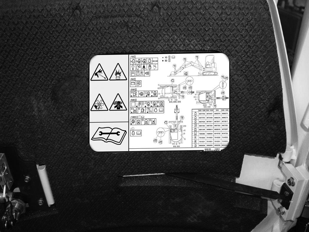
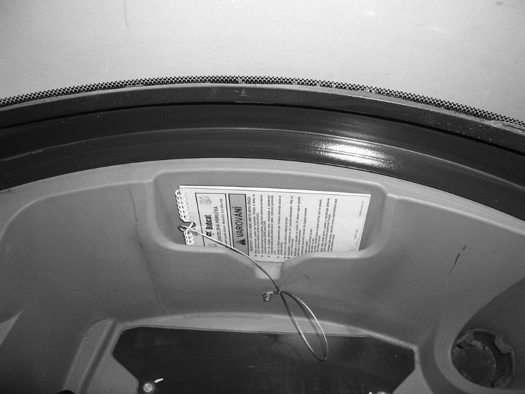
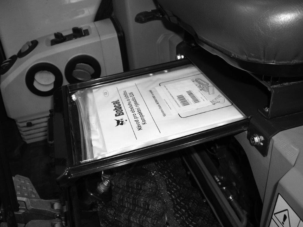
Read and understand the Operation & Maintenance Manual (Item 1) [Figure 77] (located inside the storage box below the operator’s seat) and the Operator’s Handbook (Item 1) [Figure 78] located behind the operator’s seat before operating.
PRE-STARTING PROCEDURE (CONT’D)
Seat Adjustment
Basic Seat (If Equipped)
Figure 80
The basic seat has no adjustments [Figure 80]
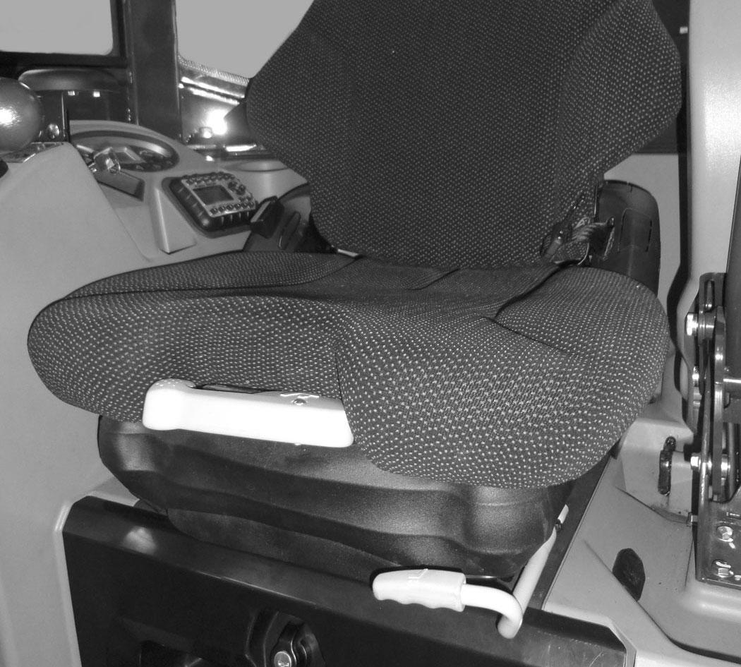
Standard Seat (If Equipped)
Figure 81
Release the seat lever (Item 1) [Figure 81] to adjust the seat forward or back.
Release the seat lever (Item 2) [Figure 81] to adjust the position of the back cushion.
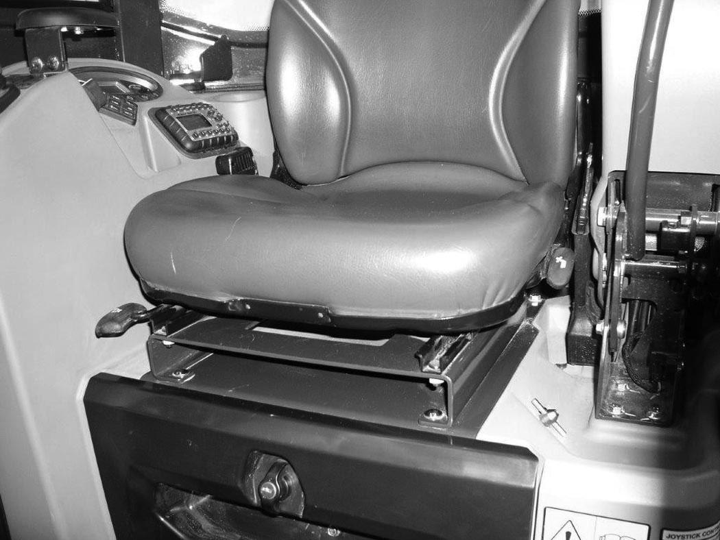
Suspension Seat (If Equipped)

Figure 82
Release the seat lever (Item 1) [Figure 82] to adjust the seat forward or back.

Turn the handle (Item 2) [Figure 82] to change the adjustment for operator weight.
Release the lever (Item 3) [Figure 82] to change the incline of the seat back.
Seat Belt
Figure 83
Fasten the seat belt [Figure 83]