18 minute read
MONITORING THE DISPLAY PANELS


Instrument Panel
Figure 92
Frequently monitor the temperature and fuel gauges [Figure 92]
After the engine is running, frequently monitor the instrument panel [Figure 92] for machine condition.
The associated icon is displayed if there is an error condition.
EXAMPLE: Engine Coolant Temperature is High.
The Engine Coolant Temperature icon (Item 1) [Figure 92] is ON.
Press the Information button (Item 2) [Figure 92] repeatedly to cycle the data display until the service code screen is displayed. One of the following SERVICE CODES is displayed.
• [M0810] Engine Coolant Temperature Too High
• [M0811] Engine Coolant Temperature Extremely High
Find the cause of the service code and correct before operating the excavator again. (See DIAGNOSTIC SERVICE CODES on Page 142.)
Warning And Shutdown
When a WARNING condition exists; the associated icon light is ON and the alarm sounds 3 beeps. If this condition is allowed to continue, there may be damage to the engine or hydraulic systems.
When a SHUTDOWN condition exists; the associated icon light is ON and the alarm sounds continuously. The monitoring system will automatically stop the engine in 15 seconds. The engine can be restarted to move or relocate the excavator.
The SHUTDOWN feature is associated with the following icons:
General Warning
Engine Malfunction
Engine Coolant Temperature
STOPPING THE ENGINE AND LEAVING THE EXCAVATOR
Procedure
Figure 93
Expand the tracks fully. Stop the machine on level ground. Lower the work equipment and the blade to the ground [Figure 93].
Turn the switch to STOP [Figure 95]
Disconnect the seat belt. Remove the key from the switch (if equipped) to prevent operation of machine by unauthorised personnel. Raise the control console and exit the machine.


Move the engine speed control lever (Item 1) [Figure 94] back to low idle.
Run the engine at idle speed for about 5 minutes to allow it to cool.
Attachments
Installing And Removing The Attachment (Pin-On Attachment)
Installation
Warning
AVOID INJURY OR DEATH
Stop the machine on a firm flat surface. When removing or installing attachments (such as a bucket), always have a second person in the operator’s seat, give clear signals and work carefully.
W-2140-0189
Install
Removal
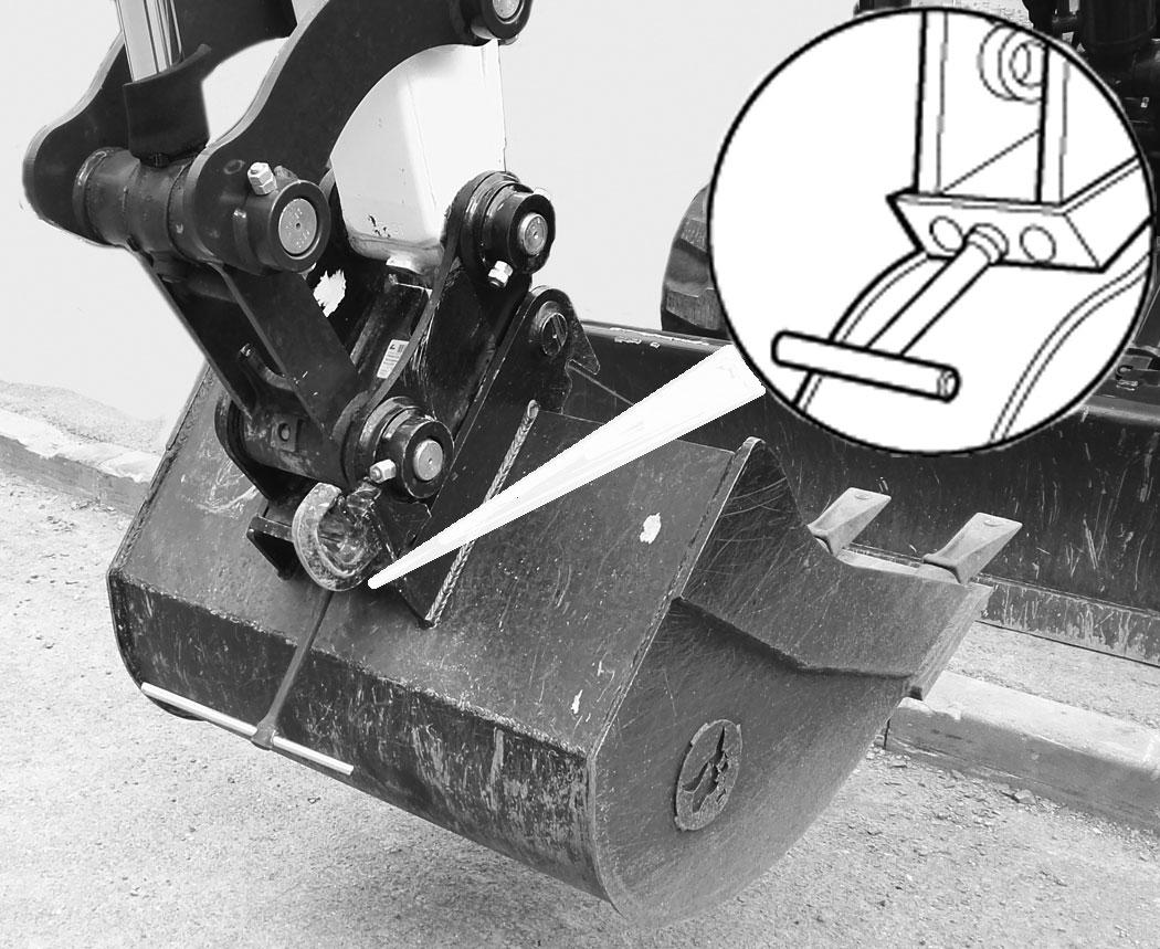
Park the excavator on a flat surface and lower the bucket fully.
Remove the two retainer pins (Item 1) [Figure 97]
Remove the washers and pins (Items 1 and 3) [Figure 96].
Do not damage the dust seals in the arm.
Install the arm into the bucket and align the mounting hole.
Install the pin (Item 1) [Figure 96] and washers.
Install the link (Item 2) in the bucket and align the mounting hole. Install the pin (Item 3) [Figure 96] and washers

Warning
AVOID INJURY OR DEATH
Never use attachments or buckets which are not approved by Bobcat Company. Buckets and attachments for safe loads of specified densities are approved for each model. Unapproved attachments can cause injury or death.
W-2052-0907
ATTACHMENTS (CONT’D)

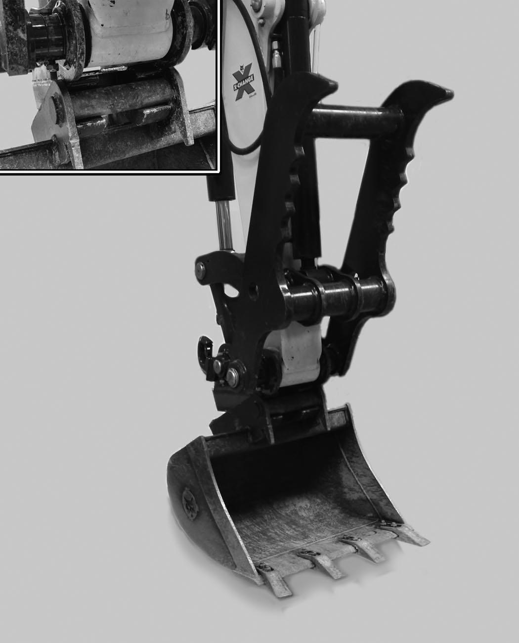
Installing And Removing The Attachment (Quick Coupler, Klac™ System)
Installation
NOTE: Installation and removal of the bucket is shown. The procedure is the same for other attachments. Disconnect any hydraulic lines that are operated by hydraulic power before removing any attachments (breaker, auger etc.).
Warning
AVOID INJURY OR DEATH
Never use attachments or buckets which are not approved by Bobcat Company. Buckets and attachments for safe loads of specified densities are approved for each model. Unapproved attachments can cause injury or death.
W-2052-0907
NOTE:Coupler equipped with the lifting device can only be used on machines where the overload warning device and the boom and arm load holding valves are installed. See your Bobcat dealer for available kits.
Warning
AVOID INJURY
Keep fingers and hands out of pinch points when latching and unlatching the attachment quick coupler.
W-2541-1106
Fully retract the bucket cylinder.
Stop the engine and exit the excavator.
Inspect the quick coupler to make sure the latch is in the unlatched position (Item 1) [Figure 98].

If in the latched position, see [Figure 99] for additional information.
If the latch is in the unlatched position, proceed to [Figure 100]
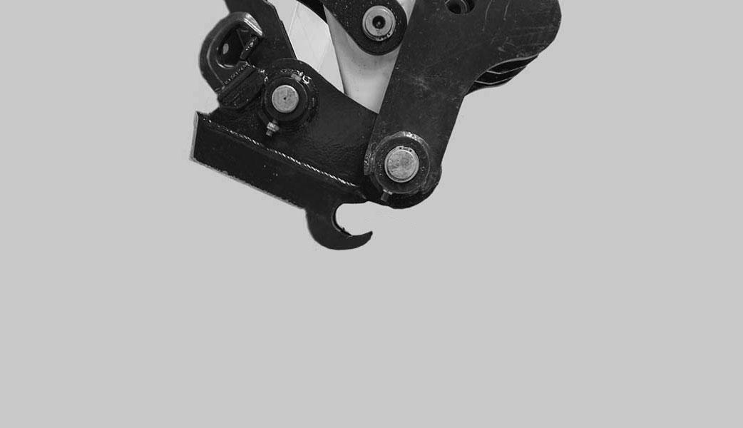
To unlatch the quick coupler, install the tool (Item 1) [Figure 99] and pull the handle. The latch will move completely forward. The latch will lock in the unlatched position.
Enter the excavator, fasten the seat belt and start the engine.
Position the quick coupler (Item 1) to the attachment (Item 2) [Figure 100]
ATTACHMENTS (CONT’D)
Installing And Removing The Attachment (Quick Coupler, Klac™ System) (Cont’d)
Installation (Cont’d)
There must be at least 100° between the quick coupler surface (Item 1) and the attachment mounting surface (Item 2) [Figure 101]. Extend the arm out to get the required angle for proper installation.
NOTE: There must be proper clearance (100° minimum) between the hook (Item 3) and the quick coupler (Item 4) [Figure 101]. Possible damage to the attachment hooks or the quick coupler could occur without proper clearance.
Raise the boom until there is approximately 500 mm (20.0 in) of clearance between the bottom of the attachment and the ground [Figure 103]
Raise the boom and extend the arm until the hooks of the attachment (Item 1) engage the pins (Item 2) of the quick coupler [Figure 102]
Extend the bucket cylinder (Item 1) [Figure
Lower the attachment until it is flat on the ground.
Engage the parking brake.
Stop the engine and exit the excavator.
ATTACHMENTS (CONT’D)
Installing And Removing The Attachment (Quick Coupler, Klac™ System) (Cont’d)
Installation (Cont’d)
Visually inspect the quick coupler latch (Item 1) to the bucket mount (Item 2) [Figure 105]. The latch must be fully engaged.
Warning
Avoid Injury
Keep fingers and hands out of pinch points when latching and unlatching the attachment quick coupler.
W-2541-1106
If the latch is not engaged, install the tool (Item 1) in the hole (Item 2) [Figure 106] of the quick coupler and push down to unlatch the quick coupler. Remove the tool. Enter the excavator, fasten the seat belt and start the engine. Raise the attachment 500 mm (20 in) off of the ground and fully extend the bucket cylinder. Lower the attachment until it is flat on the ground. Engage the parking brake. Stop the engine and exit the excavator.
Again, visually inspect the quick coupler to make sure the latch (Item 1) [Figure 105] is fully engaged. If it is not fully engaged, remove the attachment and inspect both the quick coupler and the attachment for damage or debris. (See [Figure 121] for Quick Coupler And Attachment Inspection information.)


ATTACHMENTS (CONT’D)
Installing And Removing The Attachment (Quick Coupler, Klac™ System) (Cont’d)
AVOID INJURY
Keep fingers and hands out of pinch points when latching and unlatching the attachment quick coupler.
W-2541-1106
Position the attachment flat on the ground.
Install the quick coupler tool (Item 1) into the hole (Item 2) [Figure 106] in the quick coupler.
Push down on the tool (Item 1) [Figure 107] to unlock the latch.
Remove the tool.
Enter the excavator, fasten the seat belt and start the engine.
Retract the bucket cylinder fully and lower the boom [Figure 108] until the attachment is on the ground.
Continue to lower the boom and move the arm towards the excavator until the quick coupler is clear of the attachment [Figure 109].

ATTACHMENTS (CONT’D)
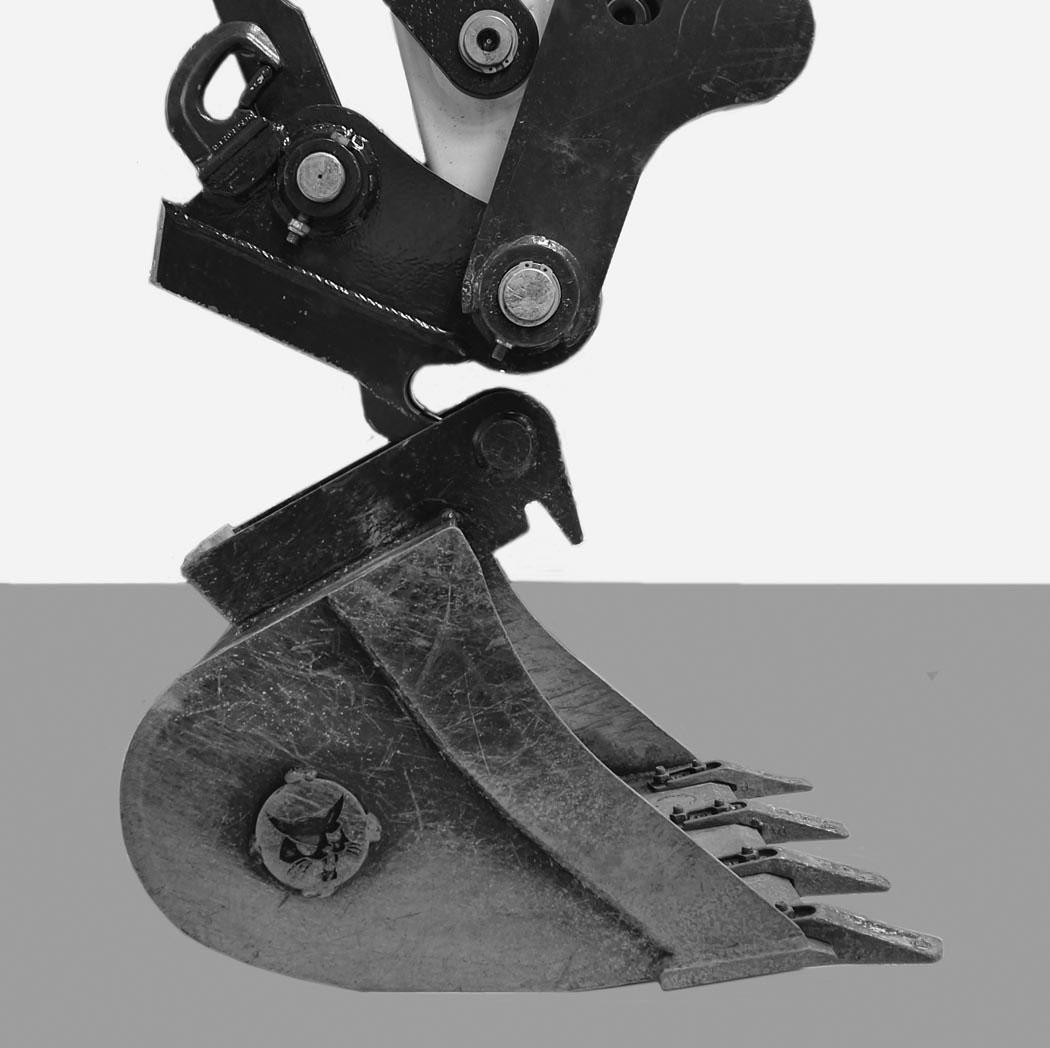
Installing And Removing The Attachment (Mechanical Pin Grabber Coupler)
Installation
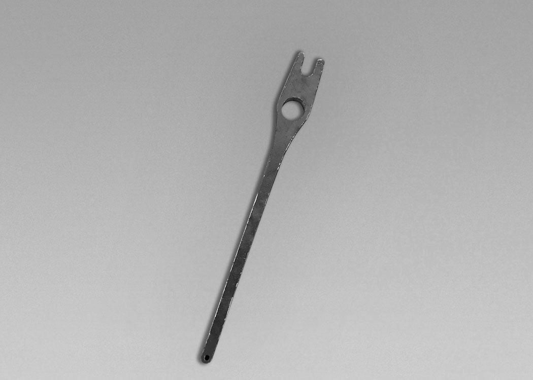
Figure 110
You have been supplied with the release tool [Figure 110] that is required to disengage and engage the safety lock. Do not use alternative tools, as they may damage the coupler.
Installation of the bucket is shown. The procedure is the same for other attachments. Disconnect any hydraulic lines that are operated by hydraulic power before removing any attachments (breaker, auger, etc.).
Warning
AVOID INJURY OR DEATH
Never use attachments or buckets which are not approved by Bobcat Company. Buckets and attachments for safe loads of specified densities are approved for each model. Unapproved attachments can cause injury or death.
W-2052-0907
Warning
Keep all bystanders 6 m (20 ft) away from equipment when operating. Contact with moving parts, a trench cave-in or flying objects can cause injury or death.
W-2119-0910
A coupler equipped with the lifting device can only be used on machines on which the overload warning device and boom and arm load holding valves are installed. See your Bobcat dealer for available kits.
If your machine is equipped with a hydraulic clamp, fully retract the hydraulic clamp cylinder so the clamp is out of the way for installing the attachment.
Figure 111
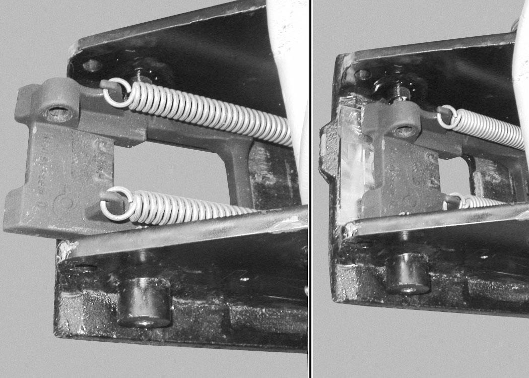
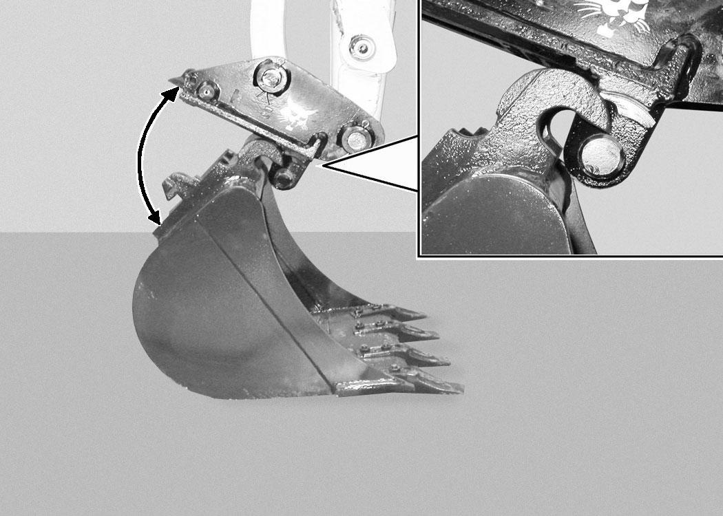
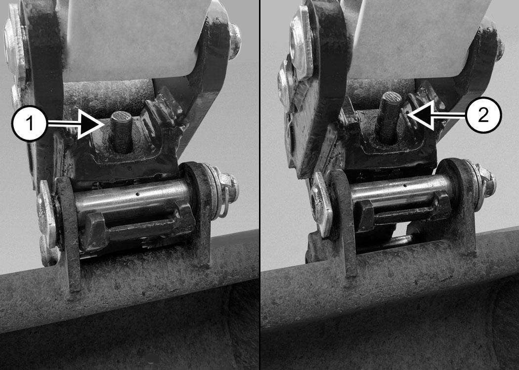
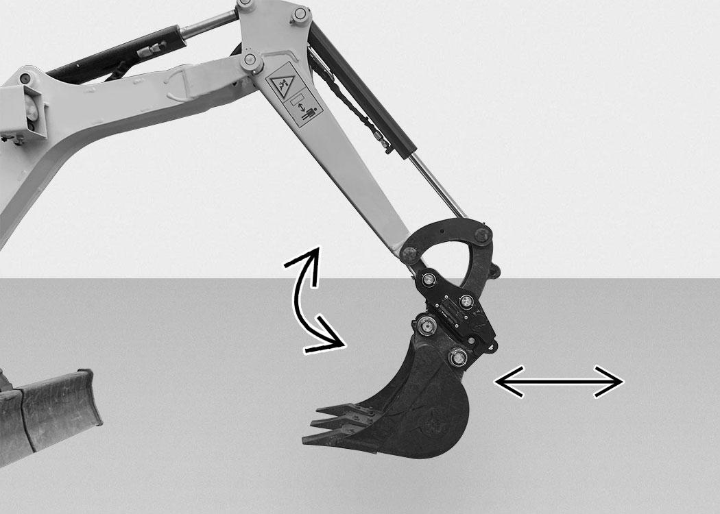
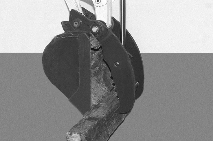
Inspect the quick coupler. If the wedge and the trigger are in the primed position (Item 1) [Figure 111] proceed to [Figure 113]
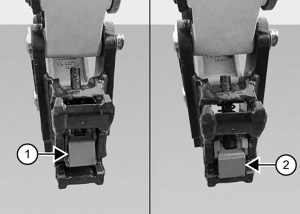
If the wedge is in the engaged position (Item 2) [Figure 111], proceed to [Figure 112]
Warning
AVOID INJURY
Keep fingers and hands out of pinch points when latching and unlatching the attachment quick coupler.
W-2541-1106
ATTACHMENTS (CONT’D)
Installing And Removing The Attachment (Mechanical Pin Grabber Coupler) (Cont’d)
Raise the boom until there is approximately 500 mm (20 in) of clearance between the bottom of the attachment and the ground.
To prepare the quick coupler, do the following:
1.Stop the engine and exit the excavator.
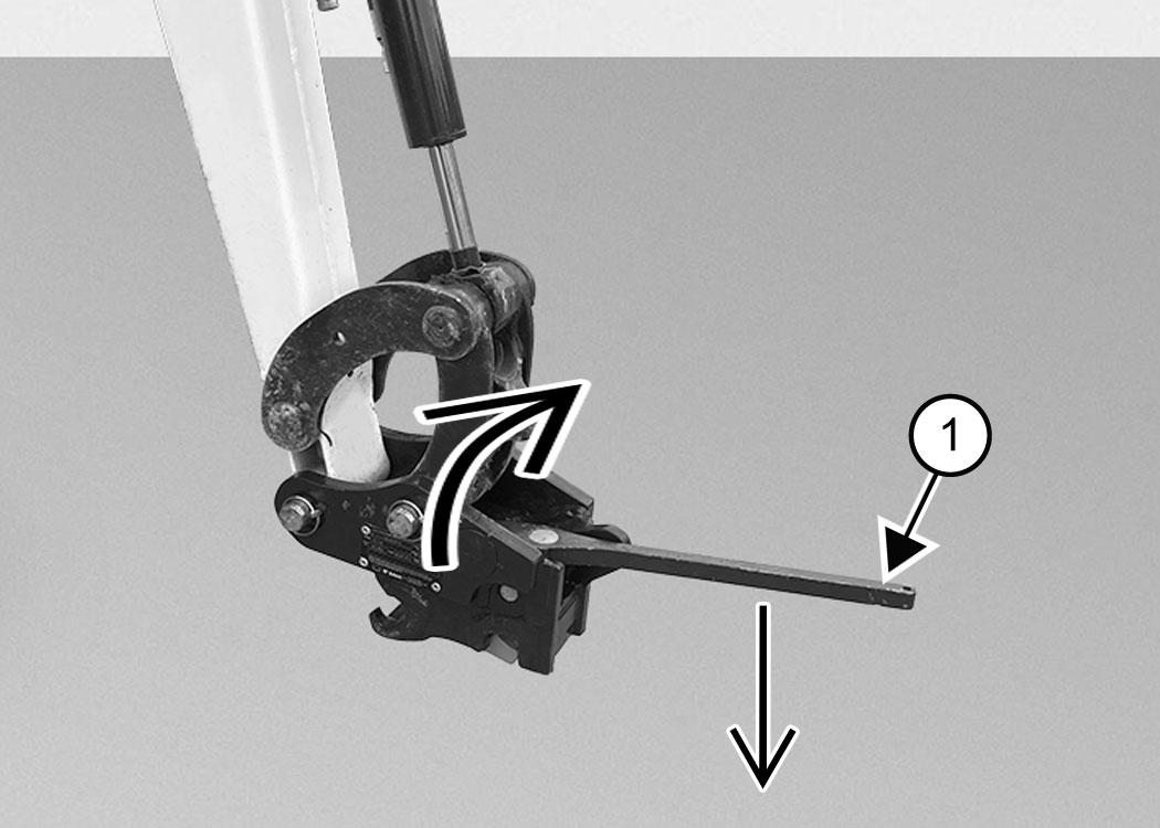
2.Install the release tool (Item 1) [Figure 112]
3.Rotate the release tool clockwise and hold [Figure 112]

4.Push the release tool down [Figure 112].
5.The bottom part of the wedge will withdraw from the rear pin slot and the trigger will drop down.
6.Remove the release tool and return it to a secure position.
7.Enter the excavator, fasten the seat belt, and start the engine.
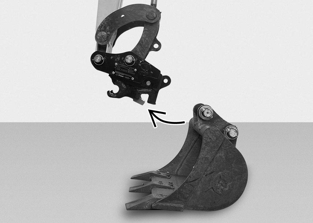
Extend the bucket cylinder and curl in the bucket [Figure 114] until you hear the wedge engage on the attachment back pin.
Guide the coupler front hooks onto the attachment front pin [Figure 113]
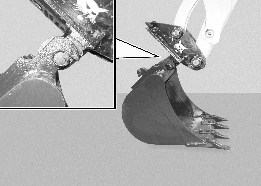
Visually inspect the indication bar to see if the coupler is fully engaged (Item 1) [Figure 115]
If the visual indicator bar is not fully engaged (Item 2) [Figure 115], the attachment must not be operated. Turn off the excavator and examine the coupler for dirt build up or damage. Refer to the service manual for further information.
ATTACHMENTS (CONT’D)
Installing And Removing The Attachment (Mechanical Pin Grabber Coupler) (Cont’d)
Warning
AVOID INJURY OR DEATH
The quick coupler locking clasps / pins must be fully engaged and locked to the attachment pins. Failure to fully engage the locking clasps / pins can allow attachment to come off.

W-3024-0417
Removal
Removal of the bucket is shown. The procedure is the same for other attachments. Disconnect any hydraulic lines that are operated by hydraulic power before removing any attachments (breaker, auger, etc.).
Warning
AVOID INJURY OR DEATH
Never use attachments or buckets which are not approved by Bobcat Company. Buckets and attachments for safe loads of specified densities are approved for each model. Unapproved attachments can cause injury or death.
W-2052-0907
Warning
Keep all bystanders 6 m (20 ft) away from equipment when operating. Contact with moving parts, a trench cave-in or flying objects can cause injury or death.
W-2119-0910
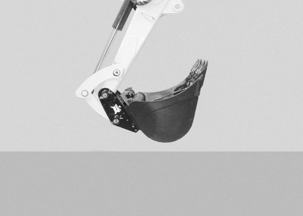
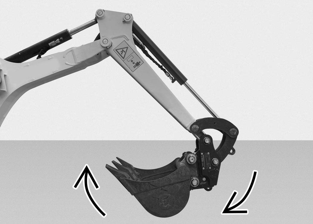
Shake the attachment vigorously and / or carry out a bump test to ensure the attachment is secured to the coupler [Figure 116]
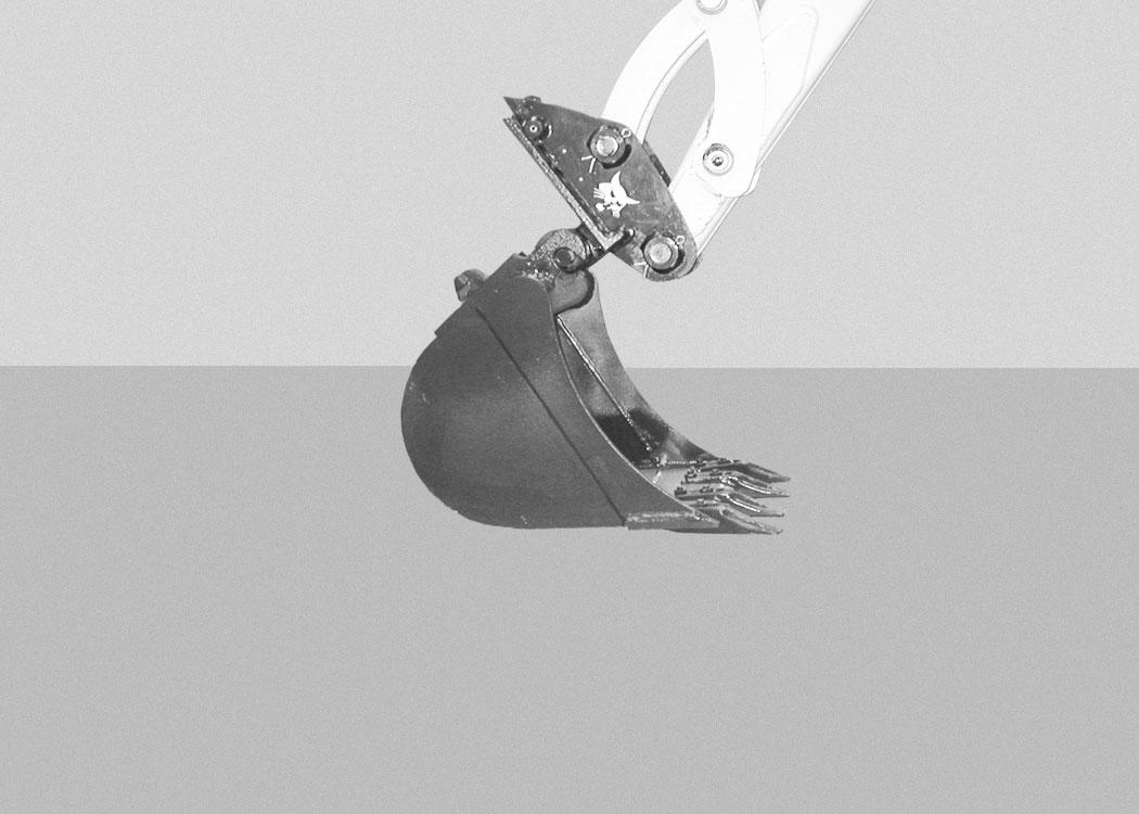
Position the attachment close to ground level at the angle shown [Figure 117]
The bucket / attachment pins should be approximately parallel to the ground.
ATTACHMENTS (CONT’D)
Installing And Removing The Attachment (Mechanical Pin Grabber Coupler) (Cont’d)
Warning
AVOID INJURY
Keep fingers and hands out of pinch points when latching and unlatching the attachment quick coupler.
W-2541-1106
Rotate the release tool clockwise and hold [Figure 119]
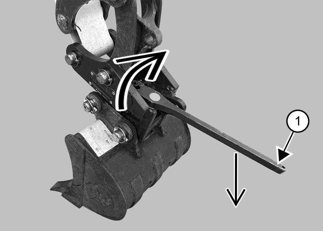
Press the release tool down against the wedge to disengage the attachment back pin [Figure 119].
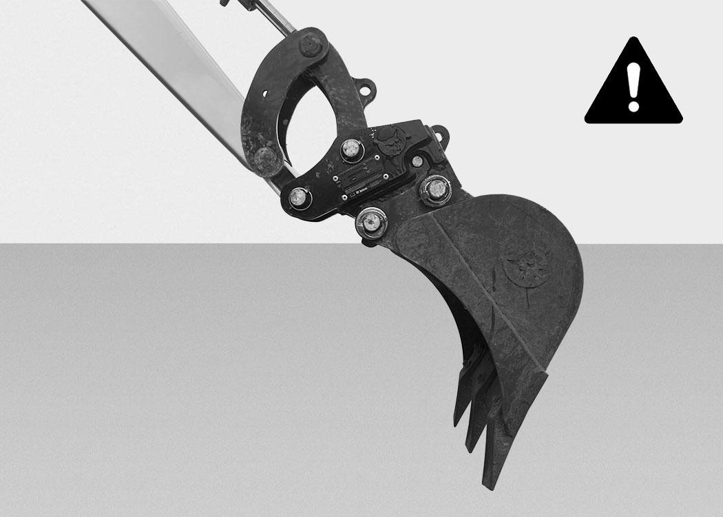
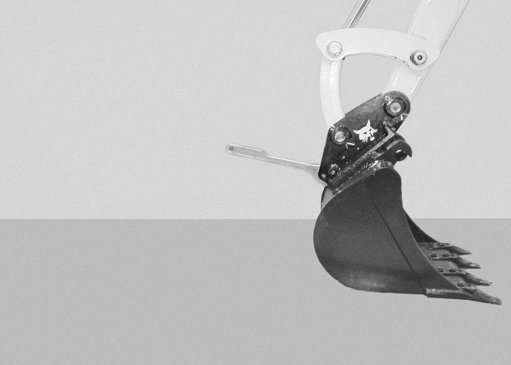
DO NOT RELEASE AN ATTACHMENT WITH THE COUPLER CURLED OPEN [Figure 118].
Stop the engine and exit the excavator.
Warning
AVOID INJURY
Keep fingers and hands out of pinch points when latching and unlatching the attachment quick coupler.
W-2541-1106
Remove the release tool and return it to a secure position.
Enter the excavator, fasten the seat belt, and start the engine.
Lower the attachment to the ground.
Roll the coupler back until the coupler disengages from the attachment.
Figure 120
Firmly insert the release tool (Item 1) [Figure 119]
Move the arm away from the attachment [Figure 120].
ATTACHMENTS (CONT’D)
Quick Coupler And Attachment Inspection
P-72274 2
ATTACHMENTS (CONT’D)
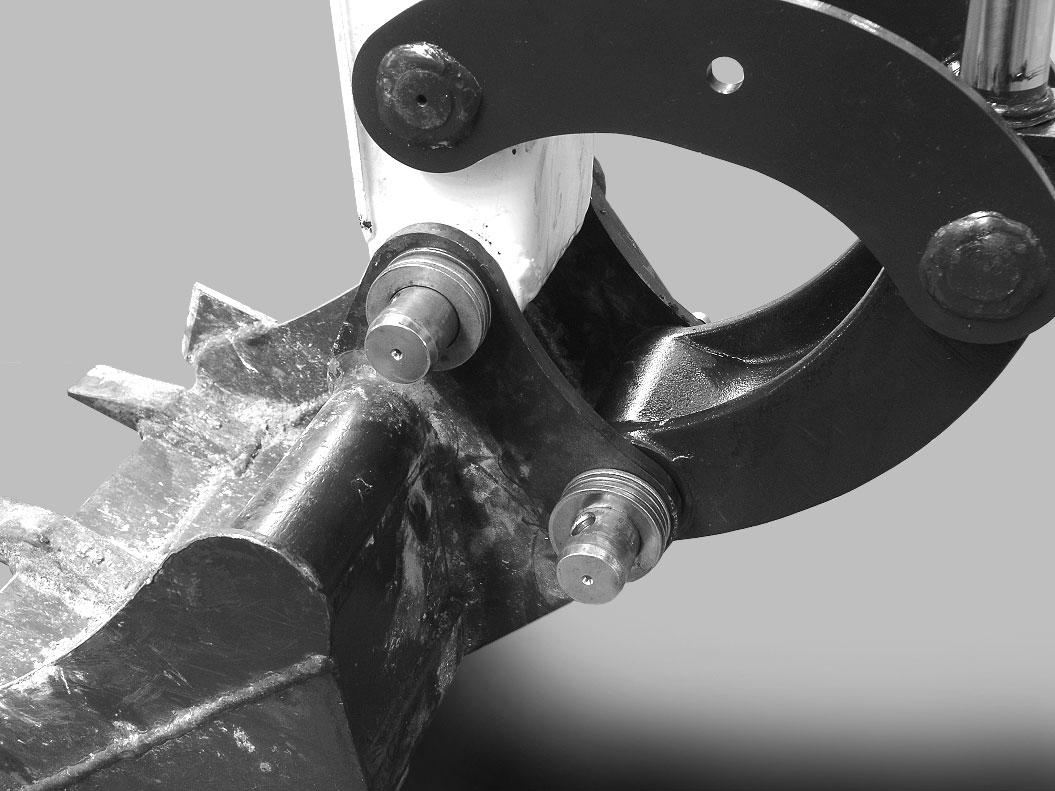
Installing And Removing The Attachment (German Style Coupler)
The type of quick coupler installed on the excavator may influence the excavator’s rated lift capacity and the availability of attachments.

To determine the lift capacity changes, (See Lift Capacity on Page 87.)
For the rated lift capacity charts, (See Rated Lift Capacity - With Standard Arm And Canopy (No Demolition Kit) on Page 152.), (See Rated Lift Capacity - With Standard Arm And Canopy (With Demolition Kit) on Page 153.), (See Rated Lift Capacity - With Standard Arm And Cab (No Demolition Kit) on Page 154.), (See Rated Lift Capacity - With Standard Arm And Cab (With Demolition Kit) on Page 155.), (See Rated Lift Capacity - With Long Arm And Canopy (No Demolition Kit) on Page 156.), (See Rated Lift Capacity - With Long Arm And Canopy (With Demolition Kit) on Page 157.), (See Rated Lift Capacity - With Long Arm And Cab (No Demolition Kit) on Page 158.), (See Rated Lift Capacity - With Long Arm And Cab (With Demolition Kit) on Page 159.)
See you Bobcat dealer for a list of approved attachments for the type of quick coupler installed on the machine.
NOTE:Coupler equipped with the lifting device can only be used on machines where the overload warning device and the boom and arm load holding valves are installed. See your Bobcat dealer for available kits.
Installation
NOTE: Installation and removal of the bucket is shown. The procedure is the same for other attachments. Disconnect any hydraulic lines that are operated by hydraulic power before removing any attachments (breaker, auger etc.).
NOTE:If equipped with a hydraulic clamp, fully retract the hydraulic clamp cylinder so the clamp is out of the way for installing the attachment.
Avoid Injury Or Death
Never use attachments or buckets which are not approved by Bobcat Company. Buckets and attachments for safe loads of specified densities are approved for each model. Unapproved attachments can cause injury or death.
W-2052-0907
ATTACHMENTS (CONT’D)
Installing And Removing The Attachment (German Style Coupler) (Cont’d)

Installation (Cont’d)

ATTACHMENTS (CONT’D)
Installing And Removing The Attachment (German Style Coupler) (Cont’d)
Installation (Cont’d)
Stop the engine and leave the machine. (See STOPPING THE ENGINE AND LEAVING THE EXCAVATOR on Page 69.)
Use the supplied wrench (Item 1) [Figure 127] and turn the wrench clockwise until the locking pins fully engaged.
Warning
Avoid Injury Or Death
The quick coupler locking pins must be fully engaged and locked to the attachment pins. Failure to fully engage the locking pins can allow attachment to come off.
W-3023-0417
Visually check that the locking pins (Item 1) [Figure 128] are extended through the holes in the attachment mounting frame, securely fastening the attachment to the coupler.
If both locking pins do not engage in the locked position, see your Bobcat dealer for service.
Warning
Keep all bystanders 6 m (20 ft) away from equipment when operating. Contact with moving parts, a trench cave-in or flying objects can cause injury or death.
W-2119-0910
Enter the excavator, fasten the seat belt and start the engine. (See STARTING THE ENGINE on Page 65.)
With the attachment as low to the ground as possible, curl the attachment out and in several times to ensure the attachment is secured to the coupler.
Lower the attachment flat to the ground.
Park the excavator on a level surface.
ATTACHMENTS (CONT’D)
Installing And Removing The Attachment (German Style Coupler) (Cont’d)
Removal
Enter the excavator, fasten the seat belt and start the engine. (See PRE-STARTING PROCEDURE on Page 62.)
Figure 129
Raise the boom.
Move the right joystick (Item 1) [Figure 123] to the left (IN) and curl the coupler (Item 1) [Figure 129] toward the cab fully.
Stop the engine and exit the excavator. (See STOPPING THE ENGINE AND LEAVING THE EXCAVATOR on Page 69.)
Enter the excavator, fasten the seat belt and start the engine. (See PRE-STARTING PROCEDURE on Page 62.)
With the attachment slightly off of the ground, roll the quick coupler back until the coupler starts to disengage from the attachment [Figure 131]


Use the supplied wrench (Item 1) [Figure 130] and turn the wrench anticlockwise until the locking pins are fully disengaged.
Roll the quick coupler back fully and lower the boom and arm until the attachment is on the ground and the quick coupler is disengaged from the attachment pins [Figure 132]
Move the arm away from the attachment.
ATTACHMENTS (CONT’D)
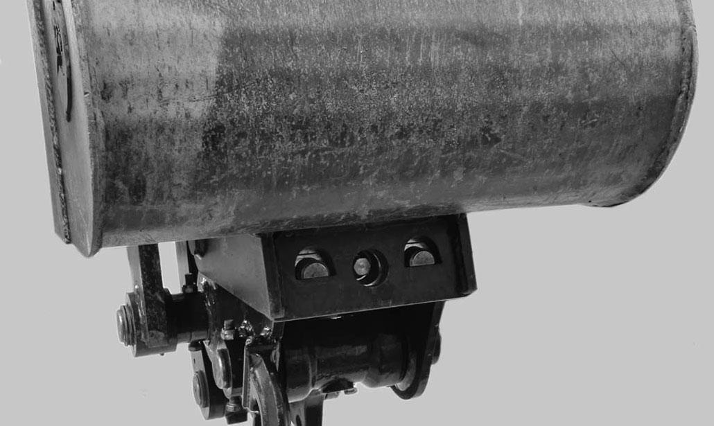
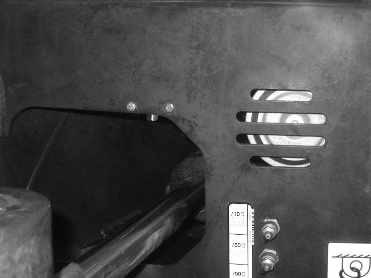
Identifying The Flail Mower Direct To Tank Valve
If your machine has a valve installed on the front of the machine above the boom swing cylinder as shown here (Item 1) [Figure 133], this indicates that the Flail Mower Direct To Tank Kit has been installed.
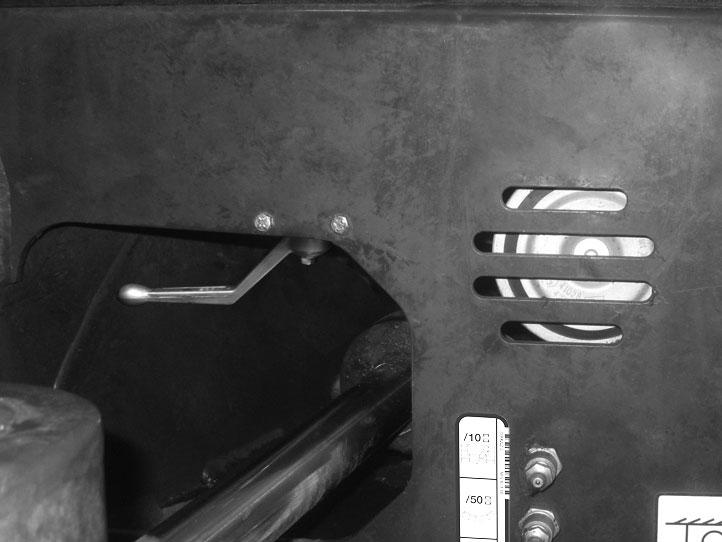
To operate the Direct To Tank system:
This kit is necessary for operating the Flail Mower attachment and is also suitable for the Breaker attachment to reduce back pressure, but not required. See Kit 7362790, Instruction 7362785.
1.Install a valve tool on the valve.
2.Rotate the valve stem 90° to the left to turn on direct to tank flow (Item 1) [Figure 134]
3.Rotate the valve stem 90° to the right to turn off direct to tank flow.
4.Remove valve tool and store.
NOTE: Do not leave the valve tool installed after use. Leaving the tool installed will interfere with cylinder operation and damage the valve.
OPERATING PROCEDURE Inspect The Work Area
Before beginning operation, inspect the work area for unsafe conditions.
Look for sharp drop-offs or rough terrain. Have underground utility lines (gas, water, sewer, irrigation, etc.) located and marked. Work slowly in areas of underground utilities.
Remove objects or other construction material that could damage the excavator or cause personal injury.
Always check ground conditions before starting your work:
•Inspect for signs of instability such as cracks or settlement.
•Be aware of weather conditions that can affect ground stability.
•Check for adequate traction if working on a slope.
Basic Operating Instructions
When operating on a public road or motorway, always follow local regulations. For example: A slow moving vehicle (SMV) sign, or direction signals can be required.
Run the engine at low idle speed to warm the engine and hydraulic system before operating the excavator.
Important
Machines warmed up with moderate engine speed and light load have longer life.
I-2015-0284
New operators must operate the excavator in an open area without bystanders. Operate the controls until the excavator can be handled at an efficient and safe rate for all conditions of the work area.
Operating Near An Edge Or Water
Keep the excavator as far back from the edge as possible and the excavator tracks perpendicular to the edge so that if part of the edge collapses, the excavator can be moved back.
Always move the excavator back at any indication the edge may be unstable.
Lowering The Work Equipment (Engine STOPPED)
The hydraulic control levers control the movement of the boom, arm, bucket and upperstructure slew functions.
The console must be in the locked down position, and the key switch in the ON position.
Use the control lever to lower the boom.
Figure 135
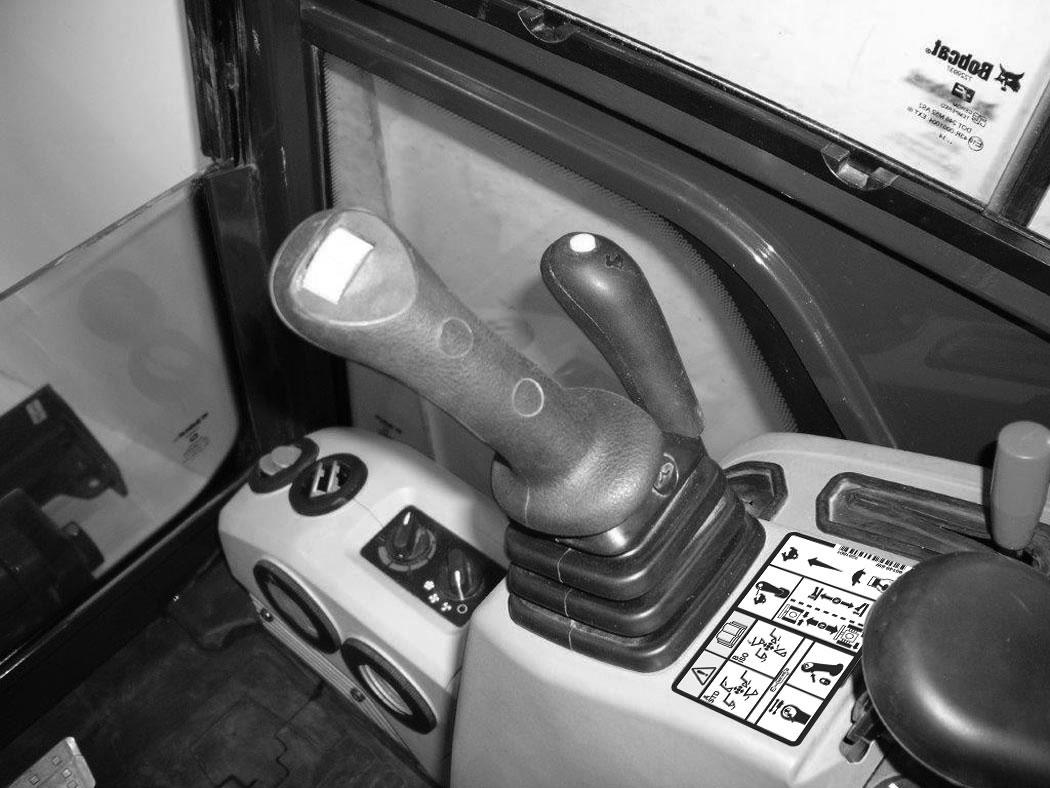
The joystick lock switch disengages the hydraulic control functions from the joysticks when the console are raised [Figure 135]
NOTE: If the engine stops, the boom / bucket (attachments) can be lowered to the ground using hydraulic pressure in the accumulator.
The control console must be in the locked down position, and the key switch in the ON position.
Use the control lever to lower the boom. Lower the control console to engage the hydraulic control functions of the joysticks [Figure 135]

OPERATING PROCEDURE (CONT’D)
Object Handling
The excavator must be equipped with the optional lift eye link (Item 1) [Figure 136], the boom and arm load hold valves and the overload warning device option. See your Bobcat dealer for available Kits.
Do not exceed the Rated Lift Capacity. (See MACHINE SIGNS (DECALS) on Page 16.)
Warning
AVOID INJURY OR DEATH
•Do not exceed rated lift capacity.
•Excessive load can cause tipping or loss of control.
•Excessive load can cause failure of the lift eye and cause the load to drop.
W-2991-0714
Extend the bucket cylinder completely and lower the boom to the ground. Stop the engine. Exit the excavator. (See STOPPING THE ENGINE AND LEAVING THE EXCAVATOR on Page 69.)
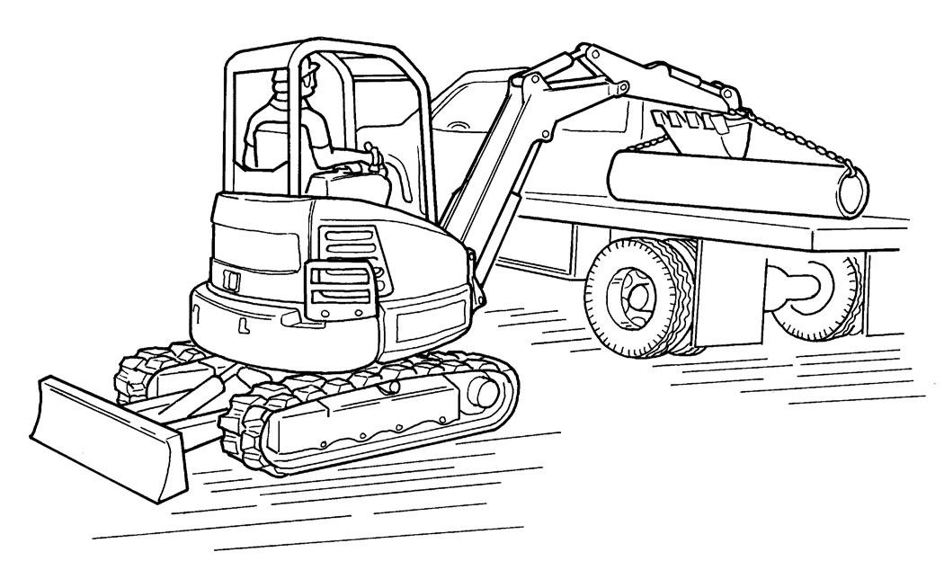
Figure 136
Install a clevis (Item 3) through the lift eye (Item 1) [Figure 136].
NOTE: Visually check the lifting eye, the clevis and the lifting chain (lifting device) for any damage. Replace any damage components before lifting.
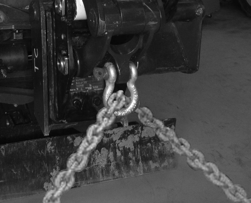
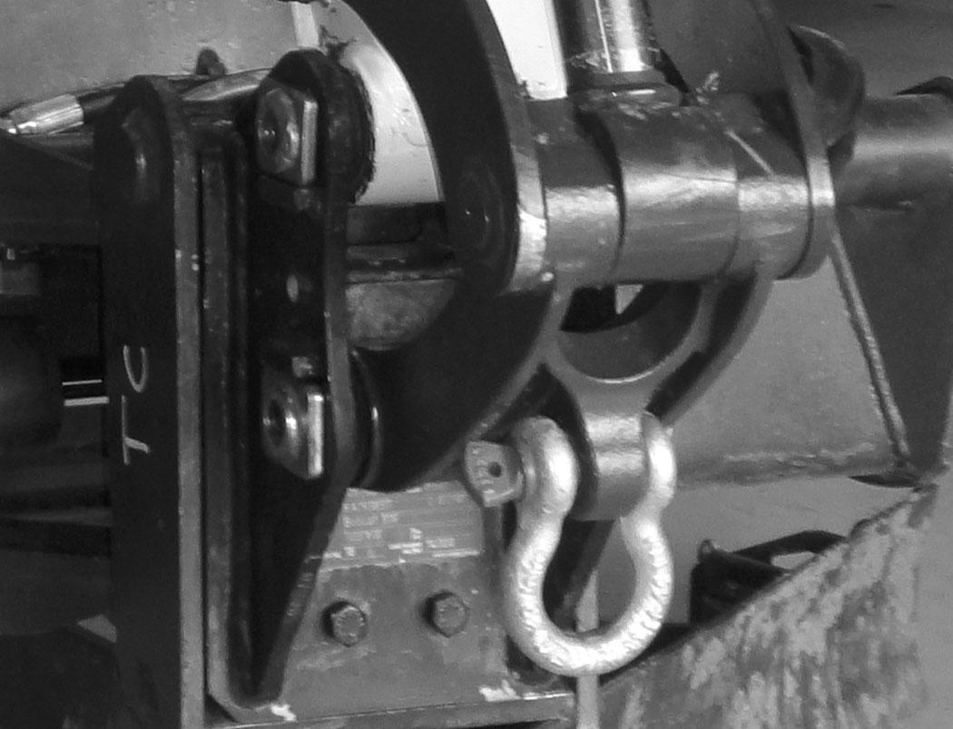
Figure 137
Install a lift chain (Item 1) (or other type of lifting device) through the clevis (Item 2) [Figure 137] and connect to the object to be lifted.
NOTE:Always use chains or other types of lifting devices that are intended for this type of use and that are of adequate strength for the object being lifted.
Enter the excavator, fasten the seat belt and start the engine. (See PRE-STARTING PROCEDURE on Page 62.)
Press the switch (Item 2) [Figure 136] to the left to activate the overload warning device.
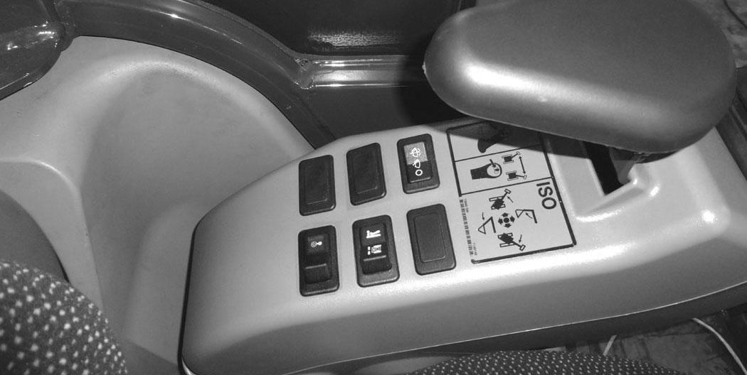
Figure 138
Make sure the load is evenly weighted and centred on the lifting chain (or other type of lifting device), and is secured to prevent the load from shifting [Figure 138]
Operate the controls slowly and smoothly to avoid suddenly swinging the lifted load.
Lift and position the load. When the load is placed in a secured position and tension is removed from the lift chain, remove the chain from the load and from the lift eye.
OPERATING PROCEDURE (CONT’D)
Lift Capacity
The lifting capacities were calculated with a Standard Configuration Machine (machine equipped with pin-on interface and no attachment). The weight of the attachment, hydraulic clamp (if equipped) and different interface (if equipped) must be subtracted from the lift capacity, to obtain the actual lift capacity.
AVOID INJURY OR DEATH
Do not exceed rated lift capacity. Excessive load can cause tipping or loss of control.
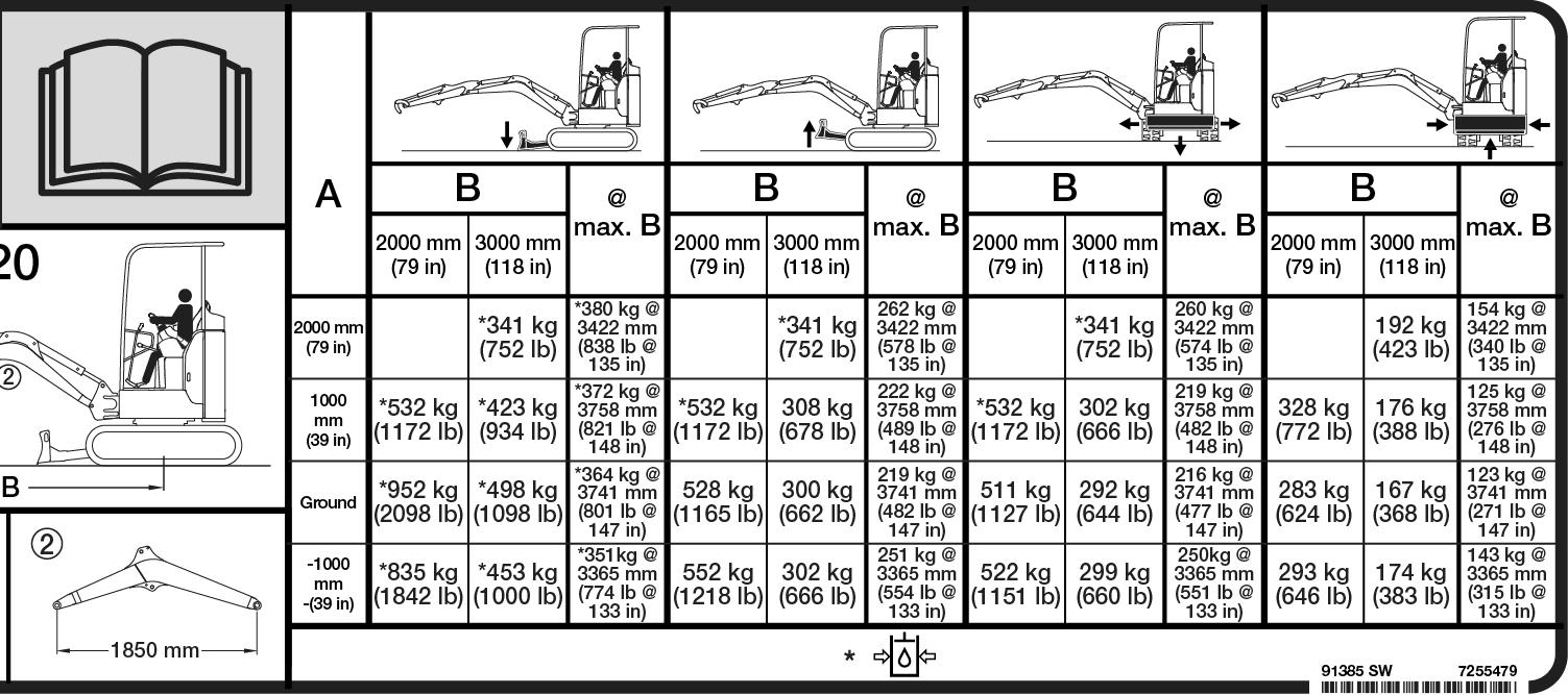
EXAMPLE OF LIFT CAPACITY
* 423 kg (934 lb)
Detailed information about Quick Coupler and hydraulic clamp weights can be found in documentation including its serial number plates.The following lists examples of the optional quick couplers and hydraulic clamp weights:
•German Style Quick Coupler = 18 kg (40 lb)
•Klac™ Quick Coupler (BQC) Type K) = 16 kg (35 lb)
•Mechanical Pin Grabber Coupler = 18 kg (40 lb)
•Hydraulic Clamp And Cylinder = 32 kg (71 lb)
•Optional Buckets and Attachments (See NOTE below)
NOTE:For bucket weights, see your Bobcat dealer. For attachment weights, see the attachment Operation & Maintenance Manual.
The following example will show how to calculate the lift capacity differences between the lift capacity charts with standard equipment and when using optional equipment.
OPERATING PROCEDURE (CONT’D)
Lift Capacity (Cont’d)
The following is an example for determining the actual lift capacity using the sample chart shown above [Figure 139]
- Machine Position: Over Blade, Tracks Expanded, Blade Down
- Lift Radius: 3000 mm (118 in)
- Lift Point Height: 1000 mm (39 in)
- Hydraulic Clamp and Cylinder
- Standard Bucket
1. Obtain Lift Capacity from Chart: 423 kg (934 lb)
2. Obtain the weights of optional equipments which reduce the lift capacity of the machine (coupling interface, hydraulic clamp, attachment).
Optional Equipment Weights: Standard Bucket 42 kg (92 lb), attachment coupler system 18 kg (40 lb), Hydraulic Clamp and Cylinder 32 kg (71 lb)
3. Calculate the actual lift capacity by subtracting the weight of optional equipments from the lift capacity of standard configuration.
423 kg (934 lb) - 42 kg (92 lb) (standard bucket) - 18 kg (40 lb) (attachment coupler system) - 32 kg (71 lb) (hydraulic clamp and cylinder) = 331 kg (731 lb)
* The lift capacity charts (decals) are based off of ISO 10567: 2007. The lifting capacities are defined as the lower value of 75% of tipping load or 87% of the hydraulic lift capacity.
OPERATING PROCEDURE (CONT’D)
Using The Clamp
Figure 140
Using Right Joystick Switch To Activate Clamp
Engage auxiliary hydraulics. (See Auxiliary HydraulicsJoystick Controls on Page 47.)
141
The optional lifting clamp attachment gives the excavator a wider range of use and mobility for debris removal [Figure 140]
The lifting clamp cylinder must be fully retracted when the machine is being used for excavating.
The lift capacities are reduced by 32 kg (71 lb) if the excavator is equipped with the optional lifting clamp.
If equipped with the switch in the right joystick, move the switch (Item 1) [Figure 141] to the right to open the clamp. Move the switch to the left to close the clamp.
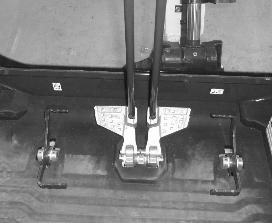
Using Auxiliary Hydraulic Pedal To Activate Clamp
142
If equipped, the auxiliary hydraulic pedal (Item 1), controls the hydraulic clamp. Press the toe (Item 2) of the auxiliary hydraulic pedal to open the clamp. Press the heel (Item 3) [Figure 142] of the pedal to close the clamp.
OPERATING PROCEDURE (CONT’D)
Driving The Excavator
When operating on uneven ground, operate as slow as possible and avoid sudden changes in direction. Avoid travelling over objects such as rocks, trees, stumps, etc.
When working on wet or soft ground, put planks on the ground to provide a solid base to travel on and prevent the excavator from getting stuck.
NA1440
If one or both tracks have become stuck in soft or wet ground, raise one track at a time by turning the upperstructure and pushing the bucket against the ground [Figure 143]
Put planks under the tracks and drive the excavator to dry ground.
NA1422
The bucket can also be used to pull the excavator. Raise the blade, extend the arm and lower the boom. Operate the boom and arm in a digging manner [Figure 144]
OPERATING PROCEDURE (CONT’D)
Operating On Slopes
Warning
AVOID INJURY OR DEATH
•Do not travel across or up slopes that are over 15 degrees.
•Do not travel down or back up slopes that exceed 25 degrees.
•Look in the direction of travel.
W-2497-0304
When going down a slope, control the speed with the steering levers and the speed control dial gauge.
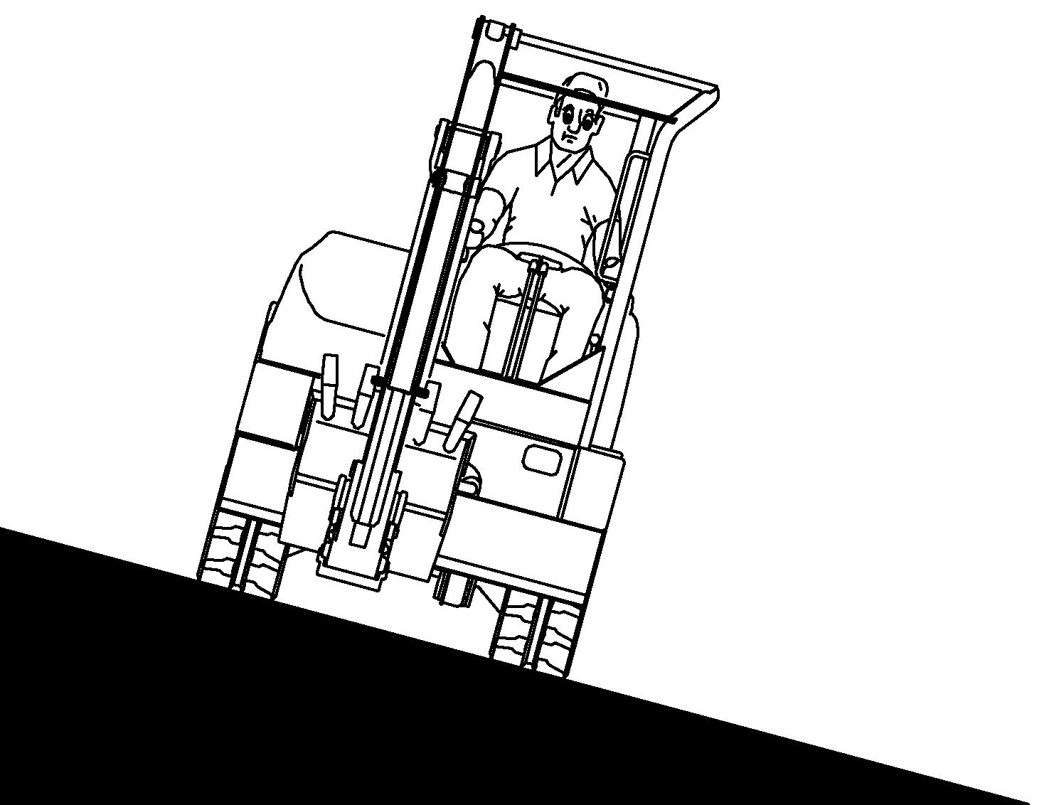
Travelling Down or Backing Up Slopes
Warning
AVOID INJURY OR DEATH
•Avoid steep areas or banks that could break away.
•Keep boom centred and attachments as low as possible when travelling on slopes or in rough conditions. Look in the direction of travel.
•Always fasten seat belt.
W-2498-EN-1009
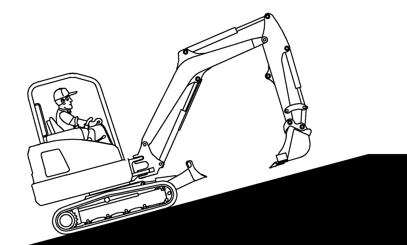
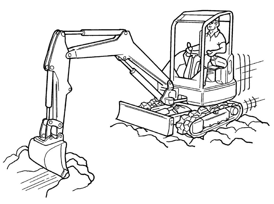
When going down grades that exceed 15 degrees, put the machine in the position shown, and run the engine slowly [Figure 145].
Operate as slow as possible and avoid sudden changes in lever direction.
Avoid travelling over objects such as rocks, trees, stumps, etc.
Stop the machine before moving the upper equipment controls. Never allow the blade to strike a solid object. Damage to the blade or hydraulic cylinder can result.
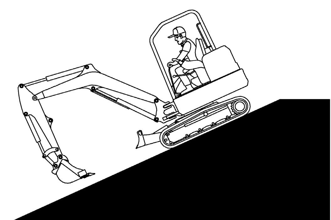
When travelling up slopes or on side slopes that are 15 degrees or less, position the machine as shown and run the engine slow [Figure 146] and [Figure 147]