9 minute read
MOTION ALARM SYSTEM Operation


Warning
This machine is equipped with a motion alarm. ALARM MUST SOUND! when operating forward or backward.
Failure to maintain a clear view in the direction of travel could result in serious injury or death.
The operator is responsible for the safe operation of this machine.
W-2786-0309
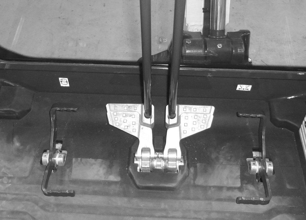
The motion alarm will sound when the operator moves the travel control levers (Item 1) [Figure 33] in either the forward or reverse direction.
If alarm does not sound or for adjustment instructions, see inspection and maintenance instructions for the motion alarm system in the preventive maintenance section of this manual. (See MOTION ALARM SYSTEM on Page 105.)
Travel Controls
Forward And Reverse Travel
NOTE:The following procedures describe forward, reverse, left and right as seated in the operator’s seat.
Put the blade so that it is at the front of the machine (as you sit in the operator’s seat). Slowly move both steering levers* (Item 1) [Figure 33] forward for forward travel; backward for reverse travel.

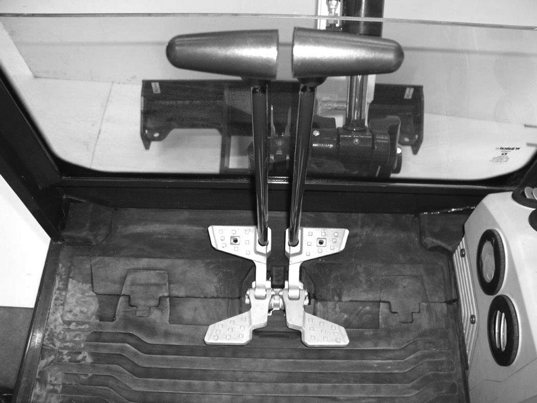
* Travel can also be controlled with foot pedals (Item 2) [Figure 33]. Pivot the heel of the pedals forward for additional space on the floor.
Warning
AVOID INJURY OR DEATH
•Check the blade location before travelling. When the blade is to the rear, operate the steering levers / foot pedals in the opposite direction to when the blade is in the front.
•Move the steering levers / foot pedals slowly. Abrupt lever motion will cause the machine to jerk.
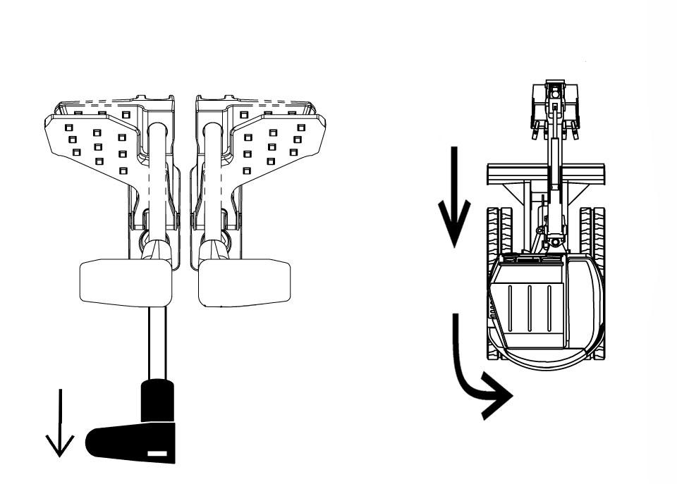
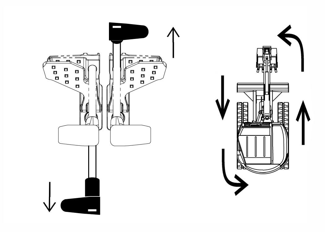
Push the left steering lever forward to turn right [Figure 34] while travelling forward.
Pull the left steering lever backward to turn right while travelling backward [Figure 35]
TRAVEL CONTROLS (CONT’D)
Turning (Cont’d)
Counter-Rotation Right Turn
Figure 36
38
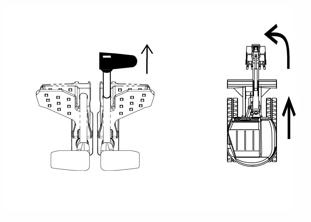
Push the left steering lever forward and pull the right steering lever backward [Figure 36] Left Turn
Figure 37
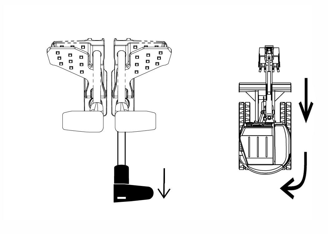
Pull the right steering lever backward to turn left while travelling backward [Figure 38]
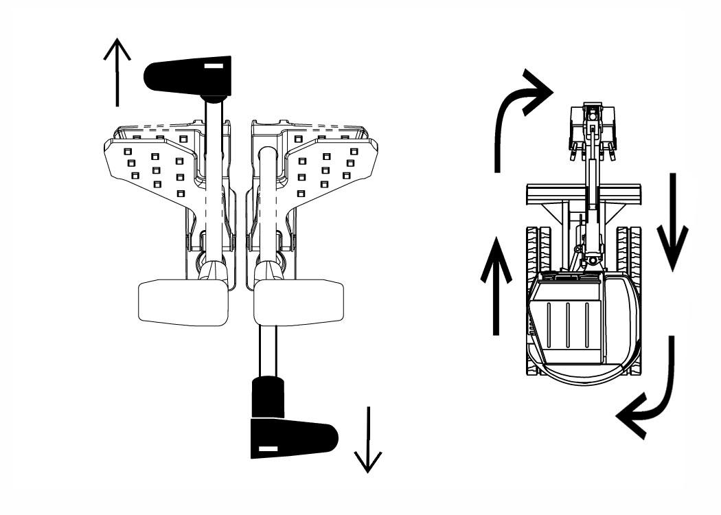
Counter-Rotation Left Turn
Figure 39
Push the right steering lever forward to turn left while travelling forward [Figure 37]
Push the right steering lever forward and pull the left steering lever backward [Figure 39]
HYDRAULIC CONTROLS Description
The work equipment (boom, arm, bucket, and upperstructure slew) is operated by using the left and right control levers (joysticks).
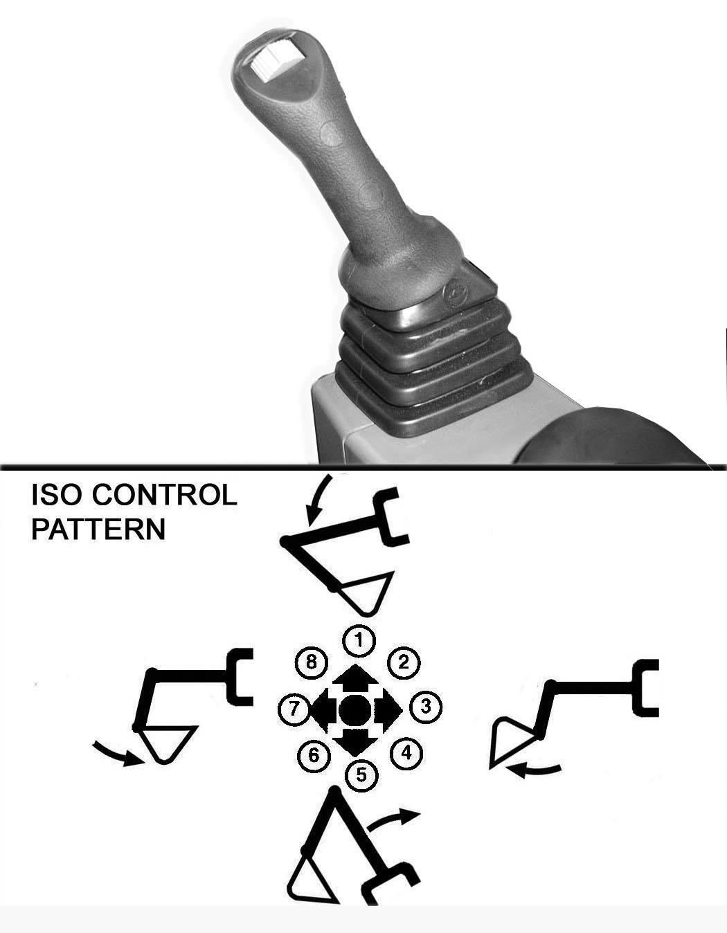
ISO Control Pattern
Left Control Lever (Joystick)
Figure 40
Iso Control Pattern
The left lever (joystick) is used to operate the arm and slew the upperstructure [Figure 40].
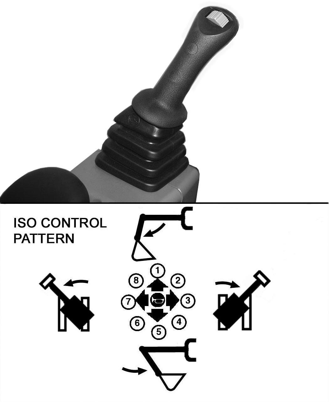
Right Control Lever (Joystick)
Figure 41
Iso Control Pattern
41]
1. Boom lower.
2. Boom lower and bucket dump.
3. Bucket dump.
4. Boom raise and bucket dump.
5. Boom raise.
6. Boom raise and bucket curl.
7. Bucket curl.
8. Boom lower and bucket curl.
Warning
AVOID INJURY OR DEATH
Before leaving the machine:
•Lower the work equipment to the ground.
•Lower the blade to the ground.
•Stop the engine and remove the key.
•Raise the control console.
W-2780-0109
HYDRAULIC CONTROLS (CONT’D)
Quick Couplers
Warning
AVOID BURNS
Hydraulic fluid, tubes, fittings and quick couplers can get hot when running machine and attachments. Be careful when connecting and disconnecting quick couplers.
W-2220-0396
Warning
AVOID INJURY OR DEATH
Diesel fuel or hydraulic fluid under pressure can penetrate skin or eyes, causing serious injury or death. Fluid leaks under pressure may not be visible. Use a piece of cardboard or wood to find leaks. Do not use your bare hand. Wear safety goggles. If fluid enters skin or eyes, get immediate medical attention from a doctor familiar with this injury.
W-2072-EN-0909
42
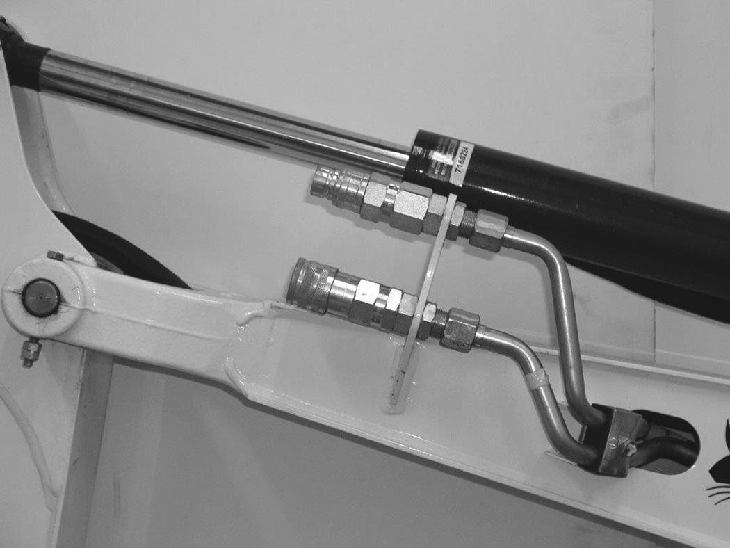
The excavator is supplied with hydraulic lines (Item 1) [Figure 42] that supply the hydraulic fluid for attachments.
Optional flush faced couplers (Item 2) [Figure 42] are available. See your Bobcat dealer for flush face couplers.
To Connect:
If equipped with flush face couplers, remove any dirt or debris from the surface of both the male and female couplers, and from the outside diameter of the male coupler. Visually check the couplers for corroding, cracking, damage, or excessive wear, if any of these conditions exist, the coupler(s) (Item 2) [Figure 42] must be replaced.
Install the male coupler into the female coupler. Full connection is made when the ball release sleeve slides forward on the female coupler.
To Disconnect:
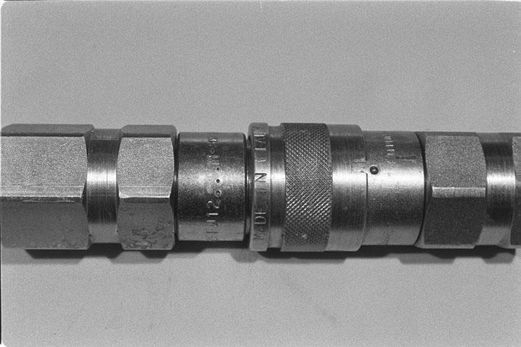
Figure 43
Hold the male coupler (Item 1). Retract the sleeve (Item 2) [Figure 43] on the female coupler until the couplers disconnect.
HYDRAULIC CONTROLS (CONT’D)
Auxiliary Hydraulics - Joystick Controls
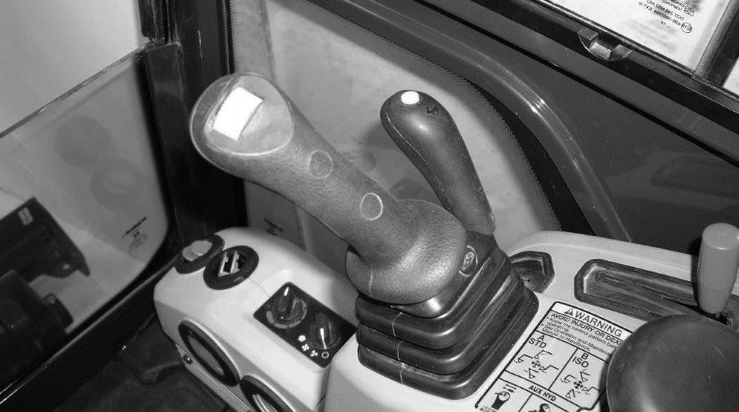
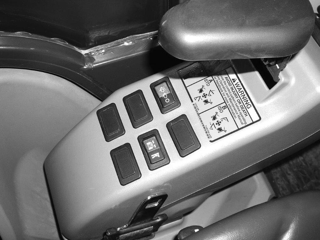
If equipped with the auxiliary hydraulic switch (Item 1) [Figure 45] see the following information. If equipped with the auxiliary hydraulic pedal (Item 1) [Figure 47] (See Auxiliary Hydraulics - Manual Controls on Page 48.)
Continuous Hydraulic Flow
Press the button (Item 2) [Figure 45] on the front of the handle to provide continuous flow to the female coupler.
NOTE: Pressing the switch (Item 1) to the left while pressing the button (Item 2) [Figure 45] on the front of the handle will provide continuous flow to the male coupler.
Press the button (Item 2) [Figure 45] a second time to stop auxiliary flow to the quick couplers.
NOTE:Reverse flow can cause damage to some attachments. Use reverse flow with your attachment only if approved. See your attachment Operation & Maintenance Manual for detailed information.
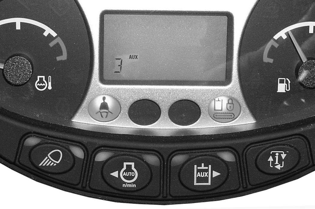
To change the auxiliary flow, press the Auxiliary Hydraulics button (Item 1) to toggle through the settings, each time the button is pressed, the next setting will appear in the data display (Item 2) [Figure 44]. Once the desired setting is selected, it will stay at that setting until a different auxiliary flow is selected by the operator. (Example: Even if the engine was STOPPED, if Aux2 has been selected, after key OFF and engine restart, the Aux2 setting will still be the active hydraulic flow when the machine is started.)
Examples For Selecting Auxiliary Hydraulic Flow And The Attachments Used:
Aux Flow Setting Flow Attachments
NOTE:Use only approved attachments for your model excavator. Attachments are approved for each model of excavator based on various factors. Using unapproved attachments could cause damage to the attachment or to the excavator.
Selectable Auxiliary Hydraulics Flow
Press the auxiliary hydraulics button (Item 1) once to enable the selectable hydraulic flow. The light (Item 3) [Figure 44] will be illuminated when the selectable auxiliary hydraulics are enabled.
Press the button (Item 1) a second time to disable the auxiliary hydraulics. The light (Item 3) [Figure 44] will turn OFF.

NOTE:If the auxiliary hydraulics are enabled when the engine is turned OFF, they will stay enabled when the engine is restarted.
Press the Auxiliary Hydraulics button (Item 1) (an audible beep will sound each time the auxiliary button is pressed). The last selected auxiliary hydraulic flow (Aux3, Aux2 or Aux1) will appear in the data display (Item 2). The light (Item 3) [Figure 44] will be illuminated.
Move the switch (Item 1) [Figure 45] on the right control lever to the right to supply hydraulic flow to the female coupler. Move the switch to the left to supply hydraulic flow to the male coupler. If you move the switch halfway, the auxiliary functions move at approximately one-half speed.
Press the button (Item 2) [Figure 45] on the front of the handle to provide continuous selectable flow to the female coupler.
NOTE: Pressing the switch (Item 1) to the left while pressing the button (Item 2) [Figure 45] on the front of the handle will provide continuous selectable flow to the male coupler.
Press the button (Item 2) [Figure 45] a second time to stop auxiliary flow to the quick couplers.
HYDRAULIC CONTROLS (CONT’D)
Relieve Hydraulic Pressure - With Joystick Controls (Excavator And Attachment)
NOTE: The following is for auxiliary hydraulics with the joystick switch (Item 1) [Figure 45] only. For manual auxiliary hydraulic controls, see [Figure 47].
Excavator:
Put the attachment flat on the ground.
Stop the engine and turn the key switch to ON.
NOTE: The left console must be fully lowered for relieving hydraulic pressure.
NOTE:Excavator engine must have recently been started to relieve hydraulic pressure.
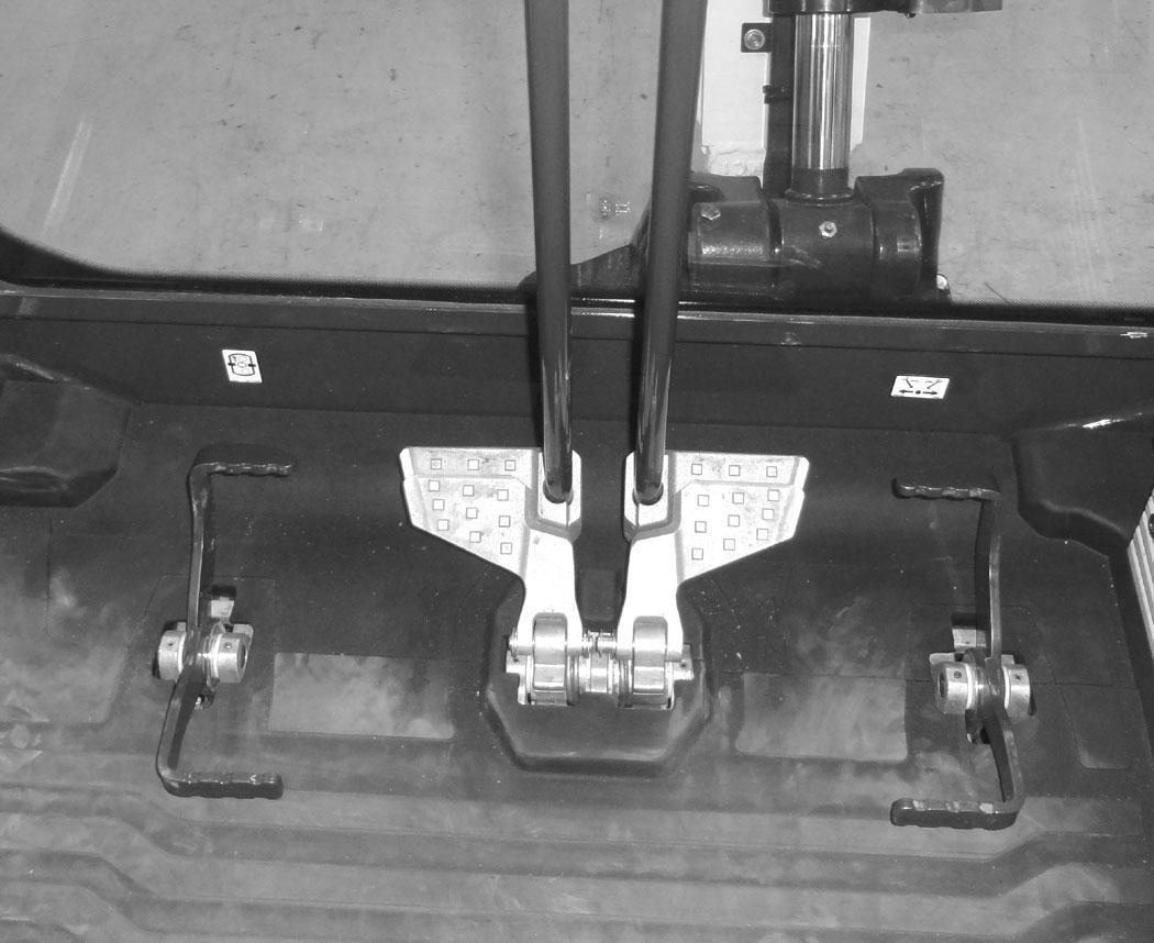
Auxiliary Hydraulics - Manual Controls
If equipped with the auxiliary hydraulic pedal (Item 1) [Figure 47] control, see the following information. If equipped with the joystick auxiliary hydraulic switch (Item 1) [Figure 45] (See Auxiliary Hydraulics - Joystick Controls on Page 47.)
If the auxiliary hydraulics are disabled, press AUX HYD button (Item 1) [Figure 46] and then move the switch (Item 1) [Figure 45] to the right and left several times.

If the auxiliary hydraulics are enabled, then move the switch (Item 1) [Figure 45] to the right and left several times.
Attachments:
•Follow procedure above to relieve hydraulic pressure in excavator.
•Connect male coupler from attachment to female coupler of excavator then repeat procedure above. This will relieve pressure in the attachment.
•Connect the female coupler from the attachment.
Hydraulic pressure in the auxiliary hydraulic system can make it difficult to engage quick couplers to an attachment.
Press the toe of the pedal (Item 2) [Figure 47] to supply hydraulic flow to the female coupler (if equipped).
Press the heel of the pedal (Item 3) [Figure 47] to supply hydraulic flow to the male coupler (if equipped).
Relieve Hydraulic Pressure - With Manual Controls (Excavator And Attachment)
Put the attachment flat on the ground.
Stop the engine.
Excavator:
With the engine off, move the pedal (Item 1) [Figure 47] in both directions several times.
Attachments:
•Follow the procedure above to release pressure in the excavator.
•Connect the male coupler from attachment to the female coupler of the excavator. Then repeat procedure above. This will release pressure in the attachment.
•Connect the female coupler from the attachment.
Hydraulic pressure in the auxiliary hydraulic system can make it difficult to engage quick couplers to an attachment.
HYDRAULIC CONTROLS (CONT’D)
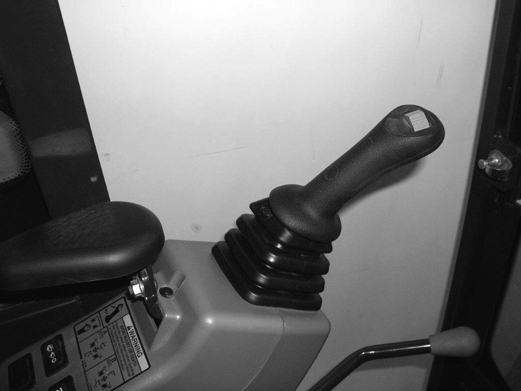
Secondary Auxiliary Hydraulics
When equipped with secondary auxiliary hydraulics, the second set of hydraulic couplers will be mounted on the right side of the arm.
Depending on how the machine is configured, there are two different control options available for the secondary auxiliary hydraulic controls.
1. Using the left joystick switch (Item 1) [Figure 49], or
2. Using the right foot pedal (Item 2) [Figure 49]. Figure 48

Press Boom Swing / Second Auxiliary Hydraulic switch (Item 1) [Figure 48] (if equipped) to the right, secondary auxiliary hydraulic position.
NOTE:The secondary auxiliary hydraulic circuit is for use with attachments that require less than 150 bar (2175 psi) hydraulic pressure for correct operation.
NOTE:An optional orifice kit is available to restrict the hydraulic flow for certain attachments. See your Bobcat dealer for available parts.
NOTE:If equipped with the optional secondary auxiliary orifices (which are used for reducing hydraulic flow to and from the secondary hydraulic couplers for some attachment applications), these orifices can only be used with select attachments that have a control valve that includes internal port relief valves or internal cross port relief valves to prevent high pressure spikes coming from external loads.
When Equipped With Joystick Switch (Item 1) [Figure 49]:
Move the switch (Item 1) [Figure 49] on the left joystick to the left to supply hydraulic flow to the female coupler. Move the switch to the right to supply hydraulic flow to the male coupler. If you move the switch halfway, the auxiliary functions move at approximately one-half speed.
When Equipped With Boom Swing / Secondary Auxiliary Pedal (Item 2):
Press the toe of the pedal (Item 3) [Figure 49] to supply hydraulic flow to the female coupler.
Press the heel of the pedal (Item 4)[Figure 49] to supply hydraulic flow to the male coupler.
NOTE:The 2nd auxiliary circuit is not suitable for continuous application and attachment use.
HYDRAULIC CONTROLS (CONT’D)
Relieve Secondary Auxiliary Hydraulic Pressure (Excavator And Attachment)
NOTE:Hydraulic pressure in the secondary auxiliary hydraulic system can make it difficult to engage quick couplers to an attachment.
NOTE:The following is for secondary auxiliary hydraulics with the joystick switch (Item 1) [Figure 50] only. For manual secondary auxiliary hydraulic controls, see [Figure 51].
Excavator:
Put the attachment flat on the ground.
Stop the engine and turn the key switch to ON.
NOTE:The left console must be fully lowered for relieving hydraulic pressure.
NOTE:Excavator engine must have recently been started to relieve hydraulic pressure.
Figure 50
Press Boom Swing / Second Auxiliary Hydraulic button to the secondary auxiliary position (Item 1) [Figure 50] and then move the joystick switch (Item 2) [Figure 50] to the right and left several times.
Attachments:
•Follow procedure above to relieve hydraulic pressure in excavator.
•Connect male coupler from attachment to female coupler of excavator then repeat procedure above. This will relieve pressure in the attachment.
•Connect the female coupler from the attachment.
Relieve Secondary Hydraulic Pressure - With Manual Controls (Excavator And Attachment)
Figure 51
Put the attachment flat on the ground. Stop the engine.
Turn the key switch to ON.
NOTE:The left console must be fully lowered for relieving hydraulic pressure.
NOTE:Excavator engine must have recently been started to relieve hydraulic pressure.
Excavator:
Move the pedal (Item 1) [Figure 51] in both directions several times.
Attachments:
•Follow the procedure above to release pressure in the excavator.
•Connect the male coupler from attachment to the female coupler of the excavator. Then repeat procedure above. This will release pressure in the attachment.
•Connect the female coupler from the attachment.
Engine Speed Control
Setting Engine Speed (RPM)
Figure 52
The engine speed control lever (Item 1) [Figure 52] controls engine rpm.
Move the engine speed control lever back (Item 2) to reduce engine rpm. Move the engine speed control dial forward (Item 3) [Figure 52] to increase engine rpm.
Blade Control Lever


Raising And Lowering Blade
Figure 53
Push the Blade / Track Retraction - Expansion Switch (Item 1) [Figure 53] to the Blade position.
Figure 54
Move the Blade / Track Retraction - Expansion Lever forward to lower the blade [Figure 54]
Move the Blade / Track Retraction - Expansion Lever backward to raise the blade [Figure 54]
NOTE: Keep blade lowered for increased digging performance.