13 minute read
STOPPING THE ENGINE AND LEAVING THE EXCAVATOR


Procedure
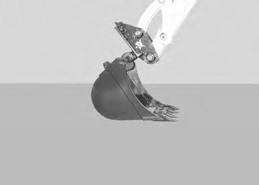
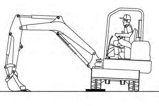
Expand the tracks fully. Stop the machine on level ground. Lower the work equipment and the blade to the ground [Figure91]
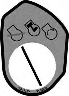
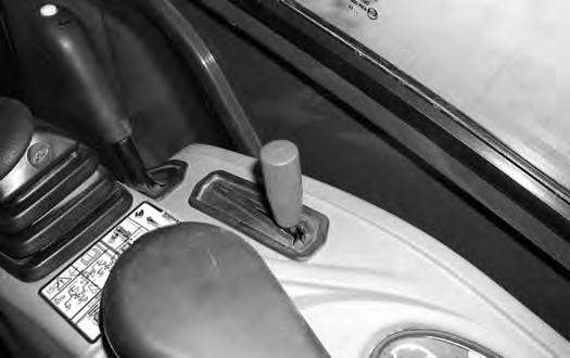
Turn the switch to STOP [Figure93]
Disconnect the seat belt. Remove the key from the switch (If Equipped) to prevent operation of machine by unauthorized personnel. Raise the control console and exit the machine.
Run the engine at idle speed for about 5 minutes to allow it to cool.
Attachments
Installing And Removing The Attachment (Pin-On Attachment)
Installation
Warning
AVOID INJURY OR DEATH
Stop the machine on a firm flat surface. When removing or installing attachments (such as a bucket), always have a second person in the operator’s seat, give clear signals and work carefully.
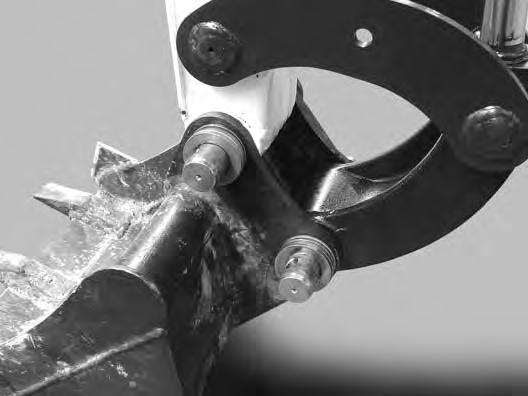
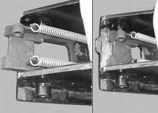
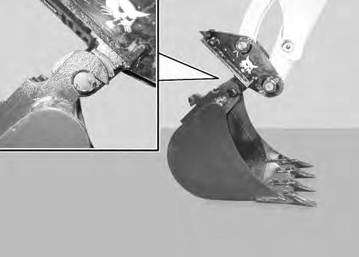
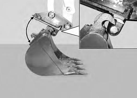
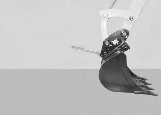
Install the arm into the bucket and align the mounting hole.
Install the pin (Item 1) [Figure94] and washers.
Install the link (Item 2) in the bucket and align the mounting hole. Install the pin (Item 3) [Figure94] and washers
Removal
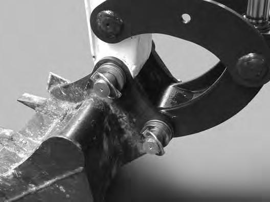
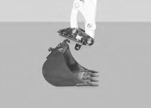
Park the excavator on a flat surface and lower the bucket fully.
Remove the two retainer pins (Item 1) [Figure95]
Remove the washers and pins (Items 1 and 3) [Figure94]
Do not damage the dust seals in the arm.
Warning
AVOID INJURY OR DEATH
Never use attachments or buckets which are not approved by Bobcat Company. Buckets and attachments for safe loads of specified densities are approved for each model. Unapproved attachments can cause injury or death.
W-2052-0907
ATTACHMENTS (CONT’D)
Bobcat Quick Coupler (BQC) Type SW
Warning
AVOID INJURY OR DEATH
Never use attachments or buckets which are not approved by Bobcat Company. Buckets and attachments for safe loads of specified densities are approved for each model. Unapproved attachments can cause injury or death.
W-2052-0907
Warning
AVOID INJURY OR DEATH
Stop the machine on a firm flat surface. When removing or installing attachments (such as a bucket), always have a second person in the operator’s seat, give clear signals and work carefully.
W-2140-0189
NOTE:Installation and removal of a bucket is shown. The procedure for other attachments is similar. Disconnect all hydraulic connections prior to removing the attachment (breaker, auger, etc.)
Installation
Step 1: Preparation
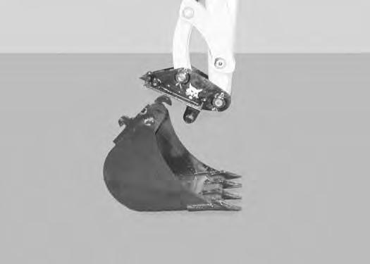
Park the excavator on a level surface and put the bucket flat on the ground.
Start the engine.
Fully retract the bucket cylinder.
Step 2: Connecting
Figure96
S3013
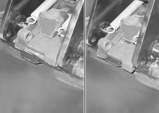
Lower the BQC (Item 1) onto the adapter (Item 2) [Figure96] of the bucket.
S3014
Engage
ATTACHMENTS (CONT’D)
Bobcat Quick Coupler (BQC) Type SW (Cont’d)
Installation (Cont’d)
Figure98
Extend the bucket cylinder and lift the boom until the top of the BQC (Item 1) engages the edge (Item 2) [Figure98] of the bucket adapter.
Step 3: Securing
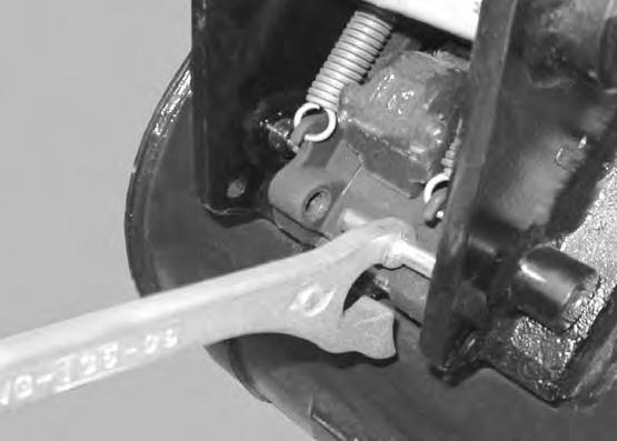
Figure99
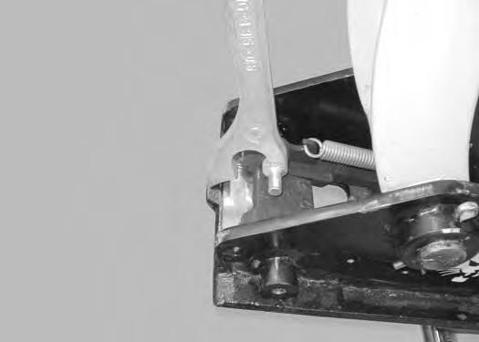
Insert the socket wrench (Item 1) [Figure99] into the locking plate and turn clockwise until the locking pins are engaged. Visually check to ensure that the locking pins are fully engaged.
Removal
Park the excavator on a level surface and put the bucket flat on the ground.
Figure100
Raise and tilt in the bucket [Figure100]
Figure101
Insert the socket wrench (Item 1) [Figure101] into the locking plate and turn counterclockwise to let the locking come loose.
ATTACHMENTS (CONT’D)
Bobcat Quick Coupler (BQC) Type SW (Cont’d)
Removal (Cont’d)
ATTACHMENTS (CONT’D)
Installing And Removing The Attachment (Bobcat Quick Coupler (BQC) Type K)
Installation
NOTE: Installation and removal of the bucket is shown. The procedure is the same for other attachments. Disconnect any hydraulic lines that are operated by hydraulic power before removing any attachments (breaker, auger etc.).
Warning
AVOID INJURY OR DEATH
Never use attachments or buckets which are not approved by Bobcat Company. Buckets and attachments for safe loads of specified densities are approved for each model. Unapproved attachments can cause injury or death.
Warning
AVOID INJURY
Keep fingers and hands out of pinch points when latching and unlatching the attachment quick coupler.
Fully retract the bucket cylinder. Stop the engine and exit the excavator.
Inspect the quick coupler to make sure the latch is in the unlatched position (Item 1) [Figure105]
If in the latched position, see [Figure106] for additional information.
If the latch is in the unlatched position, proceed to [Figure107]
To unlatch the quick coupler, install the tool (Item 1) [Figure106] and pull the handle. The latch will move completely forward. The latch will lock in the unlatched position.
Enter the excavator, fasten the seat belt and start the engine.
Position the quick coupler (Item 1) to the attachment (Item 2) [Figure107]
ATTACHMENTS (CONT’D)
Installing And Removing The Attachment (Bobcat Quick Coupler (BQC) Type K) (Cont’d)
Installation (Cont’d)
Figure108
There must be at least 100 between the quick coupler surface (Item 1) and the attachment mounting surface (Item 2) [Figure108]. Extend the arm out to get the required angle for proper installation.
NOTE: There must be proper clearance (100 minimum) between the hook (Item 3) and the quick coupler (Item 4) [Figure108]. Possible damage to the attachment hooks or the quick coupler could occur without proper clearance.
Raise the boom until there is approximately 20.0 inches (500 mm) of clearance between the bottom of the attachment and the ground [Figure110].
Raise the boom and extend the arm until the hooks of the attachment (Item 1) engage the pins (Item 2) of the quick coupler [Figure109]
Extend the bucket cylinder (Item 1) [Figure111] fully.
Lower the attachment until it is flat on the ground.
Engage the parking brake.
Stop the engine and exit the excavator.
ATTACHMENTS (CONT’D)
Installing And Removing The Attachment (Bobcat Quick Coupler (BQC) Type K) (Cont’d)
Installation (Cont’d)
Figure112
Figure113
Visually inspect the quick coupler latch (Item 1) to the bucket mount (Item 2) [Figure112]. The latch must be fully engaged.
If the latch is not engaged, install the tool (Item 1) in the hole (Item 2) [Figure113] of the quick coupler and push down to unlatch the quick coupler. Remove the tool. Enter the excavator, fasten the seat belt and start the engine. Raise the attachment 20.0 inches (500 mm) off of the ground and fully extend the bucket cylinder. Lower the attachment until it is flat on the ground. Engage the parking brake. Stop the engine and exit the excavator.
AVOID INJURY
Keep fingers and hands out of pinch points when latching and unlatching the attachment quick coupler.
W-2541-1106
Again, visually inspect the quick coupler to make sure the latch (Item 1) [Figure112] is fully engaged. If it is not fully engaged, remove the attachment and inspect both the quick coupler and the attachment for damage or debris. (See [Figure117] for Quick Coupler And Attachment Inspection information.)
ATTACHMENTS (CONT’D)
Installing And Removing The Attachment (Bobcat Quick Coupler (BQC) Type K) (Cont’d)
Removal
Warning
AVOID INJURY
Keep fingers and hands out of pinch points when latching and unlatching the attachment quick coupler.
Position the attachment flat on the ground.
Install the quick coupler tool (Item 1) into the hole (Item 2) [Figure113] in the quick coupler.
Push down on the tool (Item 1) [Figure114] to unlock the latch.
Remove the tool.
Enter the excavator, fasten the seat belt and start the engine.
Retract the bucket cylinder fully and lower the boom [Figure115] until the attachment is on the ground.
Continue to lower the boom and move the arm towards the excavator until the quick coupler is clear of the attachment [Figure116].
ATTACHMENTS (CONT’D)
Installing And Removing The Attachment (Bobcat Quick Coupler (BQC) Type K) (Cont’d)
Quick Coupler And Attachment Inspection
Inspect the quick coupler for wear or damage. Inspect the quick coupler pins (Item 1) and the hooks (Item 2) [Figure117] (on the attachment) for wear or damage.
Repair or replace damaged parts.
OPERATING PROCEDURE Inspect The Work Area
Before beginning operation, inspect the work area for unsafe conditions.
Look for sharp drop-offs or rough terrain. Have underground utility lines (gas, water, sewer, irrigation, etc.) located and marked. Work slowly in areas of underground utilities.
Remove objects or other construction material that could damage the excavator or cause personal injury.
Always check ground conditions before starting your work:
•Inspect for signs of instability such as cracks or settlement.
•Be aware of weather conditions that can affect ground stability.
•Check for adequate traction if working on a slope.
Basic Operating Instructions
When operating on a public road or highway, always follow local regulations. For example: A slow moving vehicle (SMV) sign, or direction signals can be required.
Run the engine at low idle speed to warm the engine and hydraulic system before operating the excavator.
Important
Machines warmed up with moderate engine speed and light load have longer life.
I-2015-0284
New operators must operate the excavator in an open area without bystanders. Operate the controls until the excavator can be handled at an efficient and safe rate for all conditions of the work area.
Operating Near An Edge Or Water
Keep the excavator as far back from the edge as possible and the excavator tracks perpendicular to the edge so that if part of the edge collapses, the excavator can be moved back.
Always move the excavator back at any indication the edge may be unstable.
Lowering The Work Equipment (Engine STOPPED)
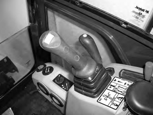
The hydraulic control levers control the movement of the boom, arm, bucket and upperstructure slew functions.
The console must be in the locked down position, and the key switch in the ON position.
Use the control lever to lower the boom.
The joystick lock switch disengages the hydraulic control functions from the joysticks when the console are raised [Figure118].
NOTE: If the engine stops, the boom / bucket (attachments) can be lowered to the ground using hydraulic pressure in the accumulator.
The control console must be in the locked down position, and the key switch in the ON position.
Use the control lever to lower the boom.
Lower the control console to engage the hydraulic control functions of the joysticks [Figure118].

OPERATING PROCEDURE (CONT’D)
Object Handling
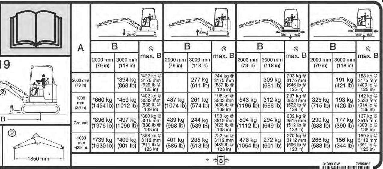
The excavator must be equipped with the optional lift eye link (Item 1) [Figure119], the boom and arm load hold valves and the overload warning device option. See your Bobcat dealer for available Kits.
Do not exceed the Rated Lift Capacity. (See MACHINE SIGNS (DECALS) on Page 20.)
Warning
AVOID INJURY OR DEATH
•Do not exceed rated lift capacity.
•Excessive load can cause tipping or loss of control.
•Excessive load can cause failure of the lift eye and cause the load to drop.
W-2991-0714
Extend the bucket cylinder completely and lower the boom to the ground. Stop the engine. Exit the excavator. (See STOPPING THE ENGINE AND LEAVING THE EXCAVATOR on Page 73.)
Figure119
Install a clevis (Item 3) through the lift eye (Item 1) [Figure119].
NOTE: Visually check the lifting eye, the clevis and the lifting chain (lifting device) for any damage. Replace any damage components before lifting.
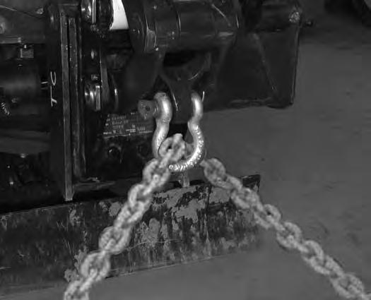
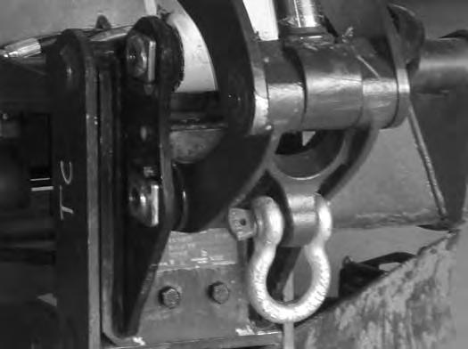
Figure120
Install a lift chain (Item 1) (or other type of lifting device) through the clevis (Item 2) [Figure120] and connect to the object to be lifted.
NOTE:Always use chains or other types of lifting devices that are intended for this type of use and that are of adequate strength for the object being lifted.
Enter the excavator, fasten the seat belt and start the engine. (See PRE-STARTING PROCEDURE on Page 66.)
Press the switch (Item 2) [Figure119] to the left to activate the overload warning device.
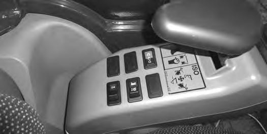
Figure121
Make sure the load is evenly weighted and centered on the lifting chain (or other type of lifting device), and is secured to prevent the load from shifting [Figure121]
Operate the controls slowly and smoothly to avoid suddenly swinging the lifted load.
Lift and position the load. When the load is placed in a secured position and tension is removed from the lift chain, remove the chain from the load and from the lift eye.
OPERATING PROCEDURE (CONT’D)
Lift Capacity
The lifting capacities were calculated with a machine that was equipped with the pin-on interface. The difference between the weight of the attachment, and the hydraulic clamp (if equipped) must be subtracted.
Warning
AVOID INJURY OR DEATH
Do not exceed rated lift capacity. Excessive load can cause tipping or loss of control.
* 459 kg (1012 lb)
7255482
The following example will show how to calculate the lift capacity differences between the lift capacity charts with standard equipment and when using optional equipment.
The standard equipment weights used when determining lift capacity are as follows:
Standard Bucket = 42 kg (92 lb)
The following lists the weight of the optional quick couplers and hydraulic clamp:
•Lehnhoff® Quick Coupler (BQC) Type SW = 18 kg (40 lb)
•Klac™ Quick Coupler (BQC) Type K) = 16 kg (35 lb)
•Hydraulic Clamp And Cylinder = 32 kg (71 lb)
•Optional Buckets and Attachments (See NOTE below)
NOTE:For bucket weights, see your Bobcat dealer. For attachment weights, see the attachment Operation & Maintenance Manual.
OPERATING PROCEDURE (CONT’D)
Lift Capacity (Cont’d)
The following is an example for determining the lift capacity using the sample chart shown above [Figure122]
- Machine Position: Over Blade, Tracks Expanded, Blade Down
- Lift Radius: 3000 mm (118 in)
- Lift Point Height: 1000 mm (39 in)
- Hydraulic Clamp and Cylinder
- Standard Bucket
1. Obtain Lift Capacity from Chart: 459 kg (1012 lb)
2. Subtract the difference between the weight of the standard configuration and optional equipment which in this case is; the Standard Bucket, attachment coupler system (BQC) Type SW) and the Hydraulic Clamp.
Standard machine weight: minus Standard Bucket 42 kg (92 lb), minus attachment coupler system 18 kg (40 lb), minus Hydraulic Clamp and Cylinder: 32 kg (71 lb)
3. Calculate actual Lift Capacity for machine as configured:
459 kg (1012 lb) - 42 kg (92 lb) (standard bucket) - 18 kg (40 lb) (attachment coupler system) - 32 kg (71 lb) (hydraulic clamp and cylinder) = 367 kg (809 lb)
* The lift capacity charts (decals) are based off of ISO 10567: 2007. The lifting capacities are defined as the lower value of 75% of tipping load or 87% of the hydraulic lift capacity.
OPERATING PROCEDURE (CONT’D)
Using The Clamp
Figure123
Using Right Joystick Switch To Activate Clamp
Engage auxiliary hydraulics. (See Auxiliary HydraulicsJoystick Controls on Page 54.)
Figure124
The optional lifting clamp attachment gives the excavator a wider range of use and mobility for debris removal [Figure123]
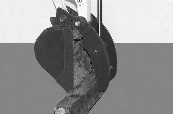
The lifting clamp cylinder must be fully retracted when the machine is being used for excavating.
The lift capacities are reduced by 32 kg (71 lb) if the excavator is equipped with the optional lifting clamp.
If equipped with the switch in the right joystick, move the switch (Item 1) [Figure124] to the right to open the clamp. Move the switch to the left to close the clamp.
Using Auxiliary Hydraulic Pedal To Activate Clamp
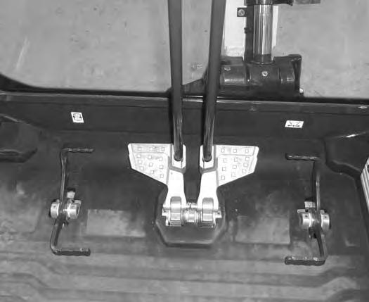
Figure125
If equipped, the auxiliary hydraulic pedal (Item 1), controls the hydraulic clamp. Press the toe (Item 2) of the auxiliary hydraulic pedal to open the clamp. Press the heel (Item 3) [Figure125] of the pedal to close the clamp.
OPERATING PROCEDURE (CONT’D)
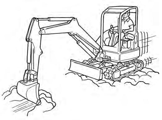
Excavating
Expand the tracks fully. (See TRACK FRAME RETRACTION - EXPANSION on Page 57.)
Lower the blade to increase digging performance.
Figure126
Extend the arm, lower the boom, and open the bucket [Figure126]
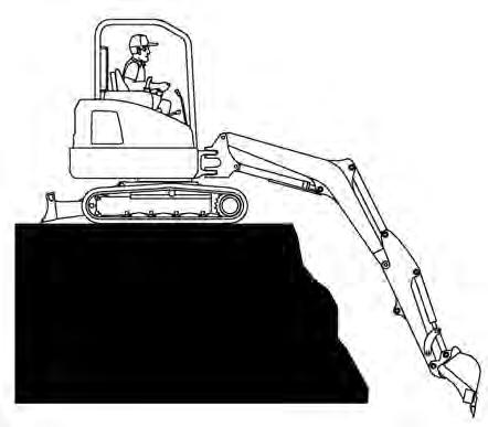
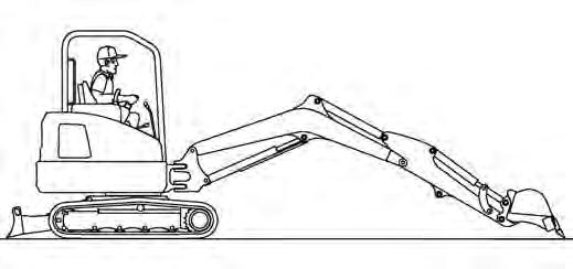
Figure127
Retract the arm, while lowering boom and curling the bucket [Figure127]
Figure128
Raise the boom, retract the arm and curl the bucket [Figure128]
Rotate the upperstructure.
NOTE:Do not allow the bucket teeth to contact the ground when slewing the upperstructure.
Warning
Keep all bystanders 6 m (20 ft) away from equipment when operating. Contact with moving parts, a trench cave-in or flying objects can cause injury or death.
W-2119-0910
Warning
AVOID INJURY OR DEATH
Check area to be excavated for overhead or underground electrical power lines. Keep a safe distance from electrical power lines.
W-2757-0910
OPERATING PROCEDURE (CONT’D)
Excavating (Cont’d)
Figure129
Figure131
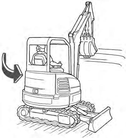
Look in the direction of rotation and make sure there are no bystanders in the work area before rotating the upperstructure [Figure129]
Figure130
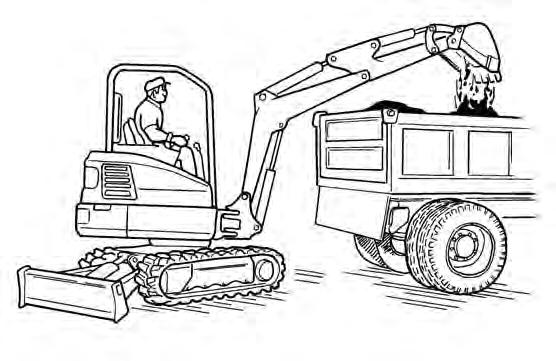
Extend the arm and uncurl the bucket to dump the material into a pile or truck [Figure130]
Important
Avoid operating hydraulics over relief pressure. Failure to do so will overheat hydraulic components. I-2220-0503
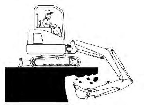
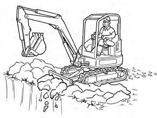
Do not dig under the excavator [Figure131]
Do not use the bucket as a breaker or pile driver. It is better to excavate hard or rocky ground after breaking it with other equipment. This will reduce damage to the excavator.
Do not move the excavator while the bucket is in the ground.
Dig only by moving the boom and arm toward the excavator.
Do not back dig (digging by moving the boom and arm away from the excavator). Damage to the quick coupler and attachments can occur.
OPERATING PROCEDURE (CONT’D)
Boom Swing
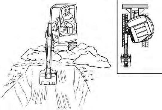
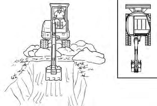
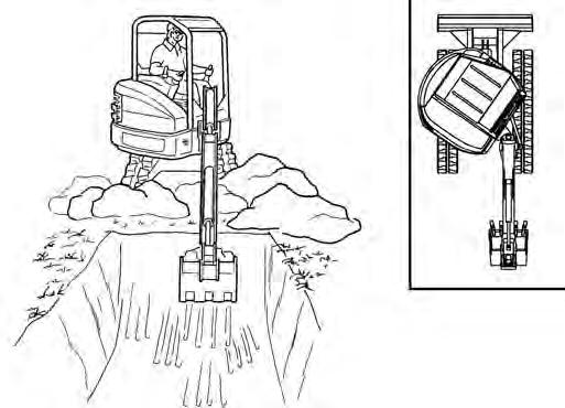
Slew the upperstructure, swing the boom to the right [Figure132], center [Figure133] and left [Figure134] to dig a square hole the width of the machine without repositioning the excavator.
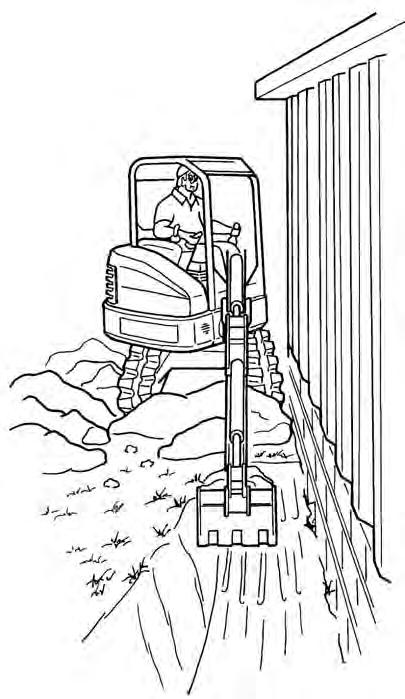
The boom swing allows the operator to offset the boom and dig close to buildings and other structures [Figure135].
OPERATING PROCEDURE (CONT’D)
Backfilling IMPORTANT
Avoid impacting objects with the blade. Damage to blade and undercarriage components may occur.
I-2256-0507
Driving The Excavator
When operating on uneven ground, operate as slow as possible and avoid sudden changes in direction. Avoid traveling over objects such as rocks, trees, stumps, etc.
When working on wet or soft ground, put planks on the ground to provide a solid base to travel on and prevent the excavator from getting stuck.
Use the blade to backfill the trench or hole after excavating [Figure136]
If one or both tracks have become stuck in soft or wet ground, raise one track at a time by turning the upperstructure and pushing the bucket against the ground [Figure137]
Put planks under the tracks and drive the excavator to dry ground.
The bucket can also be used to pull the excavator. Raise the blade, extend the arm and lower the boom. Operate the boom and arm in a digging manner [Figure138]
OPERATING PROCEDURE (CONT’D)
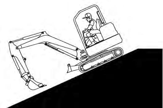
Operating On Slopes
Warning
AVOID INJURY OR DEATH
•Do not travel across or up slopes that are over 15 degrees.
•Do not travel down or back up slopes that exceed 25 degrees.
•Look in the direction of travel.
W-2497-0304
When going down a slope, control the speed with the steering levers and the speed control dial gauge.
Warning
AVOID INJURY OR DEATH
•Avoid steep areas or banks that could break away.
•Keep boom centered and attachments as low as possible when traveling on slopes or in rough conditions. Look in the direction of travel.
•Always fasten seat belt.
W-2498-0304
When going down grades that exceed 15 degrees, put the machine in the position shown, and run the engine slowly [Figure139].
Operate as slow as possible and avoid sudden changes in lever direction.

Avoid traveling over objects such as rocks, trees, stumps, etc.
Stop the machine before moving the upper equipment controls. Never allow the blade to strike a solid object. Damage to the blade or hydraulic cylinder can result.
When traveling up slopes or on side slopes that are 15 degrees or less, position the machine as shown and run the engine slow [Figure140] and [Figure141]