11 minute read
ELECTRICAL SYSTEM Description


Figure187
The excavator has a 12 volt, negative earth electrical system. The electrical system is protected by fuses located under the right side cover of the excavator (Item 1) [Figure187]. The fuses will protect the electrical system when there is an electrical overload. The reason for the overload must be found and corrected before starting the engine again.
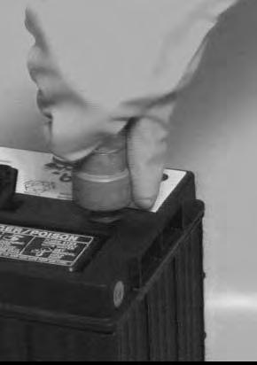
The battery cables must be clean and tight. Check the electrolyte level in the battery. Add distilled water as needed. Remove acid or corrosion from the battery and cables with a sodium bicarbonate and water solution.
Put Battery Saver P/N 6664458 or grease on the battery terminals and cable ends to prevent corrosion.
Warning
AVOID INJURY OR DEATH
Batteries contain acid which burns eyes and skin on contact. Wear goggles, protective clothing and rubber gloves to keep acid off body.
In case of acid contact, wash immediately with water. In case of eye contact get prompt medical attention and wash eye with clean, cool water for at least 15 minutes.
If electrolyte is taken internally drink large quantities of water or milk! DO NOT induce vomiting. Get prompt medical attention.
W-2065-0807
Fuse And Relay Location / Identification
A decal is inside the fuse cover to show location and amp ratings.
Remove the cover to check or replace the fuses and relays.
The location and amperage ratings are shown in [Figure 188].
Always replace fuses using the same type and capacity.
ELECTRICAL SYSTEM (CONT’D)

ELECTRICAL SYSTEM (CONT’D)
Battery Disconnect Switch
When disconnecting or connecting the battery cables, turn the disconnect switch to the OFF position first.
Open the right side cover. (See RIGHT SIDE COVER on Page 110.)
The disconnect switch (Item 1) [Figure189] is located under the right side cover, above the fuel fill cap.
Rotate the switch (Item 1) [Figure189] counterclockwise to turn the switch to the OFF position, clockwise to turn to the ON position (shown in ON position).
NOTE:In the OFF position the shut-off switch key can be removed from the switch. The key is secured to the switch mount with a chain.

ELECTRICAL SYSTEM (CONT’D)
Battery Maintenance
Open the right side cover. (See Opening And Closing on Page 110.)
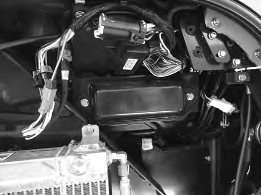
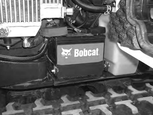
Figure190
The battery (Item 1) [Figure190] is located in the right side upperstructure below the oil cooler.

Figure191
The battery cables must be clean and tight [Figure191] Remove acid or corrosion from the battery and cables using a sodium bicarbonate and water solution. Cover the battery terminals and cable ends with battery saver grease to prevent corrosion.
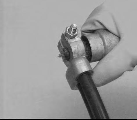
Check for broken or loose connections.
If the battery cables are to be removed for any reason, disconnect the negative (-) cable first. When installing the battery cables, make the last connection the negative (-) cable to the battery.
The original equipment battery is maintenance free. If a replacement battery is installed, check the electrolyte level in the battery.
If the electrolyte level is lower than 13 mm (0.50 in) above the plates, add distilled water only.
Warning
AVOID INJURY OR DEATH
Batteries contain acid which burns eyes and skin on contact. Wear goggles, protective clothing and rubber gloves to keep acid off body.
In case of acid contact, wash immediately with water. In case of eye contact get prompt medical attention and wash eye with clean, cool water for at least 15 minutes.
If electrolyte is taken internally drink large quantities of water or milk! DO NOT induce vomiting. Get prompt medical attention.
W-2065-0807
Using A Booster Battery (Jump Starting)
Important
If jump starting the excavator from a second machine:
When jump starting the excavator from a battery installed in a second machine, make sure the engine is NOT running while using the glow plugs. High voltage spikes from a running machine can burn out the glow plugs.
I-2060-0906
If it is necessary to use a booster battery to start the engine, BE CAREFUL! There must be one person in the operator’s seat and one person to connect and disconnect the battery cables.
Be sure the key switch is OFF. The booster battery must be 12 volt.
Open the tailgate. (See Opening And Closing on Page 109.)
ELECTRICAL SYSTEM (CONT’D)
Using A Booster Battery (Jump Starting) (Cont’d)
NOTE:To access the battery for jump starting, the battery hold-down will need to be removed and the battery moved outward to access the positive battery post.
Figure192
Remove the three bolts (Item 1) and remove the right side lower cover (Item 2) [Figure192]
Open the right side cover. (See Opening And Closing on Page 110.)
Figure193
Remove the two bolts (Item 1) and remove the battery hold-down plate (Item 2) [Figure193]
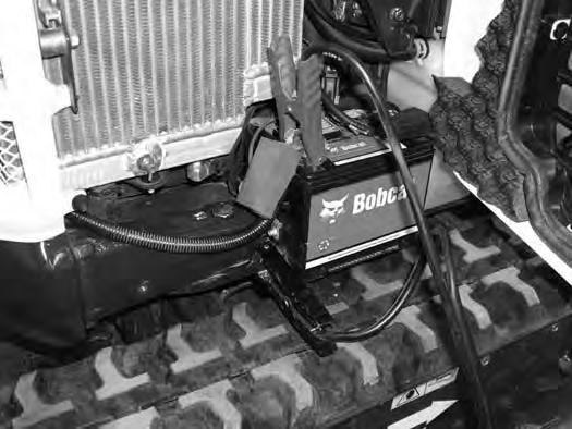
Connect one end of the first cable to the positive (+) terminal of the booster battery. Connect the other end of the same cable to the positive (+) terminal (Item 1) [Figure194] of the excavator battery.
Connect one end of the second cable to the negative (-) terminal of the booster battery. Connect the other end of the same cable to a frame earth point (Item 2) [Figure194]
Start the engine. After the engine has started, remove the negative (-) cable first (Item 1) [Figure194].
Disconnect the cable from the excavator starter (Item 1) [Figure194]
Replace the positive battery cable cover and push the battery in fully. Reinstall the battery hold-down plate (Item 2) and the two bolts (Item 1) [Figure193].
Reinstall the lower right side cover [Figure192]
NOTE:(See Cold Temperature Starting on Page 71.)
Important
Damage to the alternator can occur if:
•Engine is operated with battery cables disconnected.
•Battery cables are connected when using a fast charger or when welding on the excavator. (Remove both cables from the battery.)

•Extra battery cables (booster cables) are connected wrong.
I-2223-0903
ELECTRICAL SYSTEM (CONT’D)
Removing And Installing The Battery

Figure195
Remove the three bolts (Item 1) and remove the right side lower cover (Item 2) [Figure195].
Open the right side cover. (See Opening And Closing on Page 110.)
Turn the battery disconnect switch to the OFF position. (See Battery Disconnect Switch on Page 125.)
Figure196
Remove the two bolts (Item 1) and remove the battery hold-down plate (Item 2) [Figure196].
Slide the battery to the right to access the battery cables.
Disconnect the negative (-) cable (Item 1) [Figure 197] first.
Disconnect the positive (+) cable (Item 2) [Figure 197] Remove the battery. Always clean the terminals and the cable ends, even when installing a new battery.
Position the battery into the battery box. Connect the battery cables. Connect the negative (-) cable (Item 1) [Figure 197] last to prevent sparks. Reinstall the battery post covers and slide the battery in fully.
Tighten the terminal clamp nuts to 7 N•m (5 ft-lb) torque. Install the hold-down plate (Item 2) and the two bolts (Item 1) [Figure196]. Reinstall the lower cover [Figure195]
Turn the battery disconnect switch to the ON position. (See Battery Disconnect Switch on Page 125.)
Warning
AVOID INJURY OR DEATH
Batteries contain acid which burns eyes and skin on contact. Wear goggles, protective clothing and rubber gloves to keep acid off body.
In case of acid contact, wash immediately with water. In case of eye contact get prompt medical attention and wash eye with clean, cool water for at least 15 minutes.
If electrolyte is taken internally drink large quantities of water or milk! DO NOT induce vomiting. Get prompt medical attention.
W-2065-0807
HYDRAULIC SYSTEM Checking And Adding Hydraulic Fluid
Put the machine on a flat level surface.
Retract the arm and bucket cylinders, put the bucket on the ground and lower the blade. Stop the engine.
Open the right side cover. (See Opening And Closing on Page 110.)
Warning
Avoid Injury Or Death
Always clean up spilled fuel or oil. Keep heat, flames, sparks or lighted tobacco away from fuel and oil. Failure to use care around combustibles can cause explosion or fire.
Park the machine in the position shown [Figure198] (The preferred method is to check the hydraulic fluid when it is cold.)
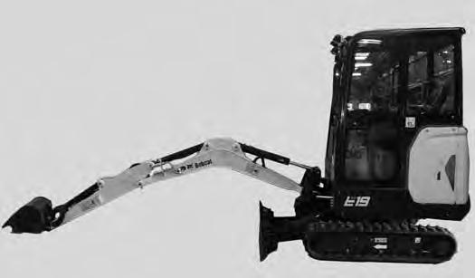
Check the hydraulic fluid level, it must be visible in the sight gauge (Item 1) [Figure198]. The decal on the hydraulic tank shows the correct fill level.

A - Correct Oil Level COLD (Preferred)
B - Correct Oil Level HOT (Optional)
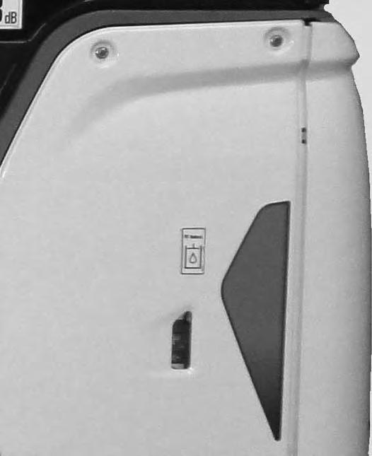
Remove the two screw (Item 1) [Figure199] from the top of the left side cover and remove the cover.
Clean the surface around the reservoir cap (Item 2) [Figure199] and remove the cap.
Check the condition of the fill strainer screen (Item 3) [Figure199]. Clean or replace as necessary.
Be sure the screen is installed before adding fluid.
Add the correct fluid to the reservoir until it is visible in the sight gauge.
Check the cap and clean as necessary. Replace the cap if damaged.
Install the cap.
Close the right side cover and tailgate.
HYDRAULIC SYSTEM (CONT’D)
Hydraulic / Hydrostatic Fluid Chart

Figure200
HYDRAULIC / HYDROSTATIC FLUID RECOMMENDED ISO VISCOSITY GRADE (VG) AND VISCOSITY INDEX (VI)
Removing And Replacing The Hydraulic Filters
Warning
AVOID INJURY OR DEATH
Always clean up spilled fuel or oil. Keep heat, flames, sparks or lighted tobacco away from fuel and oil. Failure to use care around combustibles can cause explosion or fire.
W-2103-0508
Hydraulic Filter
See the service schedule for the correct service interval. (See SERVICE SCHEDULE on Page 103.)
Open the tailgate. (See Opening And Closing on Page 109.)
TEMPERATURE RANGE ANTICIPATED DURING MACHINE USE
[1] VG 100; Minimum VI 130
[2] VG 46; Minimum VI 150
[3] BOBCAT All-Season Fluid
[4] BOBCAT Synthetic Fluid
[5] BOBCAT Biodegradable Hydraulic / Hydrostatic Fluid (Unlike biodegradable fluids that are vegetable based, Bobcat biodegradable fluid is formulated to prevent oxidation and thermal breakdown at operating temperatures.)
Install the oil fill cap.
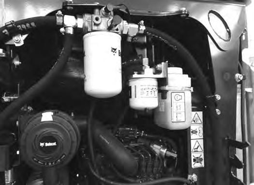
Figure201
P113587
Remove the hydraulic filter (Item 1) [Figure201].
Clean the housing where the filter gasket makes contact. Put clean hydraulic fluid on the gasket. Install the new filter and hand tighten only. Use a genuine Bobcat replacement filter.
Warning
AVOID INJURY OR DEATH
Always clean up spilled fuel or oil. Keep heat, flames, sparks or lighted tobacco away from fuel and oil. Failure to use care around combustibles can cause explosion or fire.
HYDRAULIC SYSTEM (CONT’D)
Removing And Replacing The Hydraulic Fluid
See the service schedule for the correct service interval. (See SERVICE SCHEDULE on Page 103.)
Warning
AVOID INJURY OR DEATH
Diesel fuel or hydraulic fluid under pressure can penetrate skin or eyes, causing serious injury or death. Fluid leaks under pressure may not be visible. Use a piece of cardboard or wood to find leaks. Do not use your bare hand. Wear safety goggles. If fluid enters skin or eyes, get immediate medical attention from a physician familiar with this injury.
W-2072-0807
Retract the arm and bucket cylinders, lower the bucket to the ground. Stop the engine.
Open the tailgate. (See Opening And Closing on Page 109.)
Remove the left side cover [Figure199]
With the engine OFF, loosen the plug (Item 1) [Figure203] on the hydraulic pump. Tighten the plug after a steady stream of hydraulic fluid, free of any air bubbles, drains from the plug. DO NOT RUN THE MACHINE WITH THE PLUG OPEN. Tighten the plug to 30 -34 N•m (22 - 25 ft-lb) torque.
The hydraulic fluid drain plug (Item 1) [Figure202] is located on the hydraulic pump inlet fitting.
Remove the plug (Item 1) [Figure202]
Drain the fluid into a container.
Recycle or dispose of the fluid in an environmentally safe manner.
Install the plug (Item 1) [Figure202]
Add fluid to the reservoir. (See Checking And Adding Hydraulic Fluid on Page 129.)
There is also a plug (Item 1) [Figure204] on the hydraulic cooler for bleeding air. Install a container under the plug and slowly loosen the plug until hydraulic fluid, free of air seeps from the plug. Tighten the plug.


Recycle or dispose of the fluid in an environmentally safe manner.
Start the engine and operate the machine through the hydraulic functions. Stop the engine. Check the fluid level and add as needed.
Spark Arrestor Muffler
Cleaning Procedure
See the SERVICE SCHEDULE for the correct service interval. (See SERVICE SCHEDULE on Page 103.)
Warning
Avoid Injury Or Death
When an engine is running in an enclosed area, fresh air must be added to avoid concentration of exhaust fumes. If the engine is stationary, vent the exhaust outside. Exhaust fumes contain odorless, invisible gases which can kill without warning.
W-2050-0807
Warning
Stop engine and allow the muffler to cool before cleaning the spark chamber. Wear safety goggles. Failure to obey can cause serious injury.
W-2011-1285
Warning
Never use machine in atmosphere with explosive dust or gases or where exhaust can contact flammable material. Failure to obey warnings can cause injury or death.
W-2068-1285
Warning
When the engine is running during service, the steering levers must be in neutral.
Failure to do so can cause injury or death.
Important
This machine is factory equipped with a U.S.D.A. Forestry Service approved spark arrester exhaust system.
The spark arrester muffler, if equipped, must be cleaned to keep it in working condition. The spark arrester muffler must be serviced by dumping the spark chamber every 100 hours of operation.
On some models, the turbocharger functions as the spark arrester and must operate correctly for proper spark arrester function.
If this machine is operated on flammable forest, brush, or grass covered land, it must be equipped with a spark arrester attached to the exhaust system and maintained in working order. Failure to do so will be in violation of California State Law, Section 4442. PRC. Refer to local laws and regulations for spark arrester requirements.
I-2284-0111
Do not operate the excavator with a defective exhaust system.
Stop the engine. Open the tailgate. (See TAILGATE on Page 109.)
Remove the left side cover.
W-2203-0595
SPARK ARRESTOR MUFFLER Cleaning Procedure (Cont’d)
Figure205
P113596
Remove the plug (Item 1) [Figure205] from the bottom of the muffler.
Start the engine and run for about 10 seconds while a second person, wearing safety glasses, holds a piece of wood over the outlet of the muffler. The carbon deposits will be forced out of the muffler plug hole (Item 1)
[Figure205]
Stop the engine. Install and tighten the plug. Close the tailgate.
Track Tension
Checking Tension
NOTE:The wear of the pins and bushings on the undercarriage vary with the working conditions and the different types of soil conditions. It is necessary to inspect track tension and maintain the correct tension. See service schedule for the correct service interval. (See SERVICE SCHEDULE on Page 103.)
Raise the side of the machine (approximately 102 mm [4 in]) using the boom and arm.
Warning
AVOID INJURY
Keep fingers and hands out of pinch points when checking the track tension.
W-2142-0903
Track Clearance
8,3 - 13,5 mm
(0.33 - 0.53 in)
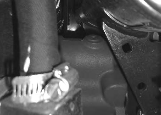
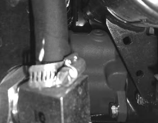
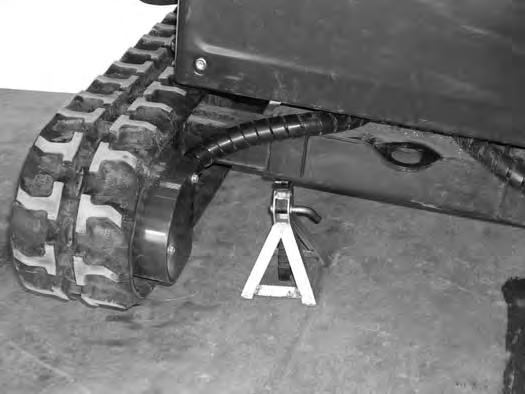
Raise the blade fully and install jackstands under the blade and track frame (Item 1) [Figure206] and [Figure207]. Raise the boom until all machine weight is on the jackstands.

Stop the engine.
8,3 - 13,5 mm (0.33 - 0.53 in)
Measure the clearance at either middle track roller. Do not get fingers into pinch points between the track and the track roller. Use a bolt or a dowel of the appropriate size to check the gap between the contact edge of the roller and the top edge of the track guide [Figure208] and [Figure209]
Track Clearance 8,3 - 13,5 mm (0.33 - 0.53 in)

TRACK TENSION (CONT’D)
Adjusting Tension
Figure210
Decrease Track Tension
Warning
AVOID INJURY OR DEATH
If grease fitting is removed before pressure is released, the fitting can come off with great force and cause serious injury or death.

W-2490-0104
Pressure must be released from the grease cylinder to decrease track tension.
Loosen the bleed fitting (NOT the grease fitting) (Item 2) [Figure210] and release pressure until the track tension is correct.
Loosen the access cover bolts and pivot the access cover open [Figure210].
Increase Track Tension
Add grease to the fitting (Item 1) [Figure210] until the track tension is correct.
NOTE:DO NOT loosen the bleed fitting (Item 2) [Figure210] for more than eight turns.
Tighten the bleed fitting to 80 - 100 N•m (59 - 74 ft-lb) torque.
Pivot the access cover closed and tighten the access cover bolts.
Raise the machine and remove the jackstands.
Repeat the procedure for the other side.
Dispose of grease in an environmentally safe manner.