3 minute read
TRAVEL MOTOR


Checking And Adding Oil
Figure211
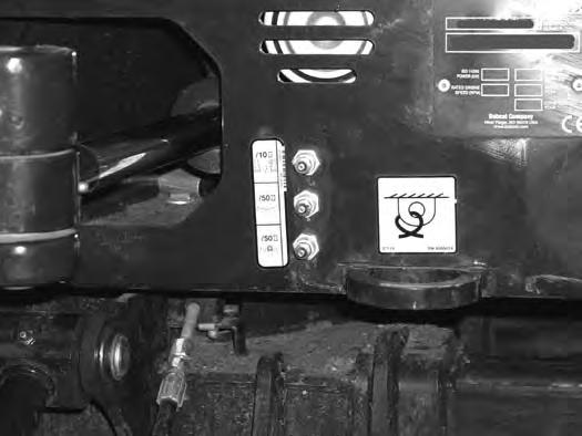
Park the excavator on a level surface with the plugs (Items 1 and 2) [Figure211] in the position as shown.
Remove the plug (Item 1) [Figure211]. The fluid level must be at the bottom edge of the hole.
Add lubricant (SAE 80W90) through the hole if the fluid level is low.
Removing And Replacing Oil
See the service schedule for the correct service interval. (See SERVICE SCHEDULE on Page 103.)
Park the excavator on a level surface with plugs (Items 1 and 2) [Figure211] in the position shown. Remove both plugs and drain the lubricant into a container.
Warning
AVOID INJURY OR DEATH
Always clean up spilled fuel or oil. Keep heat, flames, sparks or lighted tobacco away from fuel and oil. Failure to use care around combustibles can cause explosion or fire.
Install the bottom plug (Item 2) [Figure211]. Add fluid through the center plug hole until the fluid level is at the bottom edge of the hole.
Install the plug (Item 1) [Figure211].
Alternator And Fan Belt

Belt Adjustment
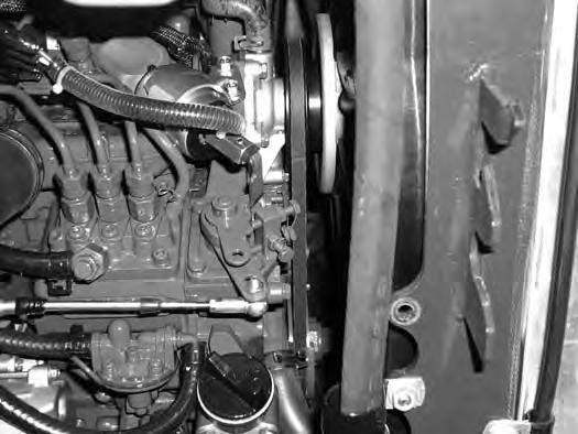
Stop the engine and open the tailgate. (See Opening And Closing on Page 109.)
Remove the two bolts (Item 1) and reposition the belt guard (Item 2) [Figure212] out of the way.
Measure the belt (Item 3) [Figure212] tension at the middle of the belt span.
If a belt tension tool is available, the correct belt tension is; (new belt = 272 - 292 N [61 - 65 lbf] or used belt = 233 - 252 N [53 - 57 lbf]) tension.
If a belt tension tool is not available, the correct belt tension is; 8,0 mm (5/16 in) movement at the middle of the belt span with 66 N (15 lbf) of force.
Reinstall the belt guard (Item 2) and the two bolts (Item 1) [Figure212]
Remove the four plastic rivets (Item 1) [Figure213] and remove the toolbox from under the seat for access to the alternator adjusting bolts.
If the belt tension is not correct, loosen the bolt and nut (Item 2) and the bolt (Item 3) [Figure213] until the alternator can be rotated for adjustment.

Adjust belt tension to correct specifications [Figure212]
Tighten the mounting and adjustment bolts. Recheck the belt tension to confirm it did not change while tightening the alternator bolts.
Reinstall the belt guard (Item 2) [Figure212]
Close the tailgate.
Belt Replacement
Loosen the bolt and nut (Item 2) and the bolt (Item 3) [Figure213] until the alternator can be moved toward the engine.
Remove the old belt and install a new belt.
Adjust belt tension to correct specifications [Figure212].
Tighten the mounting and adjustment bolts. Recheck the belt tension to confirm it did not change while tightening the alternator bolts.
Reinstall the belt guard (Item 2) [Figure212]
Close the tailgate.
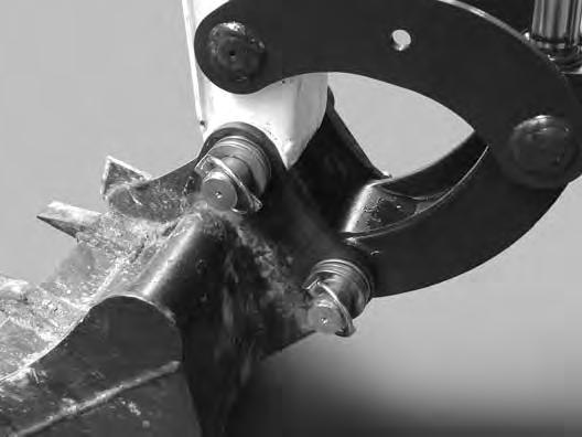
Quick Coupler
Bucket Link And Attachment Coupler Inspection And Maintenance
Figure214
Inspect the bucket link (Item 1) for wear or damage. Inspect the attachment pins (Item 2) [Figure214] for wear or damage.
Repair or replace damaged parts.
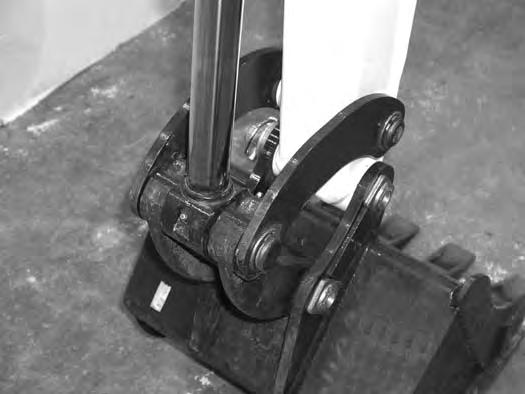
Track Roller And Idler Lubrication
Procedure
The track rollers and idlers require no maintenance. The bearings are a sealed design.

Inspect the quick coupler for wear or damage (if equipped). Inspect the quick coupler pins (Item 1) and the hooks (Item 2) [Figure215] (on the attachment) for wear or damage
Repair or replace damaged parts.
Lubrication Of The Hydraulic Excavator

Lubrication Locations
Lubricate the excavator as specified in the service schedule for the best performance of the machine. (See SERVICE SCHEDULE on Page 103.)
Always use a good quality lithium based multipurpose grease when lubricating the machine. Apply the lubricant until extra grease shows.
Lubricate the following locations on the excavator EVERY 8 - 10 HOURS:
LUBRICATION OF THE HYDRAULIC EXCAVATOR (CONT’D)
Lubrication Locations (Cont’d)
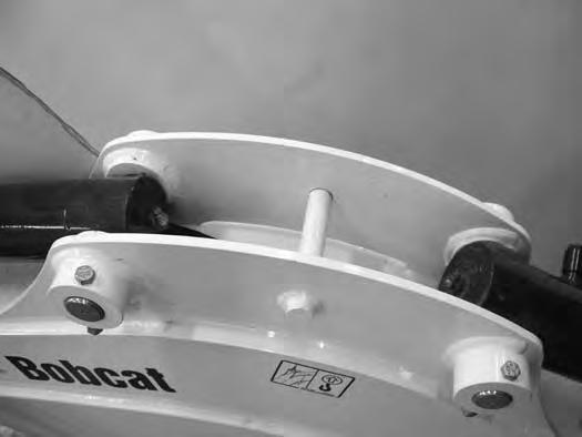
Figure219
8.Boom Cylinder Base End (1) [Figure219]
9.Arm Cylinder Base End (1) [Figure219]
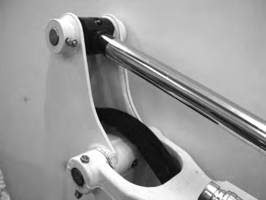
12.Bucket Cylinder Base End (1) [Figure221]
10.Arm Cylinder Rod End (1) [Figure220]
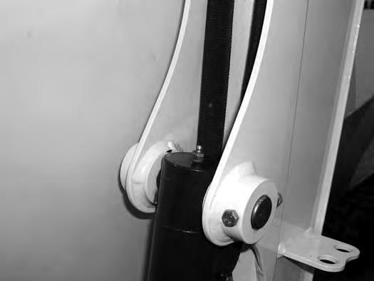
11.Arm Pivot (1) [Figure220]
13.Bucket Cylinder Rod End (1) [Figure222]
14.Bucket Link Pin (1) [Figure222]
15.Bucket Pivot (2) [Figure222]
16.Bucket Link (2) [Figure222]
LUBRICATION OF THE HYDRAULIC EXCAVATOR (CONT’D)
Lubrication Locations (Cont’d)
Figure223
17.Cab Door hinges (3) [Figure223] (If Equipped)

Figure224
18.Boom Swing Cylinder Base (1) [Figure224]
Lubricate the following locations on the hydraulic excavator EVERY 50 HOURS:
19.Slew Circle (1) [Figure224]
20.Slew Pinion (1) [Figure224]. (Install three to four pumps of grease then rotate the upperstructure 90°. Install three to four pumps of grease and again rotate the upperstructure 90°. Repeat this until the slew pinion has been greased at four positions.)