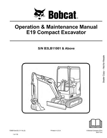
4 minute read
TRACK FRAME RETRACTION - EXPANSION Operation


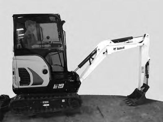
The excavator can be operated with the track frame retracted for transportation on a trailer or to access narrow areas [Figure55]

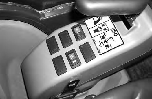
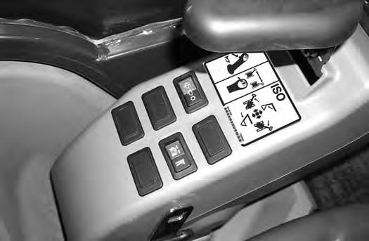
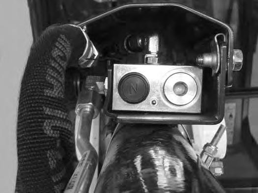
Put the Blade / Track Retraction - Expansion Switch (Item 1) [Figure57] to the right in the Blade position.
With the boom and arm positioned over the blade, lower the blade until the track is raised 100 - 150 mm (4.006.00 in) off the ground [Figure57]
Rotate the upperstructure 180 degrees.
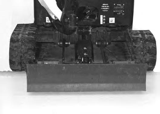
Expand the track frame for increased digging performance [Figure56]
Important
To prevent wear and damage to the track, always lift the excavator before expanding or retracting the track frame.
Lower the boom and arm to raise the rear of the excavator until the track is 100 - 150 mm (4.00 - 6.00 in) off the ground [Figure58].
TRACK FRAME RETRACTION - EXPANSION (CONT’D) Operation (Cont’d)
Figure59
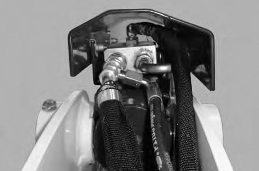
Push the Blade / Track Retraction - Expansion Switch (Item 1) [Figure59] to the Track Retraction - Expansion position.
Important
To prevent wear and damage to the track, always lift the excavator before expanding or retracting the track frame.
I-2193-0599
NOTE:Always return the Blade / Track RetractionExpansion Switch (Item 1) [Figure61] to the Blade position during operation so that the track does not move when using the Blade / Track Retraction - Expansion Lever.
Raise the boom and arm to lower the rear of the excavator to the ground.
Rotate the upperstructure 180 degrees.
Raise the blade until the tracks are on the ground.
Blade Expansion
Figure62
Push the Blade / Track Retraction - Expansion Lever (Item 1) [Figure60] forward to expand the track frame. Hold the lever forward until the track frame is fully expanded.
Pull the Blade / Track Retraction - Expansion Lever [Figure60] back to retract the track frame. Hold the lever back until the track frame is fully retracted. The track frame must be either in the fully expanded or fully retracted position when in use.
Raise the blade sightly and place a block under the blade. Lower the blade fully.
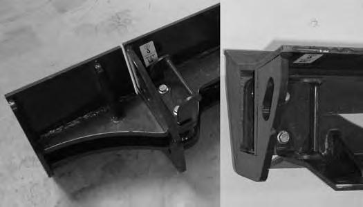
Remove the blade retainer pin assembly (Item 1) [Figure62].
Remove and reposition the blade extension (Item 2) [Figure62] to the outside blade position.
Reinstall the blade retainer pin assembly (Item 3) [Figure62]
NOTE:Always operate the machine with the tracks fully expanded or fully retracted.
BOOM SWING Operation
WHEN EQUIPPED WITH JOYSTICK SWITCH (ITEM 1)
WHEN EQUIPPED WITH BOOM SWING PEDAL (ITEM
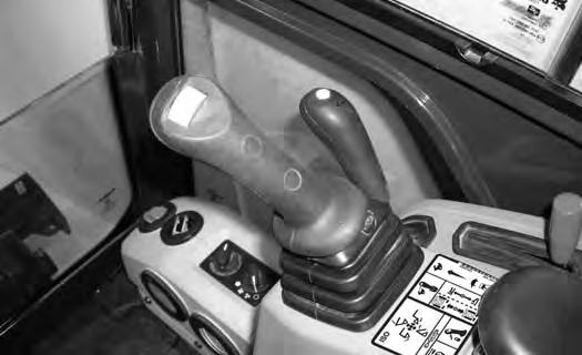
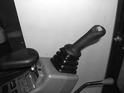
When equipped with Joystick Switch (Item 1) [Figure63]:
The boom swing switch (Item 1) [Figure63] (if equipped) on the left control lever (joystick) controls boom swing. Move the switch to the left to swing the boom to the left. Move the switch to the right to swing the boom to the right.
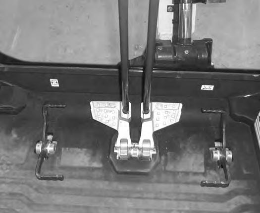
When equipped with Boom Swing Pedal (Item 2) [Figure63]:
The boom swing pedal (Item 2) (if equipped) controls boom swing. Press the toe (Item 3) of the pedal to swing the boom to the left. Press the heel (Item 4) [Figure63] of the pedal to swing the boom to the right.
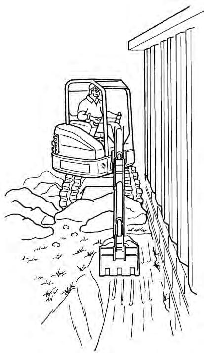
NOTE:The purpose of the boom swing is to offset the boom with respect to the upperstructure for digging close to a structure [Figure64].
BOOM LOAD HOLDING VALVE
Description
The boom load holding valve (if equipped) will hold the boom in it’s current position in the event of hydraulic pressure loss.
Warning
AVOID INJURY OR DEATH
Do Not work or stand under raised work equipment or attachment.
Lowering Boom With Load Holding Valve

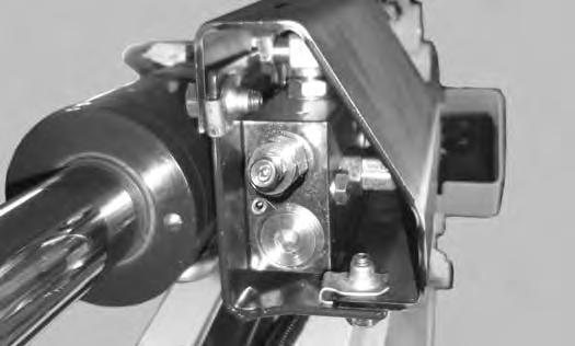
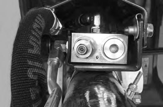
NOTE:DO NOT remove or adjust the port relief valve (Item 1) [Figure66] (that the drain hose is connected to). If the port relief valve have been tampered with, see your Bobcat dealer for service.
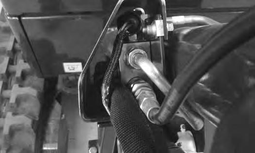
If the excavator is equipped with a boom load holding valve (Item 1) [Figure65], it will be attached to the boom cylinder at the rod end.
NOTE:DO NOT remove or adjust the two port relief valves (Item 2) [Figure65]. If the port relief valves have been tampered with, see your Bobcat dealer for service.

Warning
AVOID BURNS
Hydraulic fluid, tubes, fittings and quick couplers can get hot when running machine and attachments. Be careful when connecting and disconnecting quick couplers.
BOOM LOAD HOLDING VALVE (CONT’D)
Lowering Boom With Load Holding Valve (Cont’d)
Figure68
Lowering procedures:
With base end hose failure, or with rod end hose failure and NO accumulator pressure:
NOTE:If the relief valve must me adjusted to lower the boom, the relief valve must be replaced. It can not be reset back to the factory setting.
Loosen the jam nut (Item 1). Install a hex wrench into the valve screw (Item 2) [Figure68] and slowly rotate the screw clockwise and allow the boom to lower to the ground.
Replace the relief valve [Figure68]. See your Bobcat dealer for service parts.
With rod end hose failure - with accumulator pressure:
Place a container under the valve and hose end to contain hydraulic fluid. Enter the excavator and turn the key switch to the ON position or press the ENTER CODE Button (Keyless Panel), but do not start the engine. Slowly move the joystick boom lower function and allow the boom to lower to the ground.
Loss of hydraulic pressure:
Use the same procedure as: With base end hose failure, or with rod end hose failure and NO accumulator pressure
ARM LOAD HOLDING VALVE
Description
The arm load holding valve (if equipped) will hold the arm in it’s current position in the event of hydraulic pressure loss.
Warning
AVOID INJURY OR DEATH
Do Not work or stand under raised work equipment or attachment.
Lowering Arm With Load Holding Valve
NOTE:DO NOT remove or adjust the port relief valve (Item 1) [Figure70] (that the drain hose is connected to). If the port relief valve have been tampered with, see your Bobcat dealer for service.
If the excavator is equipped with arm load holding valve (Item 1) [Figure69], it will be attached to the arm cylinder base end as shown.
Warning
AVOID BURNS
Hydraulic fluid, tubes, fittings and quick couplers can get hot when running machine and attachments. Be careful when connecting and disconnecting quick couplers.
W-2220-0396
ARM LOAD HOLDING VALVE (CONT’D)
Lowering Arm With Load Holding Valve (Cont’d)
Figure72
Lowering procedures:
With base end hose failure, or with rod end hose failure and NO accumulator pressure:
NOTE:If the relief valve must me adjusted to lower the boom, the relief valve must be replaced. It can not be reset back to the factory setting.
Loosen the jam nut (Item 1). Install a hex wrench into the valve screw (Item 2) [Figure72] and slowly rotate the screw clockwise and allow the arm to lower to the ground.
Replace the relief valve [Figure72]. See your Bobcat dealer for service parts.
With rod end hose failure - with accumulator pressure:
Place a container under the valve and hose end to contain hydraulic fluid. Enter the excavator and turn the key switch to the ON position or press the ENTER CODE Button (Keyless Panel), but do not start the engine. Move the joystick arm retract function to slowly lower the arm.
Loss of hydraulic pressure:
Use the same procedure as: With base end hose failure, or with rod end hose failure and NO accumulator pressure