3. Attach the choke shaft lever (Item 15) to the choke shaft with its hex nut (Item 16). Position the lever as marked at time of disassembly. Securely tighten the nut.
Adjustment
Regulator
4. With the carburetor inverted, replace the pipe plug (Item 21), adjustment screw locknut (Item 12) and adjustment screw (Item 13). Turn the adjustment screw in against its seat, then back it out two turns. 5. With the flange of the carburetor up, place the venturi (Item 4) into the throttle bore with the side hole in line with the screw hole in the main body and secure the venturi with its retaining screw (Item 11). 6. Place the throttle shaft seals (Item 3) into the seal retainers (Item 2) and assemble the seals and retainers into the counterbores of the main body. 7. Insert the throttle shaft and lever (Item 10) through the seals so the throttle stop screw is in contact with the stop pin when the throttle plate is in closed position. Attach the throttle plate (Item 6) to the shaft. Leave the screws loose. Align the throttle plate to the match marks. Close the throttle and align the plate for best closing. Tighten the screws.
Fuel Inlet
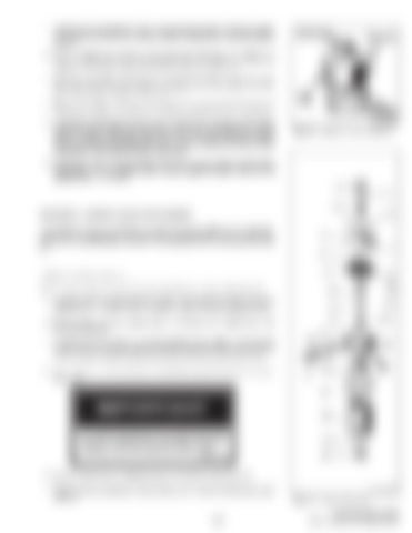
Vaporizer Heat Exchanger A–01820
Fig. 72
Vaporizer – Primary Regulator
8. Place the spring on the idle needle valve (Item 8) and install the idle needle and spring. Turn the needle valve in lightly against its seat. Back out the needle valve 1–1/4 turns. 2 3 4 5
VAPORIZER – PRIMARY REGULATOR SERVICE The vaporizer (Fig. 72) consists of a high pressure regulator and vaporizer combined into a single unit. The high pressure regulator reduces LPG fuel tank pressure to a uniform outlet pressure. The vaporizer section vaporizes the liquid gas.
6 7
8 9
To disassemble the vaporizer: Refer to figure 73 for parts identification and follow the steps outlined below.
19
1. To remove the corrugated heat exchanger, clamp the vaporizer in a vise and remove the 1–1/4 inch brass nut (Item 24) with a thin wall socket wrench.
17 15
2. Remove the inlet orifice retainer (Item 11) and aluminum washer (Item 12) from the inlet bore. 3. Loosen the locknut (Item 3) on the adjusting screw (Item 2) and turn the screw all the way down to depress the inlet valve seat. The valve seat in its normal position interferes with the removal of the inlet orifice (Item 13). 4. Turn a 1/4 inch –20 screw into the inlet orifice block and remove the block (Item 13).
10
12
20 18 16
14
13 11 21
22 The spring loaded inlet valve seat must be fully pressed in during this operation to prevent damage to both the seat and orifice block.
23
I–2147–1297
24
5. Remove the pressure adjusting screw (Item 2) and spring (Item 4). 6. Remove the six diaphragm cover screws (Item 5) and the diaphragm cover (Item 6). –33–
B–01225
Fig. 73
Vaporizer Breakdown
444, 500, 600 Loader Service Manual Supplement

