To check the condition of the hydraulic pump: 1. Remove the hoses from the auxiliary tubelines and connect them to the tilt cylinder tubelines at the rear of the machine. Connect the hose from the inlet port of the tester to the rear tilt tubeline. Connect the hose from the outlet port of the tester to the front tilt tubeline (Fig. 7). 2. Place a stopper (0.312 x 1 inch long carriage bolt) between the clutch lubrication manifold tee and the master relief valve tubeline fitting (Fig. 7). 3. Be sure the pressure control valve knob on the tester is turned out (counterclockwise) as far as it will go. 4. Start the engine and run it at low idle. 5. Press the heel of the tilt control pedal down and hold it (Fig. 7). 6. Slowly turn the pressure control valve knob on the tester clockwise to increase the system pressure.
You now have no relief valve in the system. Closing the pressure control valve knob too fast may cause the hydraulic pump or the tester pressure cap to fall because of excessive pressure. Increase the pressure only to 200 PSI. Do not try to check the maximum pump output. W–2279–0198
If you get a higher pressure reading (above 1700 PSI) with the master relief valve blocked, the relief valve setting was too low. If you get the same reading as before (below 1700 PSI) one of the following is occurring:
1 2
1. The cartridge relief setting in the lift and auxiliary control valve is too low. 2. The hydraulic pump is worn and not delivering as much oil as it should.
3 4
To check the pressure setting of the cartridge relief in the lift and auxiliary control valve, follow this procedure:
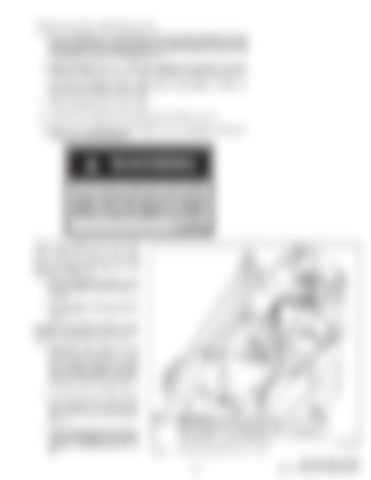
Aux. Lines
1. Reconnect the tester to the auxiliary tubelines at the rear of the machine. Connect a hose from the rear auxiliary line to the outlet port of the tester. Connect a hose from the front auxiliary line to the inlet port of the tester (Fig. 8). 2. Leave the stopper (0.312 x 1 inch long carriage bolt) between the clutch lubrication manifold tee and the master relief valve tubeline fitting. 3. Be sure the pressure control valve knob on the tester is turned out (counter clockwise) as far as it will go.
Aux. Pedal
Ref. 1 2 3 4 Fig. 8
Description Qty. Reducer, 3/4” NPT (M) x 1/2” NPT (F) 2 Straight Adapter, 1/2” NPT (M) x 1/2” 37° Flare (M) 2 Hose, 100R1, 1/2” 37° Flare (M) x 1/2” 37° Flare (FS) 2 Carriage Screw, 5/16” x 1” (plated) 1
A–01112
Checking Cartridge Relief Pressure Setting
–5–
444, 500, 600 Loader Service Manual Supplement

