9 minute read
ELECTRICAL SYSTEM

from Bobcat 442 Compact Excavator Operation & Maintenance Manual SN ADBR11001 & Above - PDF DOWNLOAD

Description
Warning
AVOID INJURY OR DEATH
Batteries contain acid which burns eyes and skin on contact. Wear goggles, protective clothing and rubber gloves to keep acid off body.
In case of acid contact, wash immediately with water. In case of eye contact get prompt medical attention and wash eye with clean, cool water for at least 15 minutes.
If electrolyte is taken internally drink large quantities of water or milk! DO NOT induce vomiting. Get prompt medical attention.
The excavator has a 12 volt, negative ground electrical system. The electrical system is protected by fuses located in the right console and beside the battery [Figure PM-36] & [Figure PM-37]. The fuses will protect the electrical system when there is an electrical overload. The reason for the overload must be found before starting the engine again.

The battery cables must be clean and tight. Check the electrolyte level in the battery. Add distilled water as needed. Remove acid or corrosion from the battery and cables with a sodium bicarbonate and water solution.
Put Battery Saver P/N 6664458 or grease on the battery terminals and cable ends to prevent corrosion.
ELECTRICAL SYSTEM (CONT’D)
Fuse And Relay Location
To check or replace the fuses in the right console, remove the screws (Item 1) and remove the cover (Item 2) [Figure

1 Key switch, interior light, security ignition (If equipped)
10A
2Aux power outlet, radio, heater15A
3Rotating beacon (If equipped)10A
4Flood light (Front)15S
5Flood light (Back)15A
6Fuel pump15A
7Horn, panel light, security ignition (If equipped)
10A
8Heater fan15A
9Wiper/washer, radio15A
10Hyd. oil level, hyd functions, overload warning 5A
11Travel pressure switch5A
12Main hyd. system5A
13Left and right joystick5A
14Air conditioning box10A
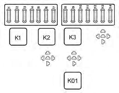
K1Flood light (Front)Relay
K2Flood light (Rear)Relay
K3OpenRelay
K01Switch powerRelay
Always replace fuses with the same type and capacity.
ELECTRICAL SYSTEM (CONT’D)
Fuse And Relay Location (Cont’d)
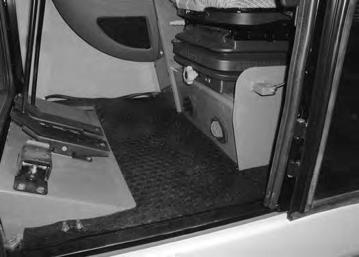
To check or replace fuses beside the battery, pull up on and remove the floor mat (Item 1) [Figure PM-41]


REF. DESCRIPTION AMPERAGE
Always replace fuses with the same type and capacity.
ELECTRICAL SYSTEM (CONT’D)
Fuse And Relay Location (Cont’d)
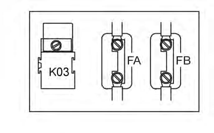
Open the right side cover.
Always replace relays with the same type and capacity.
Using A Booster Battery (Jump Starting)
If it is necessary to use a booster battery to start the engine, BE CAREFUL! There must be one person in the operator's seat and one person to connect and disconnect the battery cables.

Be sure the key switch is OFF. The booster battery must be 12 volt.

ELECTRICAL SYSTEM (CONT’D)
Using a Booster Battery (Jump Starting) (Cont’d)
Warning
AVOID INJURY OR DEATH
Batteries contain acid which burns eyes and skin on contact. Wear goggles, protective clothing and rubber gloves to keep acid off body.
In case of acid contact, wash immediately with water. In case of eye contact get prompt medical attention and wash eye with clean, cool water for at least 15 minutes.
If electrolyte is taken internally drink large quantities of water or milk! DO NOT induce vomiting. Get prompt medical attention.
W-2065-0807
Warning
AVOID INJURY OR DEATH
Keep arcs, sparks flames and lighted tobacco away from batteries. When jumping from booster battery make final connection (negative) at machine frame.
Do not jump start or charge a frozen or damaged battery. Warm battery to 60°F (16°C) before connecting to a charger. Unplug charger before connecting or disconnecting cables to battery. Never lean over battery while boosting, testing or charging.
Battery gas can explode and cause serious injury.

W-2066-0705
Connect one end of the first cable to the positive (+) terminal of the booster battery. Connect the other end of the same cable to the positive (+) terminal (Item 1) [Figure PM-49] of the excavator battery.
Connect the end of the second cable to the negative (-) terminal of the booster battery. Connect the other end of the same cable to the excavator frame (Item 2) [Figure PM-49] (away from the battery).
NOTE: (See Cold Temperature Starting Procedure on Page OI-32.)
Start the engine. After the engine has started, remove the ground (-) cable first (Item 2) [Figure PM-49]
Disconnect the cable from the excavator battery (Item 1) [Figure PM-49].
ELECTRICAL SYSTEM (CONT’D)
Removing And Installing Battery
Important
If jump starting the excavator from a second machine:
When jump starting the excavator from a battery installed in a second machine, make sure the engine is NOT running while using the glow plugs. High voltage spikes from a running machine can burn out the glow plugs.
I-2060-0906
Important
Damage to the alternator can occur if:
•Engine is operated with battery cables disconnected.
•Battery cables are connected when using a fast charger or when welding on the loader. (Remove both cables from the battery.)
•Extra battery cables (booster cables) are connected wrong.
I-2023-1285
Warning
AVOID INJURY OR DEATH
Batteries contain acid which burns eyes and skin on contact. Wear goggles, protective clothing and rubber gloves to keep acid off body.
In case of acid contact, wash immediately with water. In case of eye contact get prompt medical attention and wash eye with clean, cool water for at least 15 minutes.
If electrolyte is taken internally drink large quantities of water or milk! DO NOT induce vomiting. Get prompt medical attention.
W-2065-0807
ELECTRICAL SYSTEM (CONT’D)
Removing And Installing Battery (Cont’d)

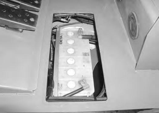
Figure PM-52
Warning
AVOID INJURY OR DEATH
Batteries contain acid which burns eyes and skin on contact. Wear goggles, protective clothing and rubber gloves to keep acid off body.
In case of acid contact, wash immediately with water. In case of eye contact get prompt medical attention and wash eye with clean, cool water for at least 15 minutes.
If electrolyte is taken internally drink large quantities of water or milk! DO NOT induce vomiting. Get prompt medical attention.
W-2065-0807
Disconnect the negative (-) cable (Item 1) [Figure PM52] first.
Disconnect the positive (+) cable (Item 2) [Figure PM52].
Figure PM-53
Remove the nuts (Item 1) and remove the hold down clamp (Item 2) [Figure PM-53].
Remove the battery.
Always clean the terminals and the cable ends, even when installing a new battery.
Install the battery. Install the hold down clamp and tighten the bolts.
Connect the battery cables. Connect the negative (-) cable (Item 1) [Figure PM-52] last to prevent sparks.
Alternator Belt
Adjusting Belt Tension
Check the alternator belt deflection at the mid span of the belt between the crankshaft pulley and alternator pulley.

Apply approximately 33 lb. (45 mm) force to the belt. The belt should deflect 0.40 in. (10 mm).
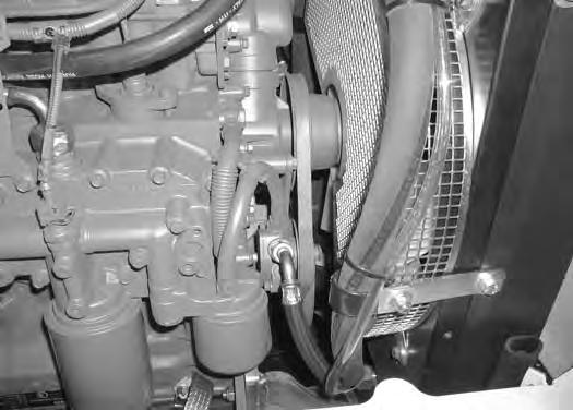
Fan Belt
Adjusting Belt Tension
Tighten the bolts.
Check the fan belt (Item 1) [Figure PM-56] deflection mid span of the belt between the crankshaft pulley and the fan pulley.
Apply approximately 33 lb. (45 N) of force to the belt. The belt should deflect 0.40 in. (10 mm).
Tighten the bolts.
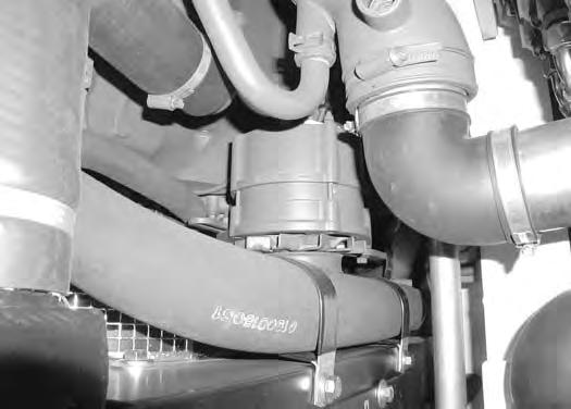
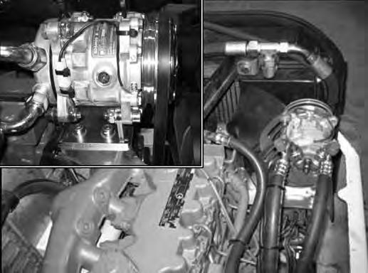
Air Conditioning Compressor Belt
Adjusting Belt Tension
Figure PM-58
Check the air conditioning compressor belt deflection mid span of the belt between the crankshaft pulley and the compressor pulley (Item 1) [Figure PM-58]
Apply approximately 33 lb. (45 mm) force to the belt. The belt should deflect 0.40 in. (10 mm).
Loosen the bolts (Item 2) [Figure PM-58] and rotate the compressor until the belt is correctly tensioned.
Tighten the bolts.
HYDRAULIC SYSTEM Checking And Adding Hydraulic Oil
Put the machine on a flat level surface.
Retract the arm and bucket cylinders, put the bucket on the ground and raise the blade. Stop the engine. Open the rear cover.
Check the hydraulic fluid level, it must be visible in the sight gauge (Item 1) [Figure PM-59]
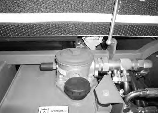
Clean the surface around the reservoir (breather) cap and remove the cap from the reservoir (Item 1) [Figure PM-60]
Add the correct oil to the reservoir until it is visible in the sight gauge. (See Capacities on Page SPEC-6.)
Check the breather cap and clean as necessary. Replace the cap if damaged. Install the reservoir cap. Close the rear cover.
HYDRAULIC SYSTEM (CONT’D)
Replacing The Hydraulic Oil
See Service Schedule for the correct service interval. (See SERVICE SCHEDULE on Page PM-5.)
Retract the arm and bucket cylinders, lower the bucket to the ground. Stop the engine.

Open the rear cover.

Figure PM-61
Remove the cap (Item 1) [Figure PM-61] from the hydraulic reservoir drain.
Figure PM-62
Install the drain hose (Item 1) [Figure PM-62] on the hydraulic reservoir. Tighten the hose until oil starts to drain from the reservoir.
Drain the fluid into a container.
Recycle or dispose of the fluid in an environmentally safe manner.
Remove the drain hose and install the cap on the hydraulic reservoir.
Add fluid to the reservoir. (See Capacities on Page SPEC-6.)
Run the machine through the hydraulic functions. Stop the engine. Check the fluid level and add as needed.
Warning
Avoid Injury Or Death
Always clean up spilled fuel or oil. Keep heat, flames, sparks or lighted tobacco away from fuel and oil. Failure to use care around combustibles can cause explosion or fire.
W-2103-0508
Warning
Avoid Injury Or Death
Diesel fuel or hydraulic fluid under pressure can penetrate skin or eyes, causing serious injury or death. Fluid leaks under pressure may not be visible. Use a piece of cardboard or wood to find leaks. Do not use your bare hand. Wear safety goggles. If fluid enters skin or eyes, get immediate medical attention from a physician familiar with this injury.
HYDRAULIC SYSTEM (CONT’D)
Hydraulic Filter Removal
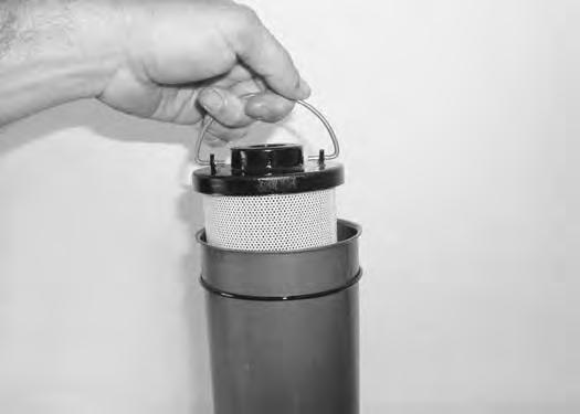

See Service Schedule for the correct service interval. (See SERVICE SCHEDULE on Page PM-5.)

HYDRAULIC SYSTEM (CONT’D)
Hydraulic Filter Installation
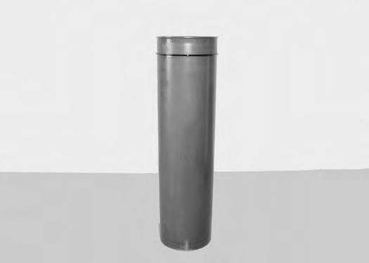
Clean the filter bowl in clean solvent and dry with compressed air.

HYDRAULIC SYSTEM (CONT’D)


Hydraulic Filter Installation (Cont’d)
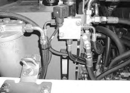
Diagnostic Couplers
Open the rear cover and right side cover.

TRACK TENSION
Rubber Track Clearance
NOTE: The wear of the pins and bushings on the undercarriage vary with the working conditions and the different types of soil conditions. It is necessary to inspect track tension and maintain the correct tension. For the correct service interval (See SERVICE SCHEDULE on Page PM-5.)

NOTE: On new excavators or on excavators with new rubber tracks installed, check and adjust as needed the rubber track clearance two to three times on the first day of operation.
Warning
AVOID INJURY
Keep fingers and hands out of pinch points when checking the track tension.
Raise one side of the machine (approximately four inches) using the boom and arm.

Raise the blade fully and install jackstands (Item 1) [Figure PM-74] & [Figure PM-75] under the blade and track frame. Lower the boom until all machine weight is on the jackstands.
Stop the engine.
TRACK TENSION (CONT’D)
Rubber Track Clearance (Cont'd)
Measure the track sag at the third roller (Item 1) [Figure PM-76] from the front of the track frame. Do not get fingers in pinch points between the track and track roller. Use a bolt or dowel of the appropriate size to check the gap between the contact edge of the roller and the top edge of the track guide lug [Figure PM-77]
Rubber track clearance 0.98 - 1.18 in. (25 - 30 mm).
TRACK TENSION (CONT’D)
Steel Track Clearance
NOTE: The wear of the pins and bushings on the undercarriage vary with the working conditions and the different types of soil conditions. It is necessary to inspect track tension and maintain the correct tension. For the correct service interval (See SERVICE SCHEDULE on Page PM-5.)
AVOID INJURY
Keep fingers and hands out of pinch points when checking the track tension.
W-2142-0903
NOTE: On new excavators or on excavators with new steel tracks installed, check and adjust as needed the steel track clearance two to three times on the first day of operation.
Park the excavator on a flat and level surface.
Put a straight edge (Item 1) on the top of the track surface between the rear sprocket and the top idler wheel. Measure between the top of the track and the bottom of the straight edge [Figure PM-78].
Steel track clearance 0.79 in. (20 mm).
TRACK TENSION (CONT’D) Adjustment
See
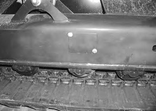
Loosen the top bolt (Item 1) [Figure PM-79]
Remove the bottom bolt and washer (Item 2) [Figure


Pivot the cover out of the way.

TRACK TENSION (CONT’D)
Adjustment (Cont’d)
Add grease to the track tensioner until the track tension indicator (Item 1) is flush with the cylinder edge (Item 2) [Figure PM-83] & [Figure PM-84]

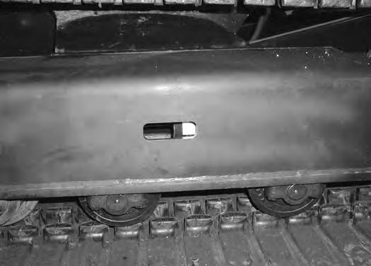
To release track tension, loosen the tensioner (Item 1) [Figure PM-85]. Do not remove the tensioner.
NOTE: Do not remove the tensioner (Item 1) [Figure PM-85] unless pressure is released.
After track tension has been released, remove all grease from the tensioner area.
Repeat the procedure for the other track.

Travel Motor
Checking Oil Level
Figure PM-86
Draining The Travel Motor
See Service Schedule for the correct service interval. (See SERVICE SCHEDULE on Page PM-5.)
Figure PM-87
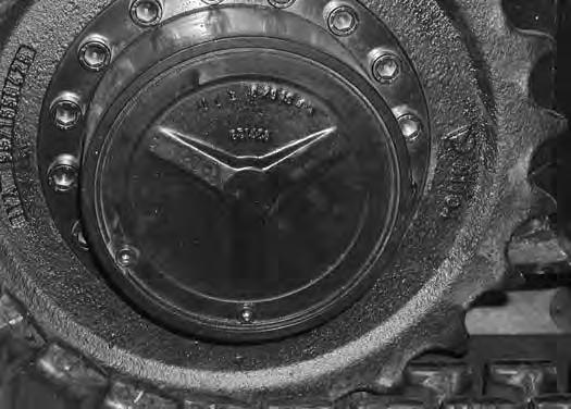
Put the machine on a level surface with the plugs positioned as shown (Item 1 & 2) [Figure PM-86]
Remove the plug (Item 1) [Figure PM-86]. the oil level should be at the bottom edge of the plug hole.
Remove the plug (Item 2) and add gear lube through the hole if the oil level is below the hole (Item 1) [Figure PM86]. (See Capacities on Page SPEC-6.)
Install both plugs.
Repeat the procedure for the other side.
Put the machine on a level surface with the plugs positioned as shown (Item 1 & 2) [Figure PM-87]
Remove both plugs (Items 1 & 2) [Figure PM-87] and drain into a container. Recycle or dispose of the fluid in an environmentally safe manner.
After all the gear lube is removed, rotate the track motor to the position shown [Figure PM-86]
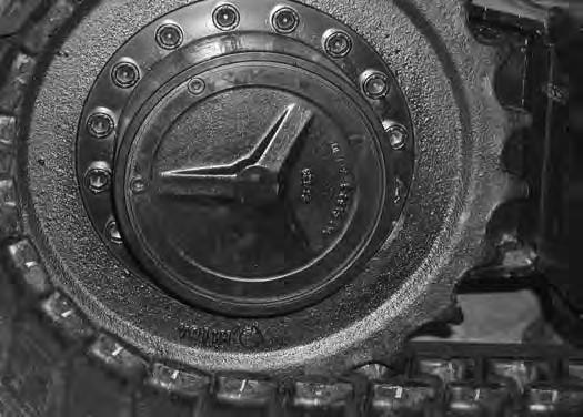
Add gear lube to the plug hole (Item 2) until the gear lube level is at the bottom edge of the plug hole (Item 1) [Figure PM-86] Install and tighten the plugs.
Repeat the procedure for the other side.
Lubricating The Excavator
Lubrication Locations
See Service Schedule for the best performance of the machine. (See SERVICE SCHEDULE on Page PM-5.)
Always use a good quality lithium based multipurpose grease when lubricating the machine. Apply the lubricant until extra grease shows.
Lubricate the following locations on the excavator EVERY 8-10 HOURS:

5.Left blade cylinder base end (1) [Figure PM-89]
6.Left side blade pivot (1) [Figure PM-89]

Ref. Description (# of Fittings)
1.Right blade cylinder rod end (1) [Figure PM-88]
2.Right blade cylinder base end (1) [Figure PM-88]
3.Right side blade pivot (1) [Figure PM-88]