11 minute read
CONTROL CONSOLE LOCKOUTS

from Bobcat 442 Compact Excavator Operation & Maintenance Manual SN ADBR11001 & Above - PDF DOWNLOAD

Inspection And Maintenance
Figure PM-1
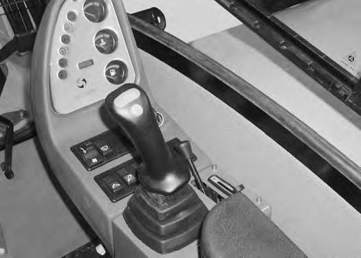
When the left console is raised [Figure PM-1], the hydraulic control levers (joysticks) and traction system must not function.
Sit in the operator's seat, fasten the seat belt and start the engine.
Raise the left console.
Move the joystick control levers. There should be no movement of the boom, arm, slew or bucket.
Move the steering control levers. There should be no movement of the excavator tracks.
Service the system if these controls do not deactivate when the left control console is raised. (See your Bobcat dealer for service.)
Inspection And Maintenance WARNING
Failure to properly inspect and maintain the seat belt can cause lack of operator restraint resulting in serious injury or death.
W-2466-0703
Check the seat belt daily for correct function.
Inspect the seat belt system thoroughly yearly or more often if the machine is exposed to severe environmental conditions or applications.
The seat belt system should be repaired or replaced if it shows cuts, fraying, extreme or unusual wear, significant discolorations due to ultraviolet (UV) rays from the sun, dusty/dirty conditions, abrasion to the seat belt webbing, or damage to the buckle, latch plate, retractor (if equipped), or hardware.
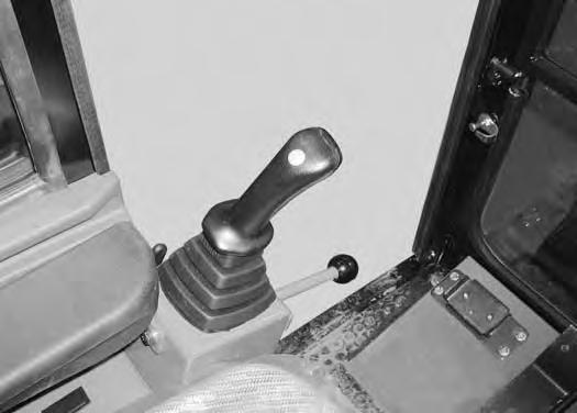
The items below are referenced in [Figure PM-2].
1.Check the seat belt webbing. If the system is equipped with a retractor, pull the webbing completely out and inspect the full length of the webbing. look for cuts, wear, fraying, dirt and stiffness.
2.Check the buckle and latch for proper function. Make sure latch plate is not excessively worn, deformed or buckle is not damaged.
3.Check the retractor web storage device (if equipped) by extending the seat belt webbing to determine if it extends and retracts the webbing correctly.
4.Check webbing in areas exposed to ultraviolet (UV) rays from the sun or extreme dust or dirt. If the original color of the webbing in these areas is extremely faded and / or the webbing is packed with dirt, the webbing strength may have weakened.
See your Bobcat dealer for approved seat belt system replacement parts for your machine.
MOTION ALARM SYSTEM (IF EQUIPPED)
Description

This excavator may be equipped with a motion alarm system. The motion alarm will sound when the operator moves the travel control levers in the either the forward or reverse direction.
Inspecting
Figure PM-3
Inspect for damaged or missing motion alarm decal (Item 1) [Figure PM-3]. Replace if required.
Sit in the operator’s seat. Turn excavator key to ON position but do not start the engine.
Move the travel control levers in the forward direction. The motion alarm must sound. Move the travel control levers in the reverse direction. The motion alarm must sound.
Turn excavator key to OFF position.
The motion alarm is located under the cab on the front of the excavator frame.

NOTE:The excavator will need to be moved slightly in both the forward and reverse direction to test the motion alarm. Keep all bystanders away from machine during test.
Adjustment
Figure PM-4
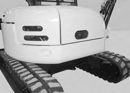
To increase or decrease the alarm sensitivity, position the excavator as shown [Figure PM-4].
Figure PM-5
Remove the eleven bolts (Item 1) and cover (Item 2) [Figure PM-5].
Installation: Tighten the bolts to 18 - 19 ft.-lb. (24 - 26 N•m) torque.

MOTION ALARM SYSTEM (IF EQUIPPED) (CONT’D)
Adjustment (Cont’d)
Figure PM-6
Adjustment screw identification:
(Item 1) [Figure PM-6] Left Forward Travel
(Item 2) [Figure PM-6] Left Reverse Travel
(Item 3) [Figure PM-6] Right Forward Travel
(Item 4) [Figure PM-6] Right Reverse Travel
Turn the adjustment screws counterclockwise to increase motion alarm sensitivity.

Turn the adjustment screws clockwise to decrease motion alarm sensitivity.
Install the cover.
Inspect the motion alarm system for proper function after adjustment.
Opening And Closing
Warning
Avoid Injury Or Death
Never service or adjust the machine when the engine is running unless instructed to do so in the manual.
W-2012-0497
Warning
Keep the rear door closed when operating the machine. Failure to do so could seriously injure a bystander.
W-2020-1285

Right Side Cover
Opening And Closing
Figure PM-8
Push the latch (Item 1) [Figure PM-7] and raise the rear cover.
Lower the rear cover and push down firmly to close the rear cover.

NOTE: The start key can be used to lock the rear cover.
Push the latch (Item 1) [Figure PM-8] and raise the right side cover.
Lower the right side cover and push down firmly to close the rear cover.
NOTE: The start key can be used to lock the right side cover.
Air Cleaner Service

Daily Check
See Service Schedule for the correct service interval. (See SERVICE SCHEDULE on Page PM-5.)
Replacing Filter Elements
Outer Filter
Unlatch the air filter cover latches (Item 2) [Figure PM10]
Remove the air filter cover (Item 3) [Figure PM-10]
Figure PM-11
If the air filter condition indicator (Item 1) [Figure PM-9] is illuminated, the outer filter element needs to be replaced.
Replace the inner filter every third time the outer filter is replaced.
Remove the outer filter (Item 1) [Figure PM-11]
Check the housing for damage.
Clean the housing and seal surface. Do not use compressed air.
Install the outer filter.
Install the cover.
Open the right side cover to inspect the air intake (Item 1) [Figure PM-10] for damage or restrictions. (See RIGHT SIDE COVER on Page PM-10.)

AIR CLEANER (CONT’D)
Replacing Filter Elements (Cont’d)
Inner Filter
Replace the inner filter every third time the outer filter has been replaced.
Replace the inner filter after the outer filter has been replaced and the air filter indicator is still illuminated.

Remove the air cleaner cover and outer filter.
Pry up on the ends of the air filter (Item 1). Pull the air filter (Item 2) [Figure PM-12] out of the housing.

Discard the inner air filter after it has been removed.
Do not clean or reuse the filter. Make sure all sealing surfaces are free of dirt and debris.
Install the new inner filter (Item 1) [Figure PM-13]. Install the outer filter and air cleaner cover.
Fresh Air Filter

Removal And Installation
See Service Schedule for the correct service interval. (See SERVICE SCHEDULE on Page PM-5.)
Position the excavator as shown [Figure PM-14].
Remove the four bolts (Item 1) [Figure PM-16]
Remove the filter (Item 2) [Figure PM-16]
Remove the eleven bolts (Item 1) [Figure PM-15] and washers.
Installation: Tighten the bolts to 18 - 19 ft.-lb. (24 - 26 N•m) torque.
Remove the cover (Item 2) [Figure PM-15]
Fuel System
Fuel Specifications
Use only clean, high quality diesel fuel, Grade No. 2 or Grade No. 1.
The following is a suggested blending guideline which should prevent fuel gelling during freezing temperatures:
Biodiesel Blend Fuel
Biodiesel blend fuel has unique qualities that should be considered before using in this machine:
•Cold weather conditions can lead to plugged fuel system components and hard starting.
•Biodiesel blend fuel is an excellent medium for microbial growth and contamination which can cause corrosion and plugging of fuel system components.
•Use of biodiesel blend fuel may result in premature failure of fuel system components, such as plugged fuel filters and deteriorated fuel lines.
At a minimum, Low Sulfur (500 ppm sulfur) Diesel Fuel must be used in this machine.
The following fuels may also be used in this machine:
•Ultra Low Sulfur (15 ppm sulfur) Diesel Fuel.
•Biodiesel Blend Fuel - Must contain no more than five percent biodiesel mixed with low sulfur or ultra low sulfur petroleum based diesel. This is commonly marketed as B5 blended diesel fuel.
Warning
AVOID INJURY OR DEATH
Stop and cool the engine before adding fuel. NO SMOKING! Failure to obey warnings can cause an explosion or fire.
W-2063-0807
Warning
AVOID INJURY OR DEATH
Always clean up spilled fuel or oil. Keep heat, flames, sparks or lighted tobacco away from fuel and oil. Failure to use care around combustibles can cause explosion or fire.
W-2103-0508
•Shorter maintenance intervals may be required, such as cleaning the fuel system and replacing fuel filters and fuel lines.
•Using biodiesel blended fuels containing more than five percent biodiesel can affect engine life and cause deterioration of hoses, tubelines, injectors, injector pump and seals.
Apply the following guidelines if biodiesel blend fuel is used:
•Ensure the fuel tank is as full as possible at all times to prevent moisture from collecting in the fuel tank.
•Ensure that the fuel tank cap is securely tightened.
•Biodiesel blend fuel can damage painted surfaces, remove all spilled fuel from painted surfaces immediately.
•Drain all water from the fuel filter daily before operating the machine.
•Do not exceed engine oil change interval. Extended oil change intervals can cause engine damage.
•Before vehicle storage; drain the fuel tank, refill with 100% petroleum diesel fuel, add fuel stabilizer and run the engine for at least 30 minutes.
NOTE:Biodiesel blend fuel does not have long term stability and should not be stored for more than three months.
FUEL SYSTEM (CONT’D)
Filling The Fuel Tank
Figure PM-17
Warning
AVOID INJURY OR DEATH
Stop and cool the engine before adding fuel. NO SMOKING! Failure to obey warnings can cause an explosion or fire.
W-2063-0807
Pre-Filter Removal And Installation (If Equipped)
Open the rear cover and remove the fuel fill cap (Item 1) [Figure PM-17]
NOTE: The fuel fill cap can be locked. Use the fuel fill cap key to lock and unlock the cap.
Check the condition of the fill strainer screen (Item 1) [Figure PM-18]. Clean or replace as necessary.
Use a clean, approved safety container to add fuel. Add fuel only in an area that has a free movement of air and no flames or sparks. NO SMOKING!

Install and tighten the fuel fill cap. Close the rear cover.
See Service Schedule for the service interval when to remove water from the fuel pre-filter or replace the fuel pre-filter and fuel filter. (See SERVICE SCHEDULE on Page PM-5.)

FUEL SYSTEM (CONT’D)
Fuel Filter Removal And Installation
See Service Schedule for the service interval when to replace the fuel filter. (See SERVICE SCHEDULE on Page PM-5.)
Clean the area around the filter.
Figure PM-20
Remove the filter (Item 1) [Figure PM-20]
Put clean oil on the seal of the new filter.
Install the filter and hand tighten.
NOTE:If air needs to be bled from the fuel system, a manual pump (Item 2) [Figure PM-20] can be used to pump fuel through the fuel system. Pull out and push in on the knob until a strong resistance is felt and pressure has been built up. Start the engine and run at low idle until any air is removed from the fuel system.
FUEL SYSTEM (CONT’D)

Draining The Fuel Tank


Warning
AVOID
Injury Or Death
Always clean up spilled fuel or oil. Keep heat, flames, sparks or lighted tobacco away from fuel and oil. Failure to use care around combustibles can cause explosion or fire.
Engine Lubrication System

Checking Engine Oil
Check the engine oil after every 8-10 hours of operation and before starting the engine for the work shift.
Figure PM-24
Open the right side cover and remove the dipstick (Item 1) [Figure PM-24].
Keep the oil level between the marks on the dipstick.
Use a good quality motor oil that meets the correct API Service Classification. (See REGULAR MAINTENANCE ITEMS on Page V.)
Oil Chart
Figure PM-25
ENGINE OIL
RECOMMENDED SAE VISCOSITY NUMBER (LUBRICATION OILS FOR DIESEL ENGINE CRANKCASE)
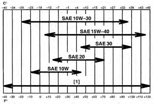
TEMPERATURE RANGE ANTICIPATED BEFORE NEXT OIL CHANGE (DIESEL ENGINES MUST USE API CLASSIFICATION CI-4 OR BETTER)
[1] Synthetic Oil - Use recommendation from Synthetic Oil Manufacturer.
Use a good quality engine oil that meets the correct API Service Classification. See oil chart [Figure PM-25]
ENGINE LUBRICATION SYSTEM (CONT’D)


Removing And Replacing Oil And Filter
See Service Schedule for the service interval for replacing the engine oil and filter. (See SERVICE SCHEDULE on Page PM-5.)
Drain the oil in a container.
Recycle or dispose of used oil in an environmentally safe manner.
Rotate the upperstructure so the right side is positioned between the tracks [Figure PM-26]. Run the engine until it is at operating temperature. Stop the engine.
Open the right side cover.
ENGINE LUBRICATION SYSTEM (CONT’D)
Removing And Replacing Oil And Filter (Cont’d)
Figure PM-29
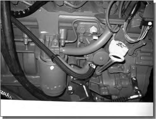
Remove the oil filter (Item 1) [Figure PM-29] and clean the filter housing surface.
Use a genuine Bobcat replacement oil filter.
Put clean engine oil on the filter gasket. Install the filter and hand tighten.
Remove the drain hose and install the cap on the oil pan after the oil has been completely drained.
Remove the fill cap (Item 2) [Figure PM-29].
Put oil in the engine. (See REGULAR MAINTENANCE ITEMS on Page V.) (See Capacities on Page SPEC-6.)
Install the fill cap.
Start the engine and let it run for several minutes.
Stop the engine. Check for leaks at the oil filter. Check the oil level on the dipstick (Item 3) [Figure PM-29]
Add oil as needed if it is not at the top mark on the dipstick.
Engine Cooling System

Cleaning
Check the cooling system every day to prevent overheating, loss of performance or engine damage.
Open the right side cover.
Use air pressure or water pressure to clean the radiator/ oil cooler. Be careful not to damage the fins when cleaning.

Checking Level
Warning
AVOID BURNS
Do not remove radiator cap when the engine is hot. You can be seriously burned.
W-2070-1203
Open the right side cover.
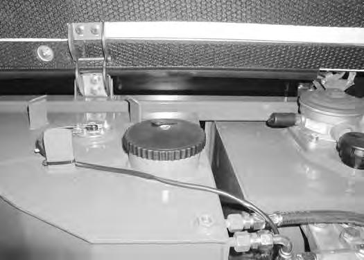
Check the coolant level in the surge tank (Item 1) [Figure PM-30]
NOTE:There is a sight gauge located on the surge tank that can also be used for checking the coolant level.
The surge tank (Item 1) [Figure PM-31] must be half full when the engine is cold.
Important
AVOID ENGINE DAMAGE
Always use the correct ratio of water to antifreeze.
Too much antifreeze reduces cooling system efficiency and may cause serious premature engine damage.
Too little antifreeze reduces the additives which protect the internal engine components; reduces the boiling point and freeze protection of the system.
Always add a premixed solution. Adding full strength concentrated coolant can cause serious premature engine damage.
I-2124-0497
Warning
AVOID INJURY OR DEATH
Wear safety glasses to prevent eye injury when any of the following conditions exist:
•When fluids are under pressure.
•Flying debris or loose material is present.
•Engine is running.
•Tools are being used.
W-2019-0907
ENGINE COOLING SYSTEM (CONT’D)
Removing And Replacing Coolant
See Service Schedule for the correct service interval to replace the coolant. (See SERVICE SCHEDULE on Page PM-5.)
Warning
AVOID BURNS
Do not remove radiator cap when the engine is hot. You can be seriously burned.
NOTE: The plug is located next to the alternator mount bracket.
Drain the coolant from the engine.
Figure PM-34
When the engine is cool, loosen and remove the radiator cap (Item 1) [Figure PM-32]
Remove the lower radiator hose (Item 1) [Figure PM-34]
Drain the coolant from the engine.
After the coolant is removed, install the plug (Item 1) [Figure PM-33] and lower radiator hose (Item 1) [Figure PM-34]

Recycle or dispose of the used coolant in an environmentally safe manner.
Mix the coolant in a separate container.
NOTE: The excavator is factory filled with ethylene glycol coolant.
Add premixed coolant, 50% water and 50% ethylene glycol to the reservoir if the coolant level is low.
One gallon (3,8 L) of ethylene glycol mixed with one gallon (3,8 L) of water is the correct mixture of coolant to provide a -34°F (-37°C) freeze protection.
Use a refractometer to check the condition of ethylene glycol in your cooling system.
Fill the radiator with the premixed coolant. Install the radiator cap.
Run the engine until it is at operating temperature.
Stop the engine.
Remove the plug (Item 1) [Figure PM-33] from the back side of the engine block.
ENGINE COOLING SYSTEM (CONT’D)
Removing And Replacing Coolant (Cont’d)
Check the coolant level (COLD) in the surge tank (Item 1) [Figure PM-35] when cool.
Add coolant to the tank as needed.