7 minute read
TRAVEL CONTROLS

from Bobcat 442 Compact Excavator Operation & Maintenance Manual SN ADBR11001 & Above - PDF DOWNLOAD

Description
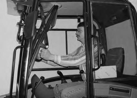
The travel control levers control the movement of the excavator.
Forward And Reverse Travel
NOTE: The following procedures describe forward, reverse, left & right as seated in the operator's seat.
Turning Right Turn
Figure OI-28
Put the blade so that it is at the front of the machine (as you sit in the operator's seat). Slowly move both steering levers* (Item 1) [Figure OI-27] forward for forward travel; backward for reverse travel.

* Steering can also be controlled with foot pedals (Item 2) [Figure OI-27]
Warning
AVOID INJURY OR DEATH
•Check the blade location before traveling. When the blade is to the rear, operate the steering levers/foot pedals in the opposite direction to when the blade is in the front.
•Move the steering levers/foot pedals slowly. Abrupt lever motion will cause the machine to jerk.
W-2235-0396
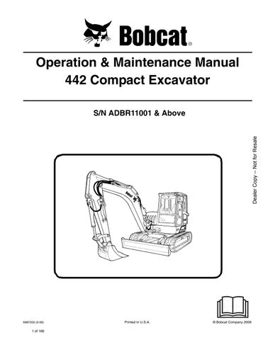
Push the left steering lever forward to turn right [Figure OI-28] while traveling forward.
Figure OI-29
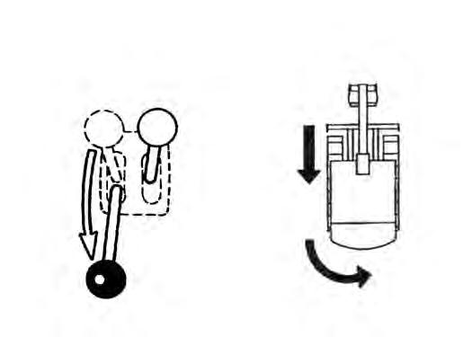
Pull the left steering lever backward to turn right [Figure OI-29] while traveling backward.
TRAVEL CONTROLS (CONT’D)
Turning (Cont’d)
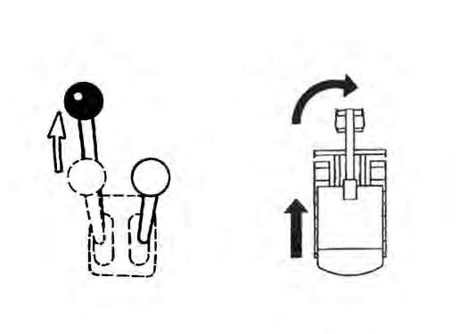
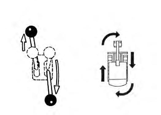
Counter-Rotation Right Turn
Figure OI-30
Push the left steering lever forward and pull the right steering lever backward [Figure OI-30].
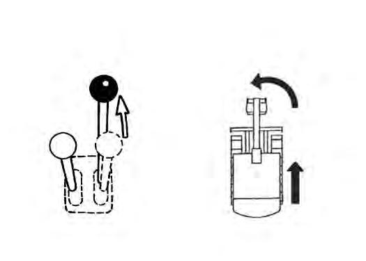
Left Turn
Figure OI-31
Push the right steering lever forward to turn left while traveling forward [Figure OI-31]

Pull the right steering lever backward to turn left while traveling backward [Figure OI-32]
Counter-Rotation Left Turn
Figure OI-33
Push the right steering lever forward and pull the left steering lever backward [Figure OI-33]

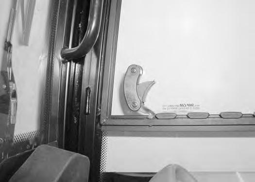
Emergency Exit
The left door, right side window and front window provide exits.

Right Side Window
Front Window
NOTE:If the excavator has a FOGS Kit installed, the front window is NOT an emergency exit.

Turn
Continue moving the window in and up over the
MOTION ALARM SYSTEM (IF EQUIPPED) Operation
Warning
This machine is equipped with a motion alarm. ALARM MUST SOUND! when operating forward or backward.

Failure to maintain a clear view in the direction of travel could result in serious injury or death.
The operator is responsible for the safe operation of this machine.
W-2786-0309
The motion alarm will sound when the operator moves the travel control levers in the either the forward or reverse direction.
If alarm does not sound or for adjustment instructions, see inspection and maintenance instructions for the motion alarm system in the preventive maintenance section of this manual. (See MOTION ALARM SYSTEM (IF EQUIPPED) on Page PM-8.)

Hydraulic Controls
Description
The work equipment (boom, arm, bucket, and upperstructure slew) is operated by using the right and left control levers (joysticks).
Standard Control Pattern
Left Control Lever (Joystick)


Figure OI-40
The left lever is used to operate the boom and slew the upperstructure [Figure OI-40].
1.Boom lower
2.Boom lower and slew right
3.Slew right
4.Boom raise and slew right
5.Boom raise
6.Boom raise and slew left
7.Slew left
8.Boom lower and slew left
Right Control Lever (Joystick)
Figure OI-41
The
OI-41]
1.Arm out
2.Arm out and bucket dump
3.Bucket dump
4.Arm in and bucket dump
5.Arm in
6.Arm in and bucket curl
7.Bucket curl
8.Arm out and bucket curl
WARNING
AVOID INJURY OR DEATH
Before leaving the machine:
•Lower the work equipment to the ground.
•Lower the blade to the ground.
•Stop the engine & remove the key.
W-2196-0595
HYDRAULIC CONTROLS (CONT’D)
ISO Control Pattern
Left Control Lever (Joystick)
The left lever is used to operate the arm and to slew the upperstructure [Figure OI-42]
1.Arm out
2.Arm out and slew right
3.Slew right
4.Arm in and slew right
5.Arm in
6.Arm in and slew left
7.Slew left
8.Arm out and slew left
Right Control Lever (Joystick)


The right lever is used to operate the boom and bucket [Figure OI-43].
1.Boom lower
2.Boom lower and bucket dump
3.Bucket dump
4.Boom raise and bucket dump
5.Boom raise
6.Boom raise and bucket curl
7.Bucket curl
8.Boom lower and bucket curl
WARNING
AVOID INJURY OR DEATH
Before leaving the machine:
•Lower the work equipment to the ground.
•Lower the blade to the ground.
•Stop the engine & remove the key.
W-2196-0595
HYDRAULIC CONTROLS (CONT’D)
Quick Couplers
The excavator and attachments are equipped with thread together and poppet style couplers.
The excavator has quick couplers installed on both sides of the arm.
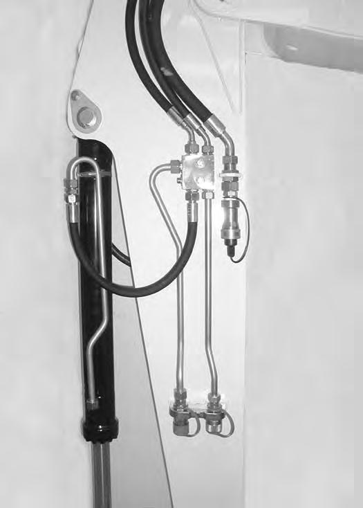
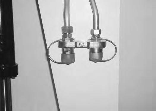
The female quick couplers (Item 1) [Figure OI-44] & [Figure OI-45] are used for standard auxiliary hydraulic functions (hydraulic breaker, clamshell, bucket rotation and swing bucket).
The male quick couplers (Item 2) [Figure OI-44] & [Figure OI-45] are used for dual auxiliary hydraulic functions (opening and closing the clamshell bucket).
The female quick coupler (Item 3) [Figure OI-45] is a direct to tank return line.

Warning
Avoid Burns
Hydraulic fluid, tubes, fittings and quick couplers can get hot when running machine and attachments. Be careful when connecting and disconnecting quick couplers.
HYDRAULIC CONTROLS (CONT’D)
Quick Couplers (Cont’d)
To Connect:
Figure OI-46
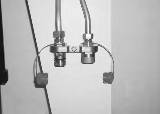
Remove any dirt or debris from the surface of both the male and female couplers. Visually check the couplers for corroding, cracking, damage, or excessive wear. If any of these conditions exist, the coupler(s) must be replaced. Remove the protective caps (Item 1) [Figure OI-46]

Thread the couplers (Item 1) from the attachment to the couplers (Item 2) [Figure OI-47] on the excavator. Tighten the couplers until fully seated.

Example: Connect the clamshell bucket rotation to the female couplers (Item 1) [Figure OI-48] & [Figure OI49].
Connect the clamshell bucket open/close cylinder to the male quick couplers (Item 2) [Figure OI-48] & [Figure OI-49]

Thread the protective caps (Item 3) [Figure OI-49] together.
HYDRAULIC CONTROLS (CONT’D)
Quick Couplers (Cont’d)
Connect the return to tank line from the attachment to the female (poppet style) quick coupler (Item 1) [Figure OI50] (if required).
Turn the diverter valve (Item 2) [Figure OI-50] to direct hydraulic flow to the auxiliary quick couplers for clamshell open / close functions bucket.
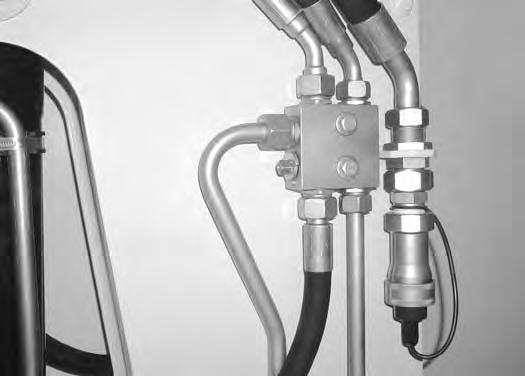
NOTE: The bucket cylinder is inoperable when the diverter valve is turned for dual auxiliary hydraulic operation.
To Disconnect
Unthread the couplers on the attachment from the excavator. Remove the return to tank line (if installed) from the female coupler (Item 1) [Figure OI-50]
Turn the diverter valve (Item 2) [Figure OI-50] back to restore hydraulic flow to the bucket cylinder.
HYDRAULIC CONTROLS (CONT’D)
Auxiliary Hydraulics
The switches (Item 1 & 2) [Figure OI-52] are used for hydraulic powered attachments (such as a clamshell bucket).
Push and hold the switch (Item 1) [Figure OI-52] to provide hydraulic flow to the quick couplers. Release the switch to stop hydraulic flow.

Push and hold the switch (Item 2) [Figure OI-52] to reverse the direction of flow to the quick couplers. Release the switch to stop hydraulic flow.
For proper hydraulic breaker operation, press the switch (Item 1) [Figure OI-53]. The switch will be illuminated. The switch allows full hydraulic flow to the right side coupler for breaker operation.
Press and hold the switch (Item 1) [Figure OI-54] to provide hydraulic flow to the hydraulic breaker. Release the switch to stop hydraulic flow.
NOTE: Left side of the switch (Item 2) [Figure OI-54] is inoperable when the hydraulic breaker operation switch (Item 1) [Figure OI-53] is activated.

HYDRAULIC CONTROLS (CONT’D)
Relieving Hydraulic Pressure
Stop the engine and turn the key to the RUN position.
HYDRAULIC CONTROLS (CONT’D)
Upperstructure Slew Brake
When slewing the upperstructure while working on a slope, push and hold the slew brake button (Item 1) [Figure OI-57] until the slew circuit is engaged. Release the button when the upperstructure starts to slew. This will prevent the upperstructure from drifting when the slew circuit is first engaged.
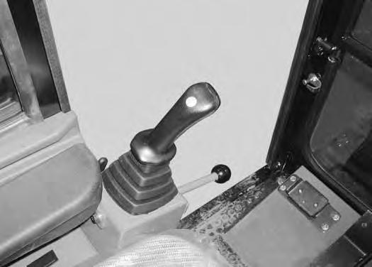
BLADE CONTROL LEVER Operation
BOOM SWING PEDAL Operation
Push the left side of the pedal (Item 2) [Figure OI-58] to swing the boom to the left.
Push the right side of the pedal (Item 2) [Figure OI-58] to swing the boom to the right.
Push the lever (Item 1) [Figure OI-58] forward to lower the blade.
Pull the lever (Item 1) [Figure OI-58] backward to raise the blade.
NOTE: Keep the blade lowered when digging to help stabilize the excavator.
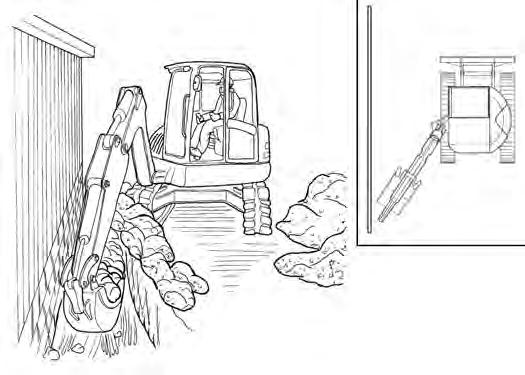
NOTE: The purpose of the boom swing pedal is to offset the boom with respect to the upperstructure for digging close to a structure [Figure OI-60].
Push the switch (Item 1) [Figure OI-59] to put the blade in the float position (the switch will be illuminated).
Daily Inspection
DAILY INSPECTION (CONT’D)
Daily Inspection And Maintenance
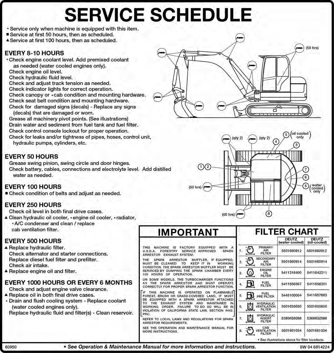
Maintenance work must be done at regular intervals. Failure to do so will result in excessive wear and early failures. The Service Schedule [Figure OI-61] is a guide for correct maintenance of the Bobcat Excavator. It is located inside the rear door of the excavator and also in this manual.
Check the following items before each day of operation:
•Operator Cab and mounting hardware.
•Seat belt and mounting hardware.
•Damaged decals, replace as needed.
•Indicator lights for proper operation.
•Check control console lockout.
•Air cleaner and intake hoses.
•Engine oil level and for engine leaks.
•Engine coolant level and for leaks.
•Hydraulic fluid level and system for leaks.
•Grease all pivot points.
•Cylinder and attachment pivot points.
•Drain water and sediment from fuel tank and filter.
•Track tension.
•Repair broken and loose parts.
Warning
AVOID INJURY OR DEATH
Instructions are necessary before operating or servicing machine. Read and understand the Operation & Maintenance Manual, Operator’s Handbook and signs (decals) on machine. Follow warnings and instructions in the manuals when making repairs, adjustments or servicing. Check for correct function after adjustments, repairs or service. Untrained operators and failure to follow instructions can cause injury or death.
W-2003-0807
Fluids such as engine oil, hydraulic fluid, coolants, etc. must be disposed of in an environmentally safe manner. Some regulations require that the certain spills and leaks on the ground must be cleaned in a specific manner. See local, state and federal regulations for correct disposal.
Important
Pressure Washing Decals
•Never direct the stream at a low angle toward the decal that could damage the decal causing it to peel from the surface.
•Direct the stream at a 90 degree angle and at least 12 inches (300 mm) from the decal. Wash from the center of the decal toward the edges.
I-2226-0104
PRE-STARTING PROCEDURE
Operation And Maintenance Manual And Operator’s Handbook Locations
Entering And Exiting The Excavator

Read and understand the Operation & Maintenance Manual (Item 1) (located in the compartment behind the operator seat) and the Operator's Handbook (Item 2) [Figure OI-62] before operating.

Warning
AVOID INJURY OR DEATH
Instructions are necessary before operating or servicing machine. Read and understand the Operation & Maintenance Manual, Operator’s Handbook and signs (decals) on machine. Follow warnings and instructions in the manuals when making repairs, adjustments or servicing. Check for correct function after adjustments, repairs or service. Untrained operators and failure to follow instructions can cause injury or death.
Important
Pressure Washing Decals
•Never direct the stream at a low angle toward the decal that could damage the decal causing it to peel from the surface.
•Direct the stream at a 90 degree angle and at least 12 inches (300 mm) from the decal. Wash from the center of the decal toward the edges.