10 minute read
STARTING THE ENGINE (CONT’D)

from Bobcat 442 Compact Excavator Operation & Maintenance Manual SN ADBR11001 & Above - PDF DOWNLOAD

Cold Temperature Starting Procedure
Important
Do not engage the starter for longer than 15 seconds at a time. Longer use can damage the starter by overheating. Allow starter to cool for one minute before using starter again.
I-2034-0700
If the temperature is below freezing, perform the following to make starting the engine easier:
Replace the engine oil with the correct type and viscosity for the anticipated starting temperature. (See Oil Chart on Page PM-18.)
Make sure the battery if fully charged.
NOTE: If the battery is discharged (but not frozen) a booster battery can be used to jump start the excavator. (See Using A Booster Battery (Jump Starting) on Page PM-27.)
Install an engine heater.
Move the speed control lever (Item 1) [Figure OI-76] back to the high speed position.
Turn the key (Item 2) [Figure OI-76] to the RUN/ PREHEAT position.
The air intake heater light (Item 1) [Figure OI-77] will be illuminated showing the air intake heater is on. Wait for the light to go off.
When the light goes out, turn the key to the start position and release the key when the engine starts. The key will return to the run position. When the engine speed increases, move the speed control lever to the low speed position until the engine warms up. Turn the key switch off to stop the engine.

Important
Do not engage the starter for longer than 15 seconds at a time. Longer use can damage the starter by overheating. Allow starter to cool for one minute before using starter again.
I-2034-0700
Important
Machines warmed up with moderate engine speed and light load have longer life.
I-2015-0284
Warning
AVOID INJURY OR DEATH
Do not use ether with glow plug (preheat) systems. Explosion can result which can cause injury, death, or severe engine damage.
W-2071-0907
Stopping The Engine And Leaving The Excavator

Procedure
Stop the machine on level ground. Lower the work equipment and the blade to the ground.
Move the engine speed control (Item 1) [Figure OI-78] fully forward to the low speed position.
Let the engine run at idle speed for five minutes before stopping the engine.
Turn the key switch (Item 1) [Figure OI-79] to the STOP position.
Disconnect the seat belt. Remove the key from the switch to prevent operation of machine by unauthorized personnel. Raise the control console and exit the machine.
Attachments
Bucket And Ripper Tooth Installation


Warning
AVOID INJURY OR DEATH
Never use attachments or buckets which are not approved by Bobcat Company. Buckets and attachments for safe loads of specified densities are approved for each model. Unapproved attachments can cause injury or death.
W-2052-0907
Warning
Keep all bystanders 20 feet (6 m) away from equipment when operating. Contact with moving parts, a trench cave-in or flying objects can cause injury or death.
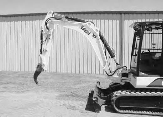
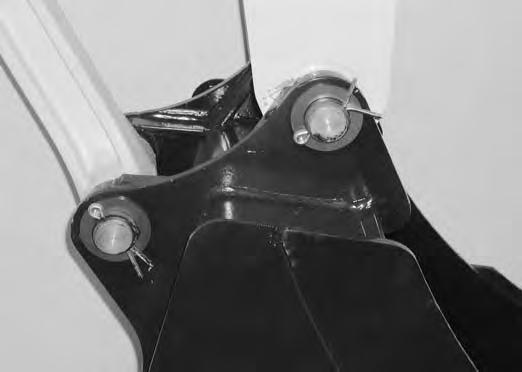
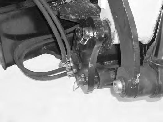
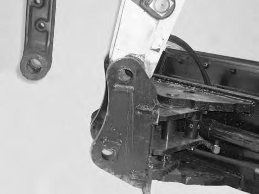
Lower the arm (Item 1) and bucket link (Item 2) [Figure OI-81] in to the bucket mount.
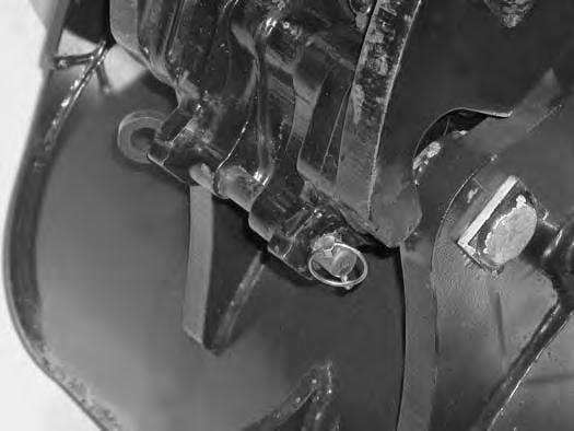
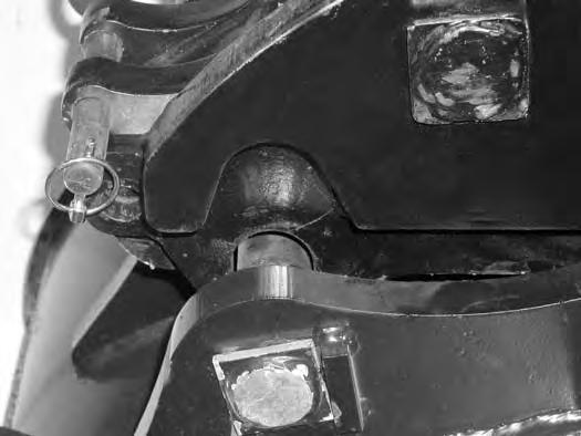
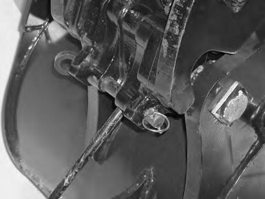
Install the pins (Item 3) [Figure OI-81].
The pins must seat against the anti-rotation stops (Item 4) [Figure OI-81].
Install the washers (Item 1) [Figure OI-82]

ATTACHMENTS (CONT’D)
Bucket And Ripper Tooth Removal

Stop the excavator on a flat level surface. Put the bucket on the ground.

ATTACHMENTS (CONT’D)
Tilt Bucket Installation
Warning
Avoid Injury Or Death
Never use attachments or buckets which are not approved by Bobcat Company. Buckets and attachments for safe loads of specified densities are approved for each model. Unapproved attachments can cause injury or death.
W-2052-0907
Install
The pins must seat against the anti-rotation stops (Item 2) [Figure
.

ATTACHMENTS (CONT’D)

Tilt Bucket Installation (Cont’d)
Tilt Bucket Removal
Relieve hydraulic pressure. (See Relieving Hydraulic Pressure on Page
Remove
ATTACHMENTS (CONT’D)
Tilt Bucket Operation
NOTE: The side to side movement of the tilt bucket can be slowed by adjusting the auxiliary hydraulic flow. (See Auxiliary Hydraulics on Page OI-21.)


Push and hold the switch (Item 1) [Figure OI-94] to swing the bucket to the left [Figure OI-95]. Release the button when the correct position of the bucket is obtained.
Keep all bystanders 20 feet (6 m) away from equipment when operating. Contact with moving parts, a trench cave-in or flying objects can cause injury or death.
Push and hold the switch (Item 2) [Figure OI-94] to swing to the right [Figure OI-96]. Release the button when the correct position of the bucket is obtained.
(See Auxiliary Hydraulics on Page OI-21.)
ATTACHMENTS (CONT’D)
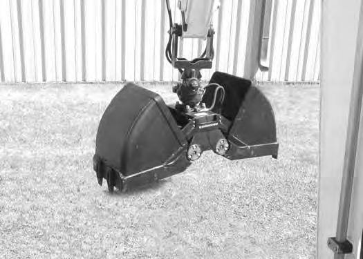
Clamshell Bucket Installation
Fully
ATTACHMENTS (CONT’D)
Clamshell Bucket Installation (Cont’d)


Turn

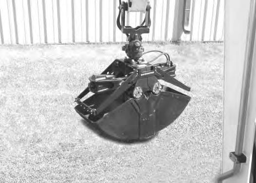
ATTACHMENTS (CONT’D)
Clamshell Bucket Installation (Cont’d)


ATTACHMENT (CONT’D)
Clamshell Bucket Installation (Cont’d)
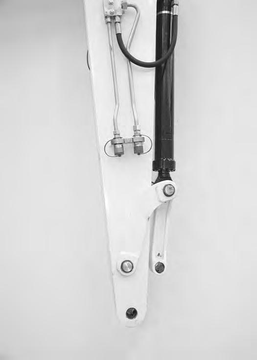
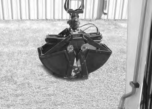
Install the hydraulic hoses (Item 1) [Figure OI-107] from the clamshell to the excavator quick couplers.
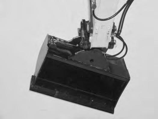
Clamshell Bucket Removal
Lower the clamshell to the ground. Use the boom and arm functions to position the clamshell as shown [Figure OI-108].

Remove the hydraulic hoses from the excavator quick couplers.

ATTACHMENT (CONT’D)
Clamshell Bucket Operation WARNING
Keep all bystanders 20 feet (6 m) away from equipment when operating. Contact with moving parts, a trench cave-in or flying objects can cause injury or death.
ATTACHMENTS (CONT’D)
Clamshell Bucket Operation (Cont’d)
ATTACHMENTS (CONT’D)
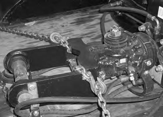
Lifting The Clamshell Bucket
NOTE: Use chains that are in good condition and of adequate size to lift the attachment.


ATTACHMENTS (CONT’D)
Fastening The Clamshell Bucket To The Transport Vehicle
Use chain binders to prevent the attachment from moving during transport.

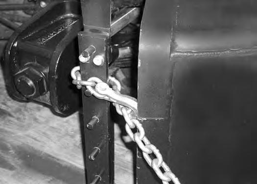
Secure the hydraulic hoses to the attachment.
ATTACHMENTS (CONT’D)
Manual Spring Loaded Coupler Installation
Remove the bucket. (See Bucket And Ripper Tooth Removal on Page OI-35.)
Warning
AVOID INJURY OR DEATH
Never use attachments or buckets which are not approved by Bobcat Company. Buckets and attachments for safe loads of specified densities are approved for each model. Unapproved attachments can cause injury or death.
W-2052-0907
NOTE: Align
ATTACHMENTS (CONT’D)
Manual Spring Loaded Coupler Removal
ATTACHMENTS (CONT’D)
Manual Spring Loaded Coupler Attachment Installation WARNING


Keep all bystanders 20 feet (6 m) away from equipment when operating. Contact with moving parts, a trench cave-in or flying objects can cause injury or death.
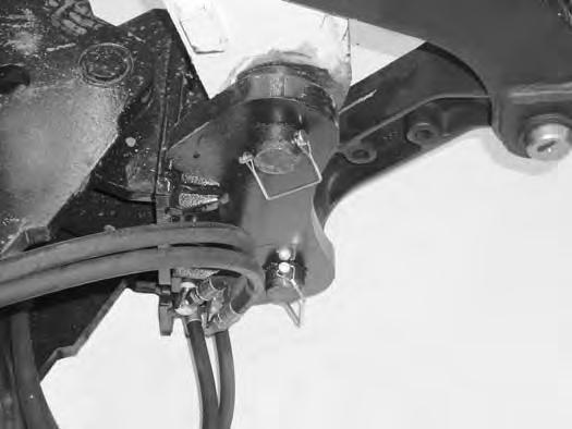
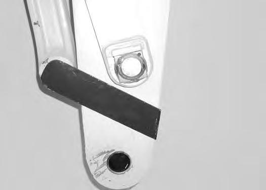
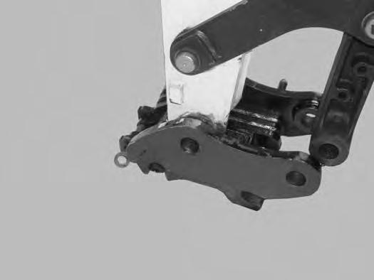
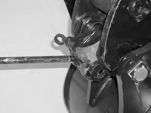
Using the release bar (Item 1), rotate the locking hooks (Item 2) [Figure OI-129] upwards to the unlock position.
Insert the release bar (Item 1) into the manual spring loaded coupler. Remove the retainer pin (Item 2). Rotate the release bar (Item 1) upward slightly and remove the lock pin (Item 3) [Figure OI-128]

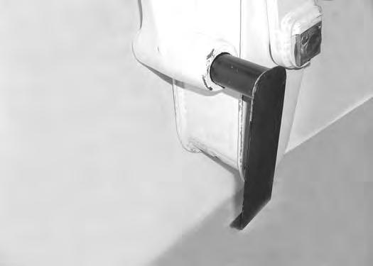
Install the lock pin (Item 1) and retainer pin (Item 2) [Figure OI-130] to hold the locking hooks in the open position. Remove the release bar.

Enter the machine, fasten the seat belt and start the engine.
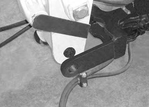
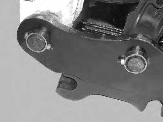
Position the front hooks (Item 1) over the front pin (Item 2) [Figure OI-131] of the attachment.
ATTACHMENTS (CONT’D)
Manual Spring Loaded Coupler Attachment Installation (Cont'd)
Extend the bucket cylinder (curl in) the coupler until the rear pin of the attachment (Item 1) is firmly seated in the coupler (Item 2) [Figure OI-132].
Continue to curl the coupler and attachment until the weight of the attachment is supported by the coupler.
Stop the engine and exit the machine.
Rotate the locking hooks (Item 1) downward, cupping (engaging) the attachment pin (Item 2) [Figure OI-134]
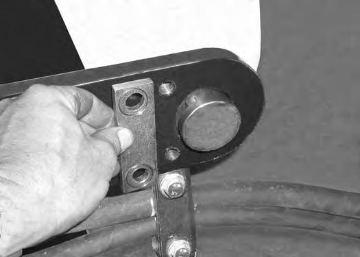
Reinsert the release bar (Item 1) and rotate the locking hooks (Item 2) [Figure OI-133] upwards slightly.
Remove the retainer pin and the locking pin (Item 3) [Figure OI-133].
Install the locking pin (Item 1) and retainer pin (Item 2) [Figure OI-135] and remove the release bar.
Check for secure attachment. Never operate without retainer pins (Item 2) [Figure OI-135] installed.

ATTACHMENTS (CONT’D)
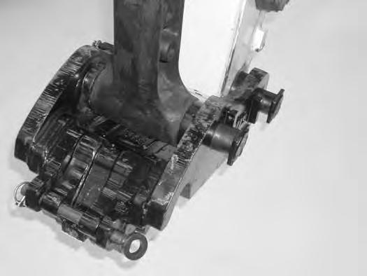
Manual Spring Loaded Coupler Attachment Removal
Figure OI-136
Position the attachment flat on the ground. Stop the engine and exit the machine.
Remove the retainer pin (Item 1) [Figure OI-136].
Insert the release bar (Item 2) and rotate the release bar upward slightly and remove the locking pin (Item 3)
[Figure
Using the release bar (Item 1), rotate the locking hooks (Item 2) upwards to the unlock position and install the locking pin (Item 3) [Figure OI-137]
Install the retainer pin (Item 1) [Figure OI-138] to hold the locking hooks in the open position. Remove the release bar.
Enter the machine, fasten the seat belt and start the engine.
Retract the bucket cylinder and move the arm forward until the manual spring loaded coupler is clear of the attachment [Figure OI-139]


OPERATING PROCEDURE Inspect The Work Area
Before beginning operation, inspect the work area for unsafe conditions.
Look for sharp drop-offs or rough terrain. Have underground utility lines (gas, water, sewer, irrigation, etc.) located and marked.
Remove objects or other construction material that could damage the excavator or cause personal injury.
Lowering The Work Equipment (Engine STOPPED)
The hydraulic control levers (joysticks) control the movement of the boom, arm, bucket and upperstructure slew functions.
The left console must be in the locked down position, and the key switch in the ON position.
Operating On Public Roads
When operating on a public road or highway, always follow local regulations. For example: A slow moving vehicle (SMV) sign, or direction signals may be required.
Check with utility companies for underground electrical, water, gas lines, etc. Work slowly in areas of underground utilities.
Warning
AVOID INJURY OR DEATH
Do not exceed Rated Operating Capacity (ROC). Excessive load can cause tipping or loss of control.
Push down on the handle (Item 1) [Figure OI-140] and lock the console in the down position.
Use the control lever (joystick) to lower the boom.
NOTE: If the engine stops, the boom / bucket (attachments) can be lowered to the ground using hydraulic pressure in the accumulator.

The control console must be in the locked down position, and the key switch in the ON position.
Use the control lever (joystick) to lower the boom.
OPERATING PROCEDURE (CONT’D)
Lifting A Load
Do not exceed the rated load capacity. (See LIFT CHART (6813628) on Page MST-4.)
Warning
AVOID INJURY OR DEATH
Do not exceed rated lift capacity. Excessive load can cause tipping or loss of control.
W-2374-0500
Extend the bucket cylinder completely and lower the boom to the ground. Stop the engine.
Wrap the chain assembly around the bucket mounting plate.
Make sure the load is evenly weighted and centered on the lifting chain, and is secured to prevent the load from shifting [Figure OI-141]
Lift and position the load. When the load is in position and tension is removed from the lift chain (secondary lift system), remove the secondary lift system.
Warning
AVOID INJURY OR DEATH
Keep objects balanced and as close to the backhoe and ground as possible when lifting with the backhoe. Swing lifted objects slowly. Always lower objects to the ground before leaving the machine.
W-2115-0189
OPERATING PROCEDURE (CONT’D)
Excavating
Warning
AVOID INJURY OR DEATH
Check area to be excavated for overhead or underground lines such as electrical, gas, oil, water, etc. CALL 1-888-258-0808 and consult local utilities before digging. Extreme caution must be used in areas where utility lines are present.
W-2116-0903
Lower the blade to provide stability.
Figure OI-142
Extend the arm, lower the boom and open the bucket [Figure OI-142]


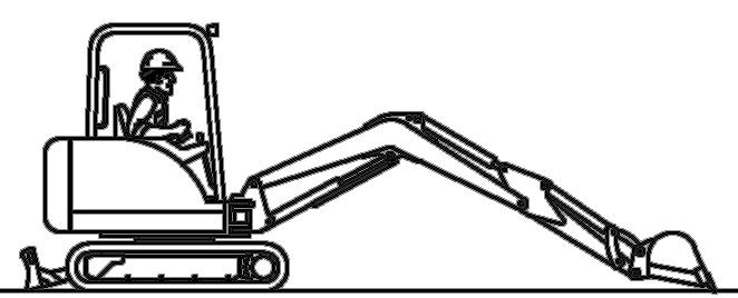
Figure OI-143
Raise the boom, retract the arm and curl the bucket [Figure OI-144]
Rotate the upperstructure.
NOTE: Do not allow the bucket teeth to contact the ground when swinging the upperstructure.
Warning
Keep all bystanders 20 feet (6 m) away from equipment when operating. Contact with moving parts, a trench cave-in or flying objects can cause injury or death.
W-2119-0788
Warning
AVOID INJURY OR DEATH
Check area to be excavated for overhead or underground electrical power lines. Keep a safe distance from electrical power lines.
W-2757-0908
Retract the arm, while lowering boom and curling the bucket [Figure OI-143]
OPERATING PROCEDURE (CONT’D)
Excavating (Cont’d)
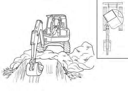
Look in the direction of rotation and make sure there are no bystanders in the work area before rotating the upperstructure [Figure OI-145]
Do not dig under the excavator [Figure OI-147]
Do not use the bucket as a breaker or pile driver. It is better to excavate hard or rocky ground after breaking it with other equipment. This will reduce damage to the excavator.
Do not move the excavator while the bucket is in the ground.
Dig only by moving the boom and arm toward the excavator.
Do not back dig (digging by moving the boom and arm away from the excavator). Damage to the attachments may occur.


Extend the arm and uncurl the bucket to dump the material into a pile or truck [Figure OI-146]
Important
Avoid operating hydraulics over relief pressure. Failure to do so will overheat hydraulic components.
OPERATING PROCEDURE (CONT’D)
Boom Swing
Swing the upperstructure, offset the boom to the right [Figure OI-148], center [Figure OI-149], and left [Figure OI-150] to dig a square hole the width of the machine without repositioning the excavator.
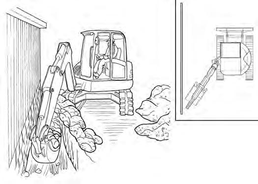

The boom offset allows the operator to dig close to buildings and other structures [Figure OI-151].

OPERATING PROCEDURE (CONT’D)
Backfilling
Figure OI-152
Use the blade to backfill the trench or hole after excavating [Figure OI-152]
Driving The Excavator
When operating on uneven ground, operate as slow as possible and avoid sudden changes in direction.
Avoid traveling over objects such as rocks, trees, stumps, etc.
When working on wet or soft ground, put planks on the ground to provide a solid base to travel on and prevent the excavator from getting stuck.
If one or both tracks have become stuck in soft or wet ground, raise one track at a time by turning the upperstructure and pushing the bucket against the ground [Figure OI-153]
Put planks under the tracks and drive the excavator to dry ground.
The bucket may also be used to pull the excavator. Raise the blade, extend the arm and lower the boom. Operate the boom and arm in a digging manner [Figure OI-154].
OPERATING PROCEDURE (CONT’D)
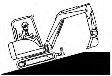
Operating On Slopes
Warning
AVOID INJURY OR DEATH
•Do not travel across or up slopes that are over 15 degrees.
•Do not travel down or back up slopes that exceed 25 degrees.
•Look in the direction of travel.
When going down a slope, control the speed with the steering levers and the speed control lever.

Warning
AVOID INJURY OR DEATH
•Avoid steep areas or banks that could break away.
•Keep boom centered and attachments as low as possible when traveling on slopes or in rough conditions. Look in the direction of travel.
•Always fasten seat belt.
W-2498-0304
Traveling
When going down grades that exceed 15 degrees, put the machine in the position shown, and run the engine slowly [Figure OI-155]
Operate as slow as possible and avoid sudden changes in lever direction.
Avoid traveling over objects such as rocks, trees, stumps, etc.
Stop the machine before moving the upper equipment controls. Never allow the blade to strike a solid object. Damage to the blade or hydraulic cylinder can result.
When traveling up slopes or on side slopes that are 15 degrees or less, position the machine as shown and run the engine slow [Figure OI-156] & [Figure OI-157]