13 minute read
FEATURES, ACCESSORIES AND ATTACHMENTS (CONT’D)

from Bobcat 442 Compact Excavator Operation & Maintenance Manual SN ADBR11001 & Above - PDF DOWNLOAD

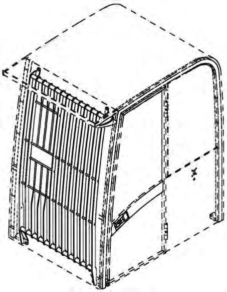
Falling Object Guards (FOGS)
Figure 4
Overhead Guard
Available for special applications that require protection from smaller objects that can fall on the cab or restrict material from entering cab openings [Figure 4] and [Figure 5].

The excavator must have the overhead guard [Figure 4] installed to meet FOGS ISO 10262 - level 1.
See your Bobcat Dealer for more information.
Special Applications Kit
Figure 5
Special Application Kit
The excavator must have the special applications kit [Figure 5] installed to meet the front guard requirements in FOGS ISO 10262 - level 1.
See your Bobcat Dealer for more information.
Special Applications Kit Inspection And Maintenance
The Special Applications Kit must be regularly inspected and maintained. Inspect the screen for damage. Replace parts as necessary.

SAFETY INSTRUCTIONS Before Operation
Carefully follow the operating and maintenance instructions in this manual.
The Bobcat excavator is highly maneuverable and compact. It is rugged and useful under a wide variety of conditions. This presents an operator with hazards associated with off highway, rough terrain applications, common with Bobcat excavator usage.
The Bobcat excavator has an internal combustion engine with resultant heat and exhaust. All exhaust gases can kill or cause illness so use the excavator with adequate ventilation.
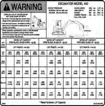
The dealer explains the capabilities and restrictions of the Bobcat excavator and attachment for each application. The dealer demonstrates the safe operation according to Bobcat instructional materials, which are also available to operators. The dealer can also identify unsafe modifications or use of unapproved attachments. The attachments and buckets are designed for a Rated Lift Capacity. They are designed for secure fastening to the Bobcat excavator. The user must check with the dealer, or Bobcat literature, to determine safe loads of materials of specified densities for the machineattachment combination.
The following publications and training materials provide information on the safe use and maintenance of the Bobcat machine and attachments:
•The Delivery Report is used to assure that complete instructions have been given to the new owner and that the machine and attachment is in safe operating condition.
•The Operation & Maintenance Manual delivered with the machine or attachment gives operating information as well as routine maintenance and service procedures. It is a part of the machine and can be stored in a container provided on the machine. Replacement Operation & Maintenance Manuals can be ordered from your Bobcat dealer.
•Machine signs (decals) instruct on the safe operation and care of your Bobcat machine or attachment. The signs and their locations are shown in the Operation & Maintenance Manual. Replacement signs are available from your Bobcat dealer.
•An Operator’s Handbook is fastened to the operator cab of the excavator. It’s brief instructions are convenient to the operator. The Handbook is available from your dealer in an English edition or one of many other languages. See your Bobcat dealer for more information on translated versions.
•The AEM Safety Manual delivered with the machine gives general safety information.
•The Compact Excavator Operating Training Course is available through your Bobcat dealer. This course is intended to provide rules and practices of correct operation of the Bobcat excavator. The course is available in English and Spanish versions.
•Service Safety Training Courses are available from your Bobcat dealer. They provide information for safe and correct service procedures.
•See the PUBLICATIONS AND TRAINING RESOURCES Page in this manual or your Bobcat dealer for Service and Parts Manuals, printed materials, videos, or training courses available. Also check the Bobcat web sites www.training.bobcat.com or www.bobcat.com
The dealer and owner / operator review the recommended uses of the product when delivered. If the owner / operator will be using the machine for a different application(s) he or she must ask the dealer for recommendations on the new use.
SAFETY INSTRUCTIONS (CONT’D)
Safe Operation Is The Operator’s Responsibility
Safety Alert Symbol
This symbol with a warning statement means: “Warning, be alert! Your safety is involved!” Carefully read the message that follows.
Warning
Operator must have instructions before running the machine. Untrained operators can cause injury or death.
W-2001-1285
Important
This notice identifies procedures which must be followed to avoid damage to the machine.
I-2019-0284
Danger
The signal word DANGER on the machine and in the manuals indicates a hazardous situation which, if not avoided, will result in death or serious injury.
D-1002-1107
Warning
The signal word WARNING on the machine and in the manuals indicates a potentially hazardous situation which, if not avoided, could result in death or serious injury.
W-2044-1107
The Bobcat excavator and attachment must be in good operating condition before use.
Check all of the items on the Bobcat Service Schedule Decal under the 8-10 hour column or as shown in the Operation & Maintenance Manual.
Safe Operation Needs A Qualified Operator
For an operator to be qualified, he or she must not use drugs or alcoholic drinks which impair alertness or coordination while working. An operator who is taking prescription drugs must get medical advice to determine if he or she can safely operate a machine.
A Qualified Operator Must Do The Following:
Understand the Written Instructions, Rules and Regulations
•The written instructions from Bobcat Company include the Delivery Report, Operation & Maintenance Manual, Operator’s Handbook, Safety Manual and machine signs (decals).
•Check the rules and regulations at your location. The rules may include an employer’s work safety requirements. Regulations may apply to local driving requirements or use of a Slow Moving Vehicle (SMV) emblem. Regulations may identify a hazard such as a utility line.
Have Training with Actual Operation
•Operator training must consist of a demonstration and verbal instruction. This training is given by your Bobcat dealer before the product is delivered.
•The new operator must start in an area without bystanders and use all the controls until he or she can operate the machine and attachment safely under all conditions of the work area. Always fasten seat belt before operating.
•Operator Training Courses are available from your Bobcat dealer in English and Spanish. They provide information for safe and efficient equipment operation. Safety videos are also available.
•Service Safety Training Courses are available from your Bobcat dealer. They provide information for safe and correct service procedures.
Know the Work Conditions
•Know the weight of the materials being handled. Avoid exceeding the Rated Lift Capacity of the machine. Material which is very dense will be heavier than the same volume of less dense material. Reduce the size of load if handling dense material.
•The operator must know any prohibited uses or work areas, for example, he or she needs to know about excessive slopes.
•Know the location of any underground lines. Call local utilities or the TOLL FREE phone number found in the Before Operation Section of this manual.
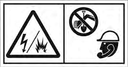
•Wear tight fitting clothing. Always wear safety glasses when doing maintenance or service. Safety glasses, respiratory equipment, hearing protection or Special Applications Kits are required for some work. See your Bobcat dealer about Bobcat Safety Equipment for your model. SI
SAFETY INSTRUCTIONS (CONT’D)
Avoid Silica Dust
Cutting or drilling concrete containing sand or rock containing quartz may result in exposure to silica dust. Do not exceed Permissible Exposure Limits (PEL) to silica dust as determined by OSHA or other job site Rules and Regulations. Use a respirator, water spray or other means to control dust. Silica dust can cause lung disease and is known to the state of California to cause cancer.
Fire Prevention
Maintenance
The machine and some attachments have components that are at high temperatures under normal operating conditions. The primary source of high temperatures is the engine and exhaust system. The electrical system, if damaged or incorrectly maintained, can be a source of arcs or sparks.
Flammable debris (leaves, straw, etc.) must be removed regularly. If flammable debris is allowed to accumulate, it can cause a fire hazard. Clean often to avoid this accumulation. Flammable debris in the engine compartment is a potential fire hazard.
The operator’s area, engine compartment and engine cooling system must be inspected every day and cleaned if necessary to prevent fire hazards and overheating.
All fuels, most lubricants and some coolants mixtures are flammable. Flammable fluids that are leaking or spilled onto hot surfaces or onto electrical components can cause a fire.
Operation
Do not use the machine where exhaust, arcs, sparks or hot components can contact flammable material, explosive dust or gases.
Electrical
Check all electrical wiring and connections for damage. Keep the battery terminals clean and tight. Repair or replace any damaged part or wires that are loose or frayed.
Battery gas can explode and cause serious injury. Use the procedure in the Operation & Maintenance Manual for connecting the battery and for jump starting. Do not jump start or charge a frozen or damaged battery. Keep any open flames or sparks away from batteries. Do not smoke in battery charging area. SI EXC-0208
FIRE PREVENTION (CONT’D)
Hydraulic System
Check hydraulic tubes, hoses and fittings for damage and leakage. Never use open flame or bare skin to check for leaks. Hydraulic tubes and hoses must be properly routed and have adequate support and secure clamps. Tighten or replace any parts that show leakage.
Always clean fluid spills. Do not use gasoline or diesel fuel for cleaning parts. Use commercial nonflammable solvents.
Fueling
Stop the engine and let it cool before adding fuel. No smoking! Do not refuel a machine near open flames or sparks. Fill the fuel tank outdoors.
Starting
Do not use ether or starting fluids on any engine that has glow plugs. These starting aids can cause explosion and injure you or bystanders.
Use the procedure in the Operation & Maintenance Manual for connecting the battery and for jump starting.
Spark Arrestor Exhaust System
The spark arrestor exhaust system is designed to control the emission of hot particles from the engine and exhaust system, but the muffler and the exhaust gases are still hot.
Check the spark arrestor exhaust system regularly to make sure it is maintained and working properly. Use the procedure in the Operation & Maintenance Manual for cleaning the spark arrestor muffler (if equipped).
Welding And Grinding
Always clean the machine and attachment, disconnect the battery, and disconnect the wiring from the Bobcat controllers before welding. Cover rubber hoses, battery and all other flammable parts. Keep a fire extinguisher near the machine when welding.
Have good ventilation when grinding or welding painted parts. Wear dust mask when grinding painted parts. Toxic dust or gas can be produced.
Dust generated from repairing nonmetallic parts such as hoods, fenders or covers can be flammable or explosive. Repair such components in a well ventilated area away from open flames or sparks.
Fire Extinguishers
Know where fire extinguishers and first aid kits are located and how to use them. Inspect the fire extinguisher and service the fire extinguisher regularly. Obey the recommendations on the instructions plate.
MACHINE SIGNS (DECALS)
Follow the instructions on all the Machine Signs (Decals) that are on the excavator. Replace any damaged machine signs and be sure they are in the correct locations. Machine signs are available from your Bobcat Excavator dealer.
MACHINE SIGNS (DECALS) (CONT’D)
Follow the instructions on all the Machine Signs (Decals) that are on the excavator. Replace any damaged machine signs and be sure they are in the correct locations. Machine signs are available from your Bobcat Excavator dealer.
Publications And Training Materials
The following publications are also available for your Bobcat Excavator. You can order them from your Bobcat dealer.
For the latest information on Bobcat products and the Bobcat Company, visit our web site at www.bobcat.com; you can also order Operator and Service Training materials online through www.bobcatstore.com
OPERATION & MAINTENANCE MANUAL
6987203
- Complete instructions on the correct operation and the routine maintenance of the Bobcat Excavator.
SERVICE MANUAL

6987204
- Complete maintenance instructions for your Bobcat Excavator.
SAFETY MANUAL
6570354
- Provide basic safety procedures and warnings for your Bobcat Excavator
OPERATOR’S HANDBOOK
6901803
- Gives basic operation instructions and safety warnings.
COMPACT EXCAVATOR OPERATOR TRAINING COURSE
6903186
- Introduces operator to step-by-step basics of Compact Excavator operation.
EXCAVATOR SERVICE SAFETY COURSE
6900916
- Introduces Service Technicians to step-by-step basics of proper and safe excavator maintenance and servicing procedures.
OPERATOR SAFETY VIDEO
6903181
- Provides basic safety instructions.
OPERATOR SAFETY DVD
6904762
Provides basic safety instructions contained in all Bobcat Safety Videos in both English and Spanish.

Instruments And Consoles
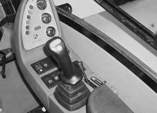
Left Console
Figure OI-1
Left Control Lever (Joystick) - (Item 1) [Figure OI-1] (See HYDRAULIC CONTROLS on Page OI-16.)
Upperstructure Swing Brake - (Item 2) [Figure OI-1] Press the button on the control lever to assist in stopping the upperstructure swing function. (See Upperstructure Slew Brake on Page OI-23.)
Switch - (Item 3) [Figure OI-1] Not used for this model.
Switch - (Item 4) [Figure OI-1] Not used for this model.
Arm Rest (Adjustable) - (Item 5) [Figure OI-1]
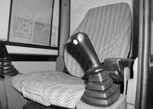

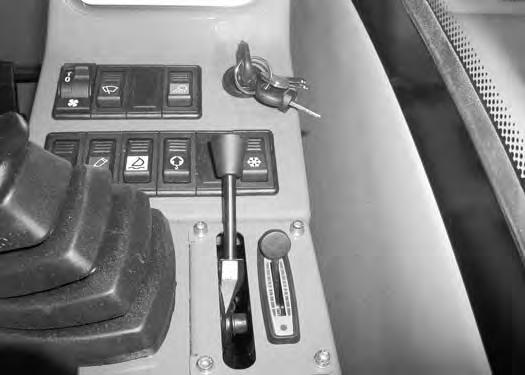
Figure OI-2
Switch - (Item 1) [Figure OI-2]. Not used for this model.
Battery Disconnect Switch - (Item 1) [Figure OI-3] Turn the key 1/4 turn counterclockwise and remove the key to disconnect the battery from the electrical system. Install the key and turn 1/4 turn clockwise to connect the battery to the electrical system.
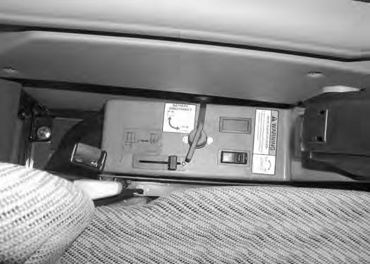
ISO/STD Selector Switch - (Item 2) [Figure OI-3] Push the switch to the rear for STD operation (the switch is illuminated). Push the switch to the front for ISO operation (the switch is not illuminated).
(Item 3) [Figure OI-3]. Not used for this model.
INSTRUMENTS AND CONSOLES (CONT’D)
Right Console
Figure OI-4
Right Control Lever (Joystick) - (Item 1) [Figure OI-4] (See HYDRAULIC CONTROLS on Page OI-16.)


Horn - (Item 2) [Figure OI-4] Press the button on the control lever to sound the horn.
Momentary Hydraulic Switch - (Item 3) [Figure OI-4] (See HYDRAULIC CONTROLS on Page OI-16.)
Momentary Hydraulic Switch - (Item 4) [Figure OI-4] (See HYDRAULIC CONTROLS on Page OI-16.)
Figure OI-5
Boom Load Indicator - (Item 1) [Figure OI-6]. Shows load on boom cylinder circuit when lifting.
Engine Temperature Gauge - (Item 2) [Figure OI-6]. Shows the engine coolant temperature.
Fuel Gauge - (Item 3) [Figure OI-6]. Shows the amount of fuel in the tank.
Hourmeter - (Item 4) [Figure OI-6]. Displays the total operating hours on the excavator.
Battery Charge Indicator - (Item 5) [Figure OI-6]. Light will illuminate when the voltage is out of range.
Air Intake Heater - (Item 6) [Figure OI-6]. Light will illuminate when the air intake heater is energized.
Engine Oil Pressure Indicator - (Item 7) [Figure OI-6] Light will illuminate when the engine oil pressure is low.
Air Filter Indicator - (Item 8) [Figure OI-6]. Light will illuminate when the air flow becomes restricted.
Hydraulic Oil Filter Indicator - (Item 9) [Figure OI-6]. Light will illuminate when the hydraulic oil filter is becoming plugged.
Hydraulic Oil Level Indicator - (Item 10) [Figure OI-6] Light will illuminate when the hydraulic oil level in the tank is low.
Start / Run Switch - (Item 11) [Figure OI-6]. Starts and stops the excavator engine.
Switch - (Item 1) [Figure OI-5]. Not used for this model.
Arm Rest (Adjustable) - (Item 2) [Figure OI-5].
INSTRUMENTS AND CONSOLES (CONT’D)
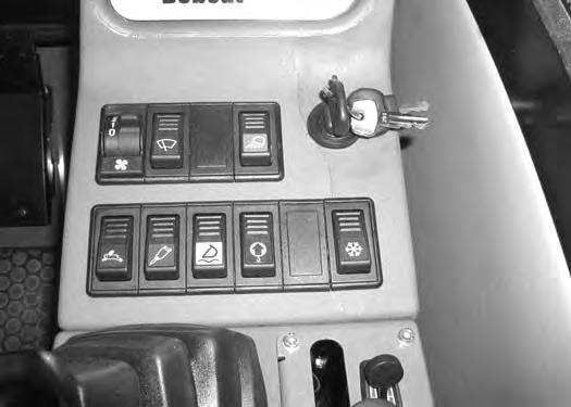
Right Console (Cont’d)
Figure OI-7
Heater Fan Switch - (Item 1) [Figure OI-7]. Three speed fan motor control.
Wiper/Washer Switch - (Item 2) [Figure OI-7]. Starts and stops the wiper motor. Press and hold the bottom of the switch to activate the washer.
Rotating Beacon (If equipped) - (Item 3) [Figure OI-7]
Light Switch - (Item 4) [Figure OI-7]. Press the switch to turn on the cab/boom work light.
Two Speed Travel Control Switch - (Item 1) [Figure OI8]. Engages and disengages high range travel speed. (The switch will be illuminated in high range.)
Auxiliary Hydraulic Mode Switch - (Item 2) [Figure OI8]. Press this switch when using the hydraulic breaker. (The switch will be illuminated.)
Float Switch - (Item 3) [Figure OI-8]. Press this switch to put the blade in the float position. (The switch will be illuminated.)
Overload Warning Switch - (Item 4) [Figure OI-8] Press this switch to engage the overload warning alarm. (The switch will be illuminated.) The warning alarm will sound when the boom/arm/bucket functions are being overloaded.
Motion Alarm (If equipped) - (Item 5) [Figure OI-8]
(Item 6) [Figure OI-8]. Not used for this model.
Engine Speed Control Lever - (Item 7) [Figure OI-8] Controls the RPM of the engine. Push the lever forward for low speed. Pull the lever back to increase engine speed.
Temperature Control Lever - (Item 8) [Figure OI-8] Push the lever forward to increase the cab temperatures; backward to decrease temperature.
INSTRUMENTS AND CONSOLES (CONT’D)
Right Console (Cont’d)
Figure OI-9
Air Conditioning / Fan Motor Switch - (Item 1) [Figure OI-9]. Turns on the air conditioning; three speed fan switch.
Air Conditioning Temperature Control - (Item 2) [Figure OI-9]. Turn the switch clockwise to decrease cab temperatures, counterclockwise to increase cab temperatures.

Raising And Lowering The Left Console
Raise the console before exiting the cab.
Figure OI-11
Auxiliary Power Outlet - (Item 1) [Figure OI-10] - 12 volt.
Pull up on the handle (Item 1) [Figure OI-11]. The lift spring will assist in raising the console.

Lower the console before operating the excavator.
Push down on the handle (Item 1) [Figure OI-11] until the console is in the down position.
NOTE: When the console is raised, the hydraulic and traction systems are locked and will not operate.

OPERATOR CAB Description
The excavator has an operator cab as standard equipment.
Warning
Never modify operator cab by welding, grinding, drilling holes or adding attachments unless instructed to do so by Bobcat Company. Changes to the cab can cause loss of operator protection from rollover and falling objects, and result in injury or death.
W-2069-0200
Cab Door
The start key can be used to lock the cab door. Push the door all the way open until the latch engages to hold the door in the open position.
OPERATOR CAB (CONT’D)
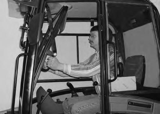

Front Window
Opening The Front Window
NOTE: The right hand latch is shown. The procedure is the same for both latches.

OPERATOR CAB (CONT’D)
Front Window (Cont’d)
Figure OI-17
Turn the two latches (Item 1) [Figure OI-17] to the locked position.
Closing The Front Window
Rotate the two latches (Item 1) [Figure OI-18] to the unlocked position.
Use both window grab handles to pull the window down [Figure OI-18]
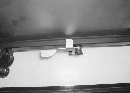
Rotate the two latches (Item 1) [Figure OI-19] to the locked position.


Front Window Ventilation
The front window may be opened approximately 4 in. (181 mm).

OPERATOR CAB (CONT’D)
Right Side Windows
Opening the right side window


OPERATOR CAB (CONT’D)
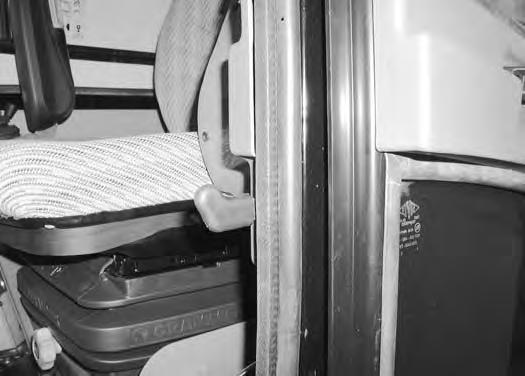
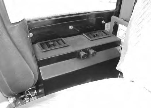
Heating, Ventilation And Air Conditioning Duct

The cab fresh air vent is located behind the operators seat.

Move the lever (Item 1) [Figure OI-23] to the right to close the vent.

Move the lever (Item 1) [Figure OI-23] to the left to open the vent.
heat
There are two air conditioning ducts (Item 1) [Figure OI26]
Turn the vents to direct air as desired.