3 minute read
Removing and installing the fuel control system


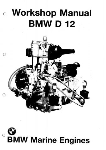
Fig. 89 Disengage the two circlips (89/1) and pull the rocker lever shaft (89/2) out of the rocker levers (89/3) and out of the rocker lever bracket (89/4). Pay attention to the shim(s) (89/5). Examine the rocker levers for wear and exchange, if necessary.
Installing the rocker levers Installation takes place in the reverse sequence to removal.
Note: Fit the rocker lever shaft with the longer ridge facing the crankcase. Tighten the socket-head screw (89/6) with a tightening torque of 60 Nm. — Install the camshaft assembly 89
REMOVING AND INSTALLING THE FUEL CONTROL SYSTEM
Removing the fuel control system
— Remove the camshaft assembly — Remove the rocker levers
Fig. 90
Shift the control lever to the “Stop” position and remove the circlip (90/1) from the governor lever shaft.
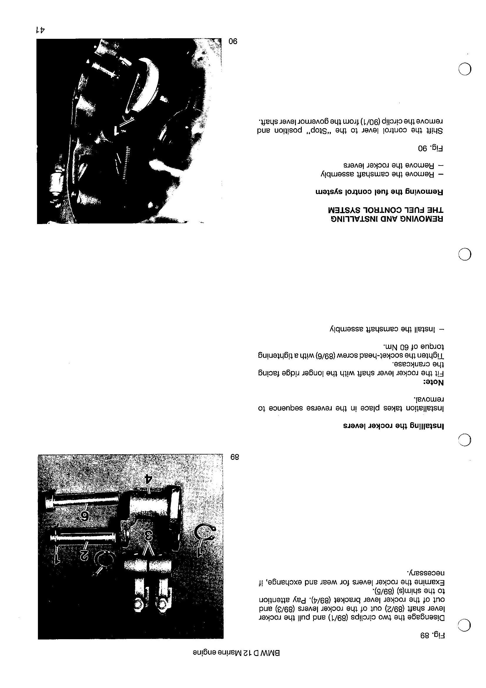
Fig. 91 Use the extractor, special tool No. 74 64 1 333 554, to pull the governor lever shaft out of the governor lever (91/1) and out of the crankcase.. Disengage the governor lever from the governor spring and take it out of the crankcase.
Fig. 92 Block the crankshaft. Use the extractor, special tool No.7464 1 333 527, to pull the crankshaft gear (92/1) off the crankshaft. Remove the sliding disc (92/2) and ball sleeve (92/3), paying attention to balls falling out of the ball hub. 91
Fig. 93 Use the extractor, special tool No. 74 64 1 333 557, to pull the ball hub off the crankshaft. 92
Fig. 94 Unscrew the lock nut (94/1) and hex. nut (94/2) and take the washer (94/3) offthe control lever shaft (94/4). Remove the control lever (94/5).
Fig. 95 Take the key (95/1) out of the shaft and remove the spacer (95/2). Sever the locking wire and screw out the speed adjusting screw (95/3). Knock the control lever shaft out of the crankcase. 94
Fig. 96 Remove the cotter pin (96/1) and take the spring (96/2) off the control lever shaft (96/3). Exchange the 0-ring (96/4). 95
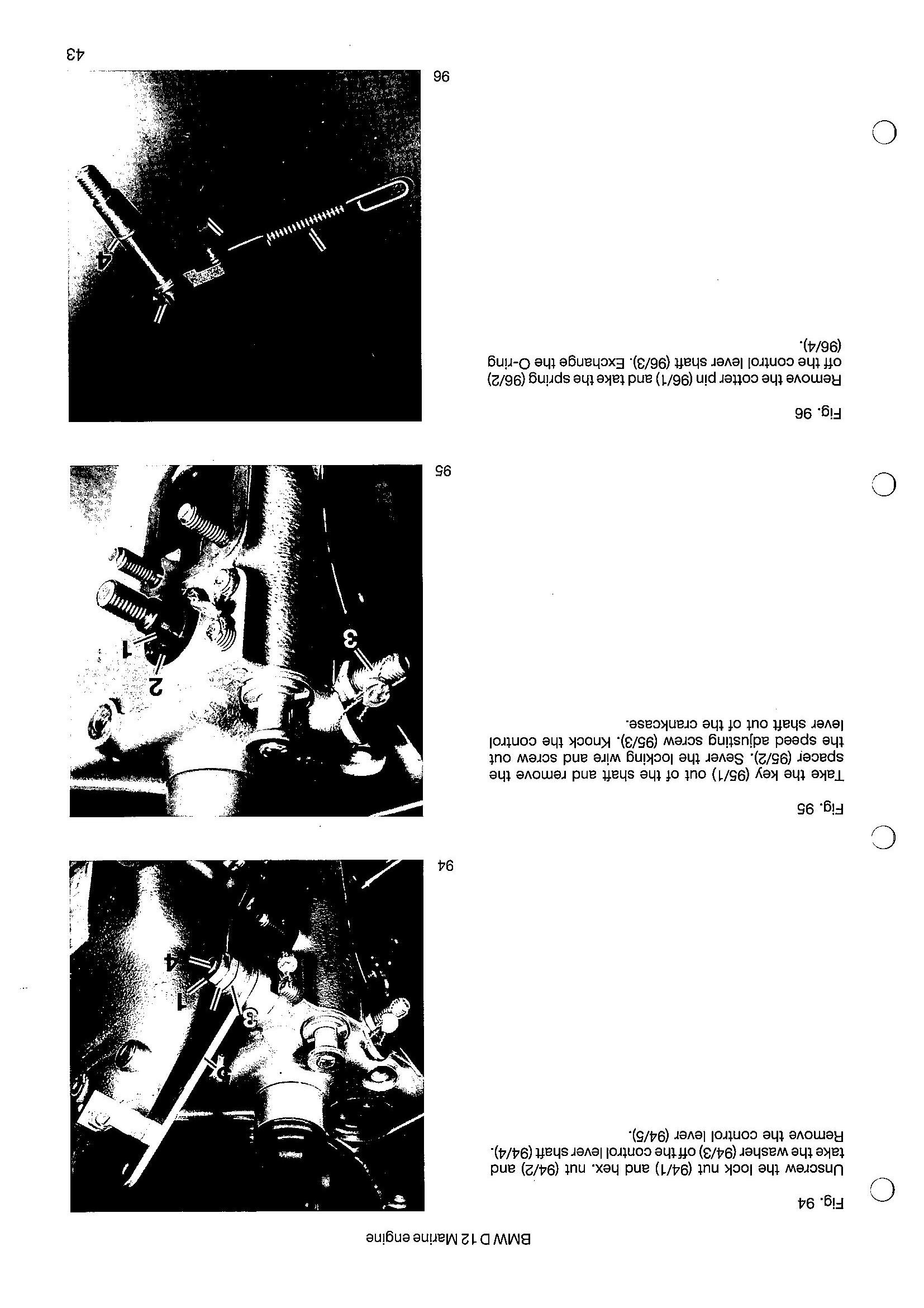
Fig. 97 Sever the locking wire, screw the headless screws out of the holes (97/1) and use the special wrench, special tool No. 74 64 1 333 528, to screw out the cold start device (97/2).
Installing the fuel control system Installation of the fuel control system takes place in the reverse sequence to removal.
Note: Fig. 98 Heat both parts (98/1) of the ball hub to 70—80° C, place them on the crankshaft and use the mandrel, special tool No. 7464 1 333 525, to drive them on the crankshaft as far as they will go. Use some bearing grease to fit the four balls diagonally into the ball hub. Push on the ball sleeve and sliding disc (see Fig. 92) and check that they slide properly.
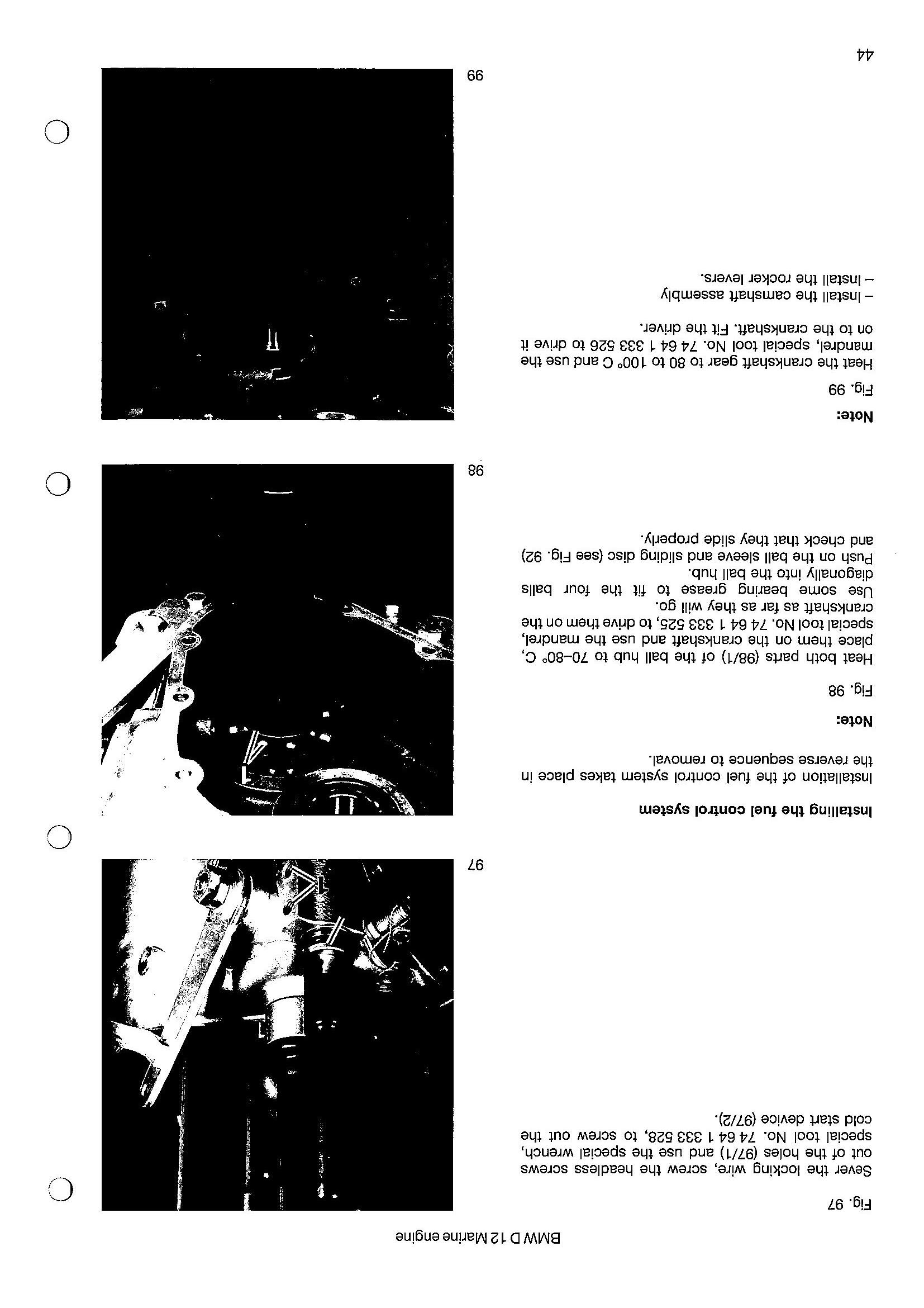
Note: Fig. 99 Heat the crankshaft gear to 80 to 1000 C and use the mandrel, special tool No. 74 64 1 333 526 to drive it on to the crankshaft. Fit the driver.
— Install the camshaft assembly — Install the rocker levers. 97
98
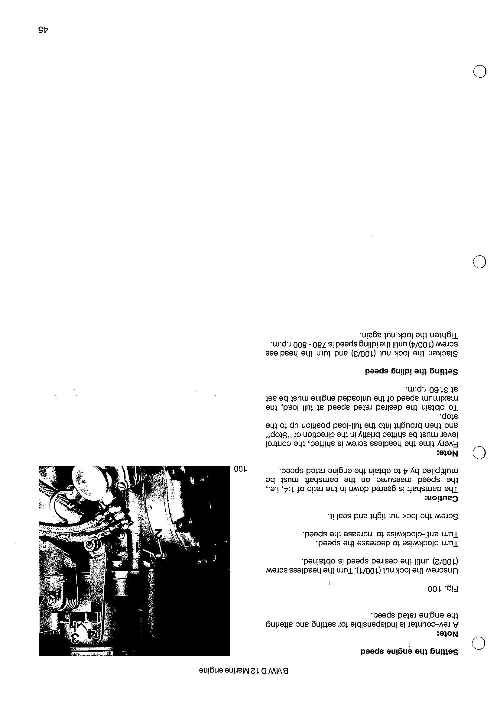
Setting the engine speed Note: A rev-counter is indispensible for setting and altering the engine rated speed.
Fig. 100 Unscrew the lock nut (100/1). Turn the headless screw (100/2) until the desired speed is obtained. Turn clockwise to decrease the speed. Turn anti-clockwise to increase the speed. Screw the lock nut tight and seal it. Caution: The camshaft is geared down in the ratio of 1:4, i.e., the speed measured on the camshaft must be multiplied by 4 to obtain the engine rated speed. Note: Every time the headless screw is shifted, the control lever must be shifted briefly in the direction of “Stop” and then brought into the full-load position up to the stop. To obtain the desired rated speed at full load, the maximum speed of the unloaded engine must be set at 3160 r.p.m. Setting the idling speed Slacken the lock nut (100/3) and turn the headless screw (100/4) until the idling speed is 780-800 r.p.m. Tighten the lock nut again.