3 minute read
Removing and installing the injection pump Removing and installing the piston


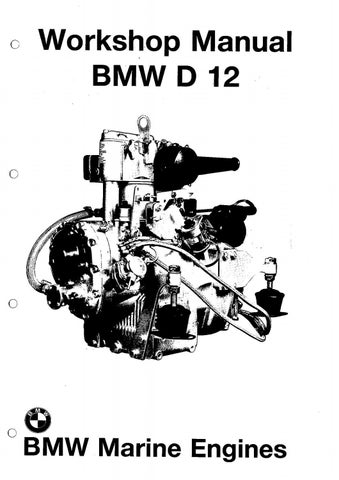
Removing the piston Fig. 101 Bring the piston to T.D.C. and disengage the circlips (101/1).
Fig. 102 Heat the piston to 50° C, use the extractor, special tool No. 7464 1 333 552, to press the gudgeon pin out and remove the piston from the connecting rod. 101
I
Fig. 103 Remove the piston rings from the piston with piston ring pliers, special tool No. 74 64 1 333 549. Examine the piston for damage such as ring land fracture, seizure sites, worn ring grooves, worn gudgeon-pin bores and exchange, if necessary. 102
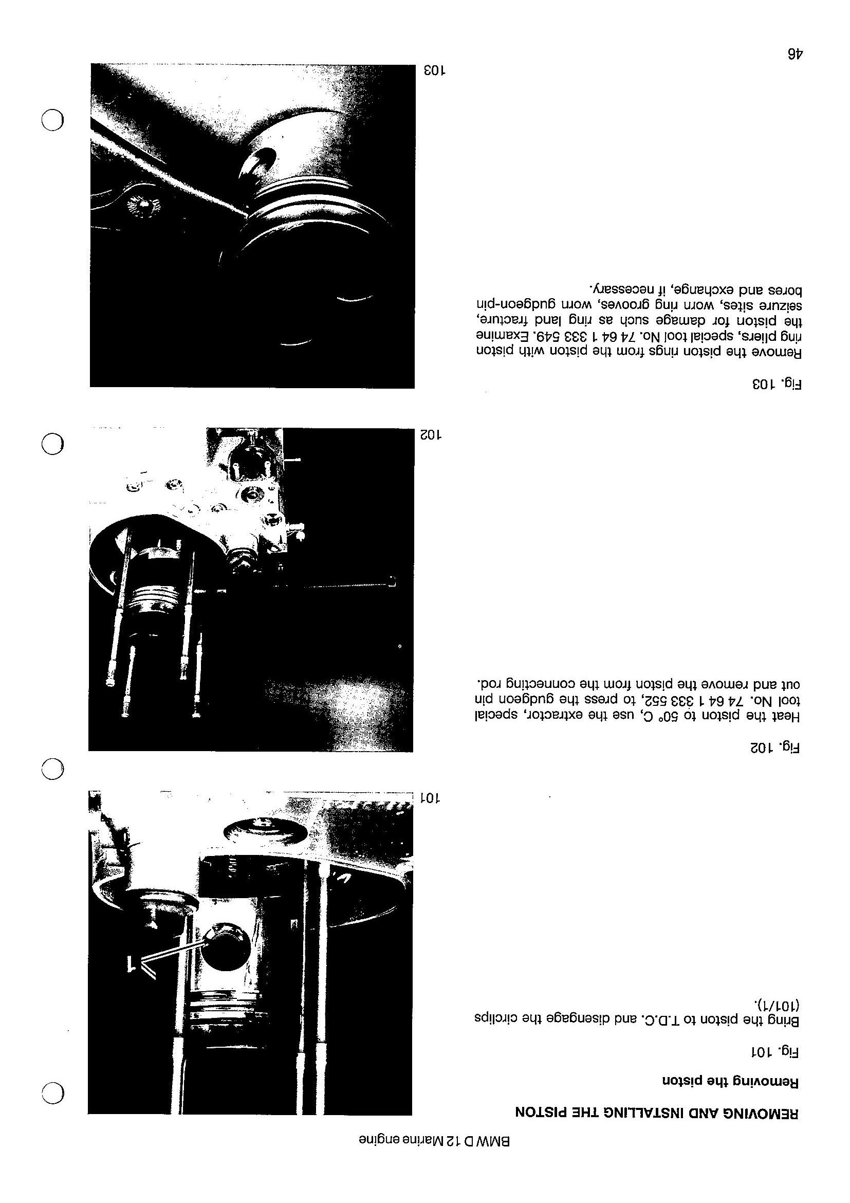
Fig. 104 Fit a piston ring (104/1) in the cylinder and measure the piston ring gap with a feeler gauge. Specified gap (new condition) 0,3 — 0,5 mm. Permissible wear up to 2,0 mm.
Carry out this measurement one after another. on all three piston rings,
Installing the piston Installation of the piston takes place in the reverse sequence to removal.
Caution: Fig. 105 The recess (105/1) in the piston top flywheel side. must face the
Note: Before the gudgeon pin (105/2) is installed, fit a circlip in the piston as a stop. — Install the cylinder — Install the cylinder head
REMOVING AND INSTALLING THE CONNECTING ROD
Removing the connecting rod
Fig. 106 Place the engine on one of its sides. Screw out the four hex.-head screws (106/1), remove them together with their spring washers and take off the crankcase cover (106/2). Pull out the oil dipstick. 104
105
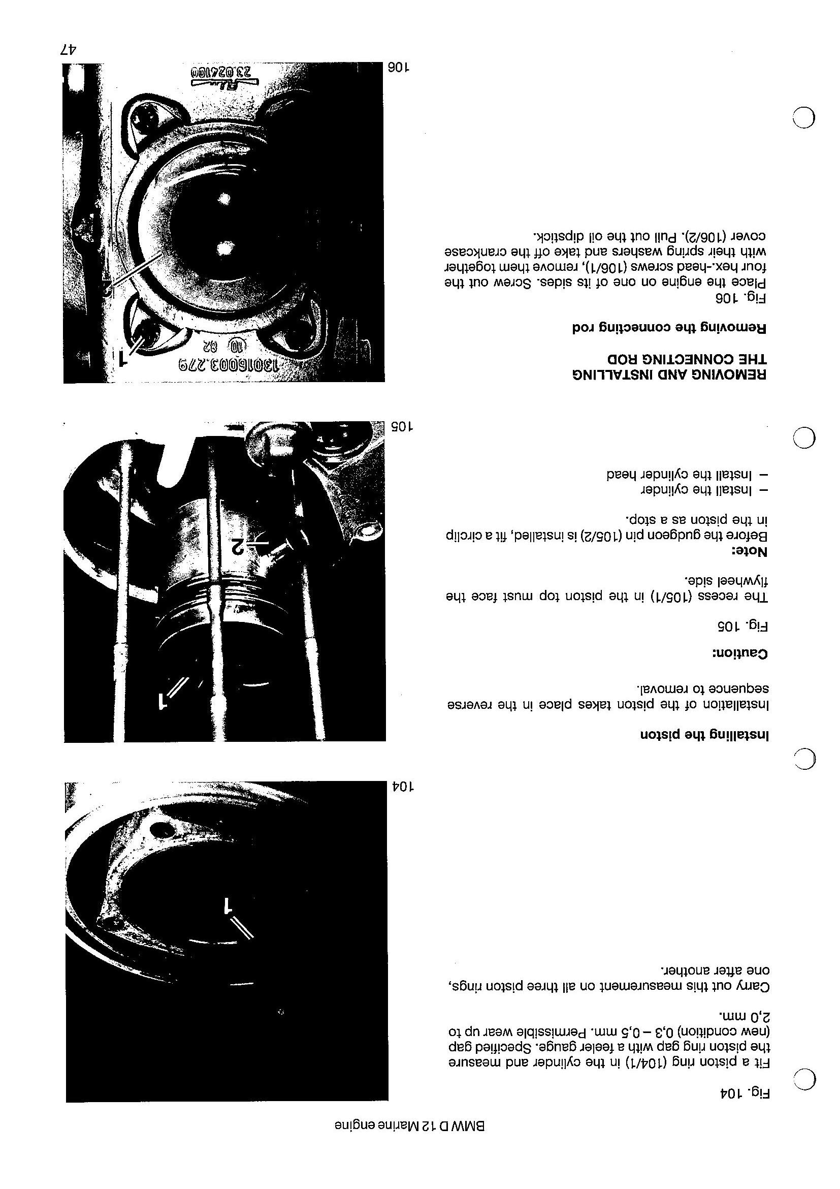
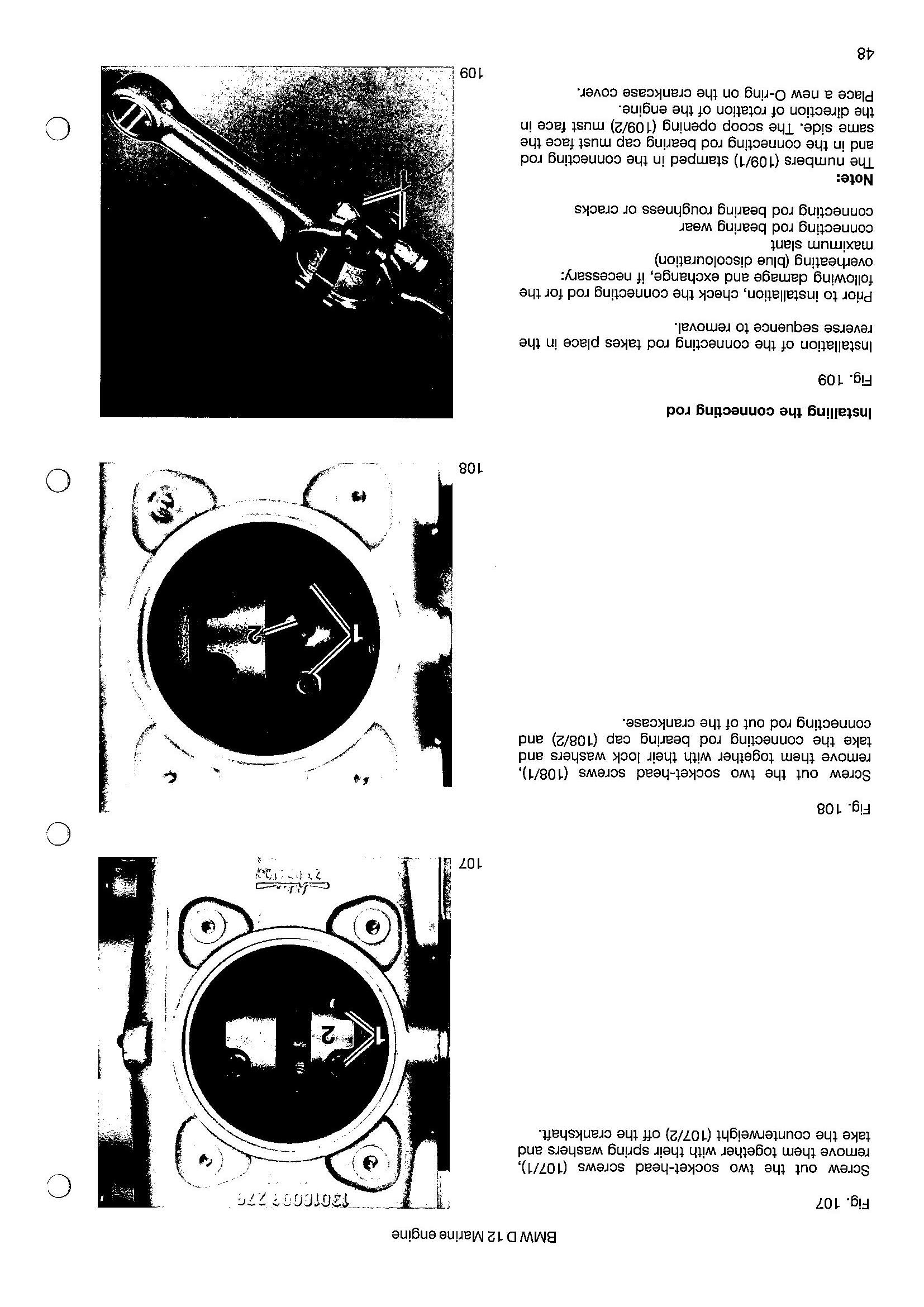
Fig. 107 Screw out the two socket-head screws (107/1), remove them together with their spring washers and take the counterweight (107/2) off the crankshaft.
Fig. 108 Screw out the two socket-head screws (108/1), remove them together with their lock washers and take the connecting rod bearing cap (108/2) and connecting rod out of the crankcase. 107
Installing the connecting rod Fig. 109 Installation of the connecting rod takes place in the reverse sequence to removal. Prior to installation, check the connecting rod for the following damage and exchange, if necessary: overheating (blue discolouration) maximum slant connecting rod bearing wear connecting rod bearing roughness or cracks Note: The numbers (109/1) stamped in the connecting rod and in the connecting rod bearing cap must face the same side. The scoop opening (109/2) must face in the direction of rotation of the engine. Place a new 0-ring on the crankcase cover. 108
REMOVINGAND INSTALLING THE CRANKSHAFT
Removing the crankshaft
— Remove the connecting rod
Fig. 110
Remove the second counterweight (see Fig. 107). Place the engine upright again and take the crankshaft out of the crankcase, if necessary using a plastic hammer to drive it out. Disengage the snap ring (11 0/ 1) and press out the outer race (110/2) of the cylindrical roller bearing. Heat the crankcase to approx. 80CC and pull out the camshaft bearing (110/ 3) with the internal extractor, special tool No. 7464 1 333 530.
110
Fig. 111
Remove the shim (111/1), heat the two inner races (111/2) to approx. 90—i 000 C and take them off the crankshaft.
Note: Heat the inner races with a medium-size welding torch to avoid heat being transferred to the crankshaft. Pay attention that the races are not overheated (blue discolouration). Under no circumstances must damaged races be re-used.
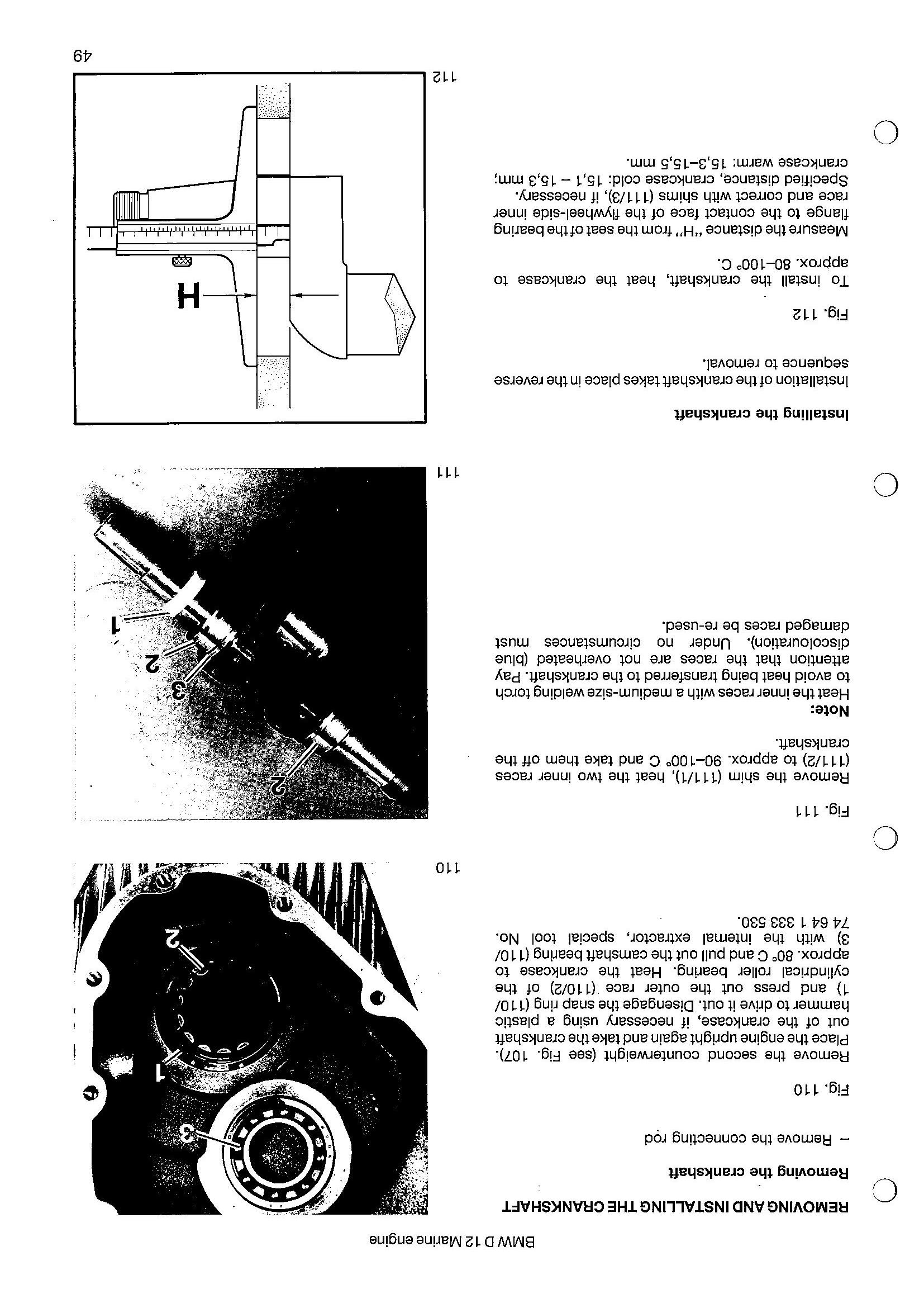
Installing the crankshaft Installation of the crankshaft takes place in the reverse sequence to removal.
Fig. 112 To install the crankshaft, heat the crankcase to approx. 80—100° C. Measure the distance “H” from the seat ofthe bearing flange to the contact face of the flywheel-side inner race and correct with shims (111/3), if necessary. Specified distance, crankcase cold: 15,1 — 15,3 mm; crankcase warm: 15,3—15,5 mm.
111