Yachts and Launches with Heat Exchanger Cooling It is essential that a 33% to 50% anti-freeze/water mixture is used. This not only stops freezing up in winter, but it prevents overheating and corrosion. The warranty is invalid unless the correct ratio is used. Concentration of ethylene should not exceed 50%. The anti-freeze in the fresh water system enables the boiling point of water to rise to 124°C with a 13 psi pressure cap fitted. The water temperature alarm switch will however be activated at 95° to 100°C. If no anti-freeze or a very weak solution is used, then the water temperature switch may not be activated before coolant is lost.
SEA WATER PUMP AND COOLING SYSTEM (Heat exchanger-cooled engines) CAUTION Before working on the sea water system ensure that the sea cock is in the off position. (1) It is very important that the correct sea water flow is maintained to cool the closed circuit system of the engine. The key component in this system is the sea water pump impeller. This should be checked every year by removing the circular plate (see fig. 2h). (2) Withdraw the rubber impeller from its drive shaft as shown. See diagram 2i. (3) Check impeller for cracks in the rubber, excessive wear or lost vanes. Replace with a new impeller as necessary.
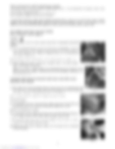
Fig. 2h
Note: If any pieces of rubber impeller are missing then they must be found as they are most likely to be trapped in the entrance to the heat exchanger cooling stack. See ‘Cleaning Tube Stack’.
CLEANING THE HEAT EXCHANGER TUBE STACK AND REPLACING WASTING ZINC ANODE (1) The wasting zinc anode should be checked every six months and replaced every year or as necessary. The anode is attached to the bolt inserted in the end cap of the heat exchanger. See Fig 2j. On most engines this is on the aft end.
Fig. 2I
(2) Unscrew the bolt and replace the complete unit with a new one. (3) Check for leaks. (4) It is possible for fine sea weed and other debris to get past the inlet filter and into the tube stack. This should be removed and cleaned. See fig. 2k. (5) Drain off coolant into a bucket. (6) Unscrew the 2 end cap retaining bolts (one each end of the tube stack). Remove the ‘O’ rings and pull out tube stack. Clean tube stack and end caps.
Zinc Anode
Fig. 2j
(7) Re-assemble using new ‘O’ rings. Do not overtighten end cap bolts and make sure the tube stack is the right way round. (8) Re-fill engine with water/anti-freeze solution and run engine up to temperature to check for leaks.
Fig. 2k 10
Downloaded from www.Manualslib.com manuals search engine


