19 minute read
Troubleshooting


TROUBLE SHOOTING Beta diesels are very reliable if installed and serviced correctly, but problems can occur and the following list gives the most common ones and their solution.
Problem: Engine does not start but starter motor turns over OK
Possible Cause Solution No fuel: Turn fuel cock on and fill tank. Air in fuel system: Vent air (see initial start-up) Water in fuel: Change fuel filter and bleed system. Blocked fuel pipe: Clean out and bleed system. Fuel filter clogged: Change filter and bleed system. Fuel lift pump blocked: Remove and replace. Blocked injector: Remove and clean. Fuel return not fed back to the tank: Re-route fuel return pipe. Heater plugs not working: Check wiring to the plugs, and replace plugs if they are burnt out. Stop solenoid stuck in off position: Check solenoid is free to return to run position.
Problem: Starter motor will not turn or turns over very slowly
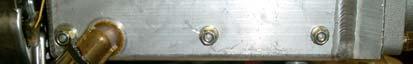
Possible Cause Solution Battery discharged: Charge battery or replace. Check alternator belt tension. Starter motor flooded with sea water: Remove and clean or replace. Wiring disconnected or loose: Check circuit for loose connections. Water in cylinders: Incorrect installation. This is serious – check engine oil for signs of water (creamy-coloured oil). Ring your dealer. Engine harness fuse blown: Replace fuse (located by starter motor or above flywheel housing) and check for wiring faults
FUSE (If located by starter motor, usually it is positioned above flywheel housing at rear of engine)
Note: For convenience, some engines are supplied with a spare fuse and holder attached to the main engine fuse holder.
Problem: Erratic running Possible Cause Solution Air in fuel supply: Check supply system for leaks and fix. Fuel lift pump faulty: Replace. Clogged fuel filter: Replace. Fuel return not fed back to the fuel tank, or blocked pipe: Re-route pipe or clean. Air filter blocked: Replace. Worn or blocked injector: Service injectors. Engine rpm in gear is too low, this must be 850 min: Increase engine tick over speed. Faulty stop solenoid: Disconnect wiring to solenoid. If running improves check for a wiring fault.
Broken fuel injection pump spring: Replace. Problem: White or blue exhaust gas Possible Cause Solution Engine oil level too high: Reduce the level. Blocked injector: Service injectors. Piston ring and bore worn, giving a low compression: Get compression checked by your dealer or Kubota service agent. He will advise action to be taken.
Check that the breather pipe is clear and not obstructed: Remove and clean out Problem: Black exhaust gas Possible Cause Solution Blocked air filter element Inspect and replace Over pitched propeller – engine will not reach its full rpm: Get the propeller re-pitched if necessary. Accumulated debris on hull Inspect and clean if required Problem: Low power output Possible Cause Solution Propeller is too big: Change or depitch. Check gearbox reduction ratio relative to propeller size: Change. Blocked fuel filter: Replace. Blocked air filter: Replace. Air in fuel system: Check system. Governor spring incorrectly mounted: Dealer to adjust. Single lever control not operating correctly: Disconnect speed control cable and move the lever by hand. Adjust cable.
The electrical load is too large on start up: Disconnect or reduce the load.
Problem: High oil consumption Possible Cause Solution Oil leaks: Check for leaks. Piston rings worn: Overhaul required. Valve stem and guide worn: Overhaul required. Piston rings gap facing the same direction: Shift ring gap position.
Problem: Water in lubricating oil (heat exchanger cooled) Possible Cause Solution Oil goes "milky" due to seawater entering exhaust manifold: Check installation - has anti-siphon valve been fitted? Change engine oil and run engine for 10 minutes each time to eliminate any water. Get fuel injection pump and compression checked by Service Agent.
Problem: Water in lubricating oil (general) Possible Cause Solution Core plug pushed out due to frozen block: Service Agent to check and replace. Water pump seal damaged: Service Agent to check and replace.
Problem: Water in lubricating oil (keel cooled) Possible Cause Solution Oil goes "milky" due to water Check installation - has dry exhaust system been fitted correctly, entering exhaust manifold andensuring rain water cannot enter the exhaust port and run back? then into the sump: (See DRY EXHAUST SYSTEM) Change engine oil and run engine for 10 minutes each time to eliminate any water. Get injection pump checked by Service Agent.
Problem: Low oil pressure warning light comes on when engine speed reduced to tick over: Possible Cause Solution Faulty switch sender: Replace. Engine running too hot: Check cooling water flow (see section 2 Cooling). Oil relief valve stuck partially open with dirt: Remove and clean. Blocked oil filter: Change. Wiring fault: Check circuit. Insufficient oil: Top up and check for leaks.
Problem: Panel rev counter not working (when fitted) Possible Cause Solution No W connection to alternator:Check output from ‘W’ connection. Should be about 9V AC Wiring fault: Check circuit
Problem: Engine overheats
Possible Cause Solution Check coolant level: Top up. Insufficient sea water flow: Clear blocked intake or filter. Damaged or worn pump impeller: Replace. Blocked tube stack in heat exchanger: Remove tube stack and clean – replace ‘O’ rings. Zinc anode flakes blocking tube stack: Remove and clean tube stack as above. Pressure cap loose: Replace. Switch sender faulty: Replace. Inlet sea cock is too small: Replace (see heat exchanger cooled seawater inlet system in section 3). High exhaust back pressure: Must not exceed 3.1" of Hg. Air locks in cooling pipe work to keel cooler: Vent the system and top up coolant. Keel cooler insufficient size: Contact boat builder
GENERAL -HEAT EXCHANGE ONLY: The most common cause of overheating is insufficient seawater flow due to a blocked intake (weed or a plastic bag!). If this happens then clear the blockage. If the problem is not cured then check the system for sea water flow which should be 15 litres / minute minimum at 1,500 rpm as follows: (a) With the boat tied up and out of gear run the engine up to 1500 rpm. *Hold a plastic bucket over the exhaust outlet for 10 seconds and measure the amount of water collected. Multiply this value by 6 to give the flow in litres/min. Repeat twice and take an average. If the flow rate is noticably less than the 15 litre per minute minimum at 1,500 rpm, then: (b) Check impeller in sea water pump - if worn replace. (c) If impeller has a vane missing then this will be lodged either in the pipe to the heat exchanger or in the end of the exchanger. This must be removed. (d) Check flow again as in (a). *Note: This operation must only be done in safe conditions, in port and with two assistants. Working from a rubber dinghy is best. The person holding the bucket should take precautions against breathing in the exhaust gasses.
Problem: Knocking noise
Possible Cause Solution Propshaft touching gearbox output coupling through split boss or Type 16 coupling: Adjust, giving correct clearance (10mm) between gearbox and propeller shaft
Flexible mount stud touching engine bed: Adjust stud to clear Drive plate broken Replace / repair Engine touching engine bed Re-align engine / modify bed
Problem: Battery quickly discharges Possible Cause Solution High load and insufficient Reduce load or increase charging time. Large domestic battery running: banks subject to high electrical loads will take a considerable time to recharge from a single alternator. Low electrolyte level: Top up. Fan belt slipping - black dust in engine compartment, engine compartment temperature too Adjust tension / replace belt with a high temperature type and / high: or improve engine compartment ventilation. Alternator defective: Check with Agent. Battery defective: Replace. Poor wiring connection: Check wiring system.
Problem: Transmission noise
Possible Cause Solution Check gearbox oil level: Top up. "Singing" propeller: Check with supplier. Drive plate rattle at tickover: Check engine rpm (must be 850 rpm minimum in gear). Worn drive plate: Change. Propeller shaft hitting the Move shaft back to give at least 5mm clearance (Type 12/16 Gearbox half coupling: couplings only) Problem: Vibration
Possible Cause Solution Poor alignment to shaft: The alignment must be accurate even if a flexible coupling is used (see section 3 ALIGNMENT).
Flexible mounts not adjusted correctly to take even weight: Check relative compression of each mount. Flexible mount rubber perished:Replace. (Diesel or oil will eventually perish most rubbers.) Loose securing nut on flexible mount: Check alignment and then tighten the nuts. Insufficient clearance betweenThere must be at least 10% tip clearance between propeller and the propeller tip and the bottombottom of the boat (ie 10% of the propeller diameter as of the boat: clearance). Refer to boatbuilder. Loose zinc anode on the shaft:Tighten or replace. Worn cutless bearing or shaft: Replace. Weak engine support/bearers:Check for cracked or broken feet. Problem: Morse control cable will not fit
Possible Cause Solution Fitting incorrectly Cables are being fitted the wrong way around, switch over and fit the opposite way.
Electrical fault finding & trouble shooting –engines built after July 2005 only The following chart is compiled to aid diagnosis of electrical faults, based on the Beta 10-90hp range of engines. If your engine was built before July 2005, contact Beta Marine for the relevant electrical trouble shooting guide. Standard sea specification engines (heat exchanger cooled) are supplied with a single alternator, mounted port side, supplying power to starter battery and control panel. Standard canal specification engines (keel cooled) are supplied with twin alternators: • 1st alternator, mounted port side, supplying power to starter battery and control panel • 2nd alternator, the standard mounting position for this is above the engine on the starboard side (or below 1st alternator on 75 & 90hp), supplying power to the domestic battery system. Both of these alternators work independently, if the domestic battery system is disconnected, the engine will still run correctly but: • Domestic charge warning lamp will not function • Warning buzzer will remain on at all times Standard control panels are supplied with four or five lamps: Four lamp panels: 2a, 2ab’V’, 2ab’V’W and 2b, these panels utilise bulbs inside sealed lamp holders Five lamp panels: 2ab’d’ and 2c’d’, these panels also utilise bulbs inside sealed lamp holders, having an additional lamp for domestic battery charge All Beta panels have the following warning lamps: (2a, 2ab’d’, 2ab’V’, 2ab’V’W, 2b, 2c’d’) Starter battery charge warning lamp Red • High engine temperature warning lamp Red • Low engine oil pressure warning lamp Red All panels also have: • Panel power on (this is not a warning lamp) Green In addition to above the domestic panels also have: (2ab’d’, 2c’d’ only) • Domestic battery charge warning lamp Red With keyswitch* in run position & engine off: • Red lamp for no starter battery charge should function • Red lamp for no domestic battery charge should function (Note: this will only function if a second alternator is fitted to the engine and connected to a charged battery) • Red lamp for high engine temperature should not function (when engine is cold / cool / warm). This lamp will only ever function if the engine is over temperature. • Red lamp for low oil pressure should function • Green lamp for panel power on should function • Buzzer should sound * For operation of engines controlled with keyless panels refer to ‘Correct operation of keyless panels’ later in this section When the engine is started, all the red warning lamps should switch off leaving just the green power on indication lamp illuminated. The oil pressure lamp may take a few seconds to switch off and the charge fail lamp may remain on until engine rpm is increased to approximately 1,000rpm if the engine was started at tickover). Before investigating any specific electrical problem, always check:

• Connection between panel harness and panel loom. It must be clean, dry and secured with a cable tie. • Check the start battery is connected to the correct terminal on the starter motor. • Check the domestic battery is switched on and connected to the correct terminals for the 2nd alternator. • Battery connections, inspecting condition of cables from battery to engine. If in doubt measure the voltage at the engine. • If alternator charge problem, measure battery voltage with engine off and again with engine running, if there is an increase alternator is functioning correctly, if not refer to check list. Typical start battery positive
Typical start battery negative
Note: The two way plug on panel loom will only have a corresponding socket to connect into from the engine if a 2nd alternator is fitted which requires this connection. Engines with only one alternator do not utilise this connection.


Electrical fault finding –all lamp panels
Problem No warning lamps or buzzer functioning, engine will not start or stop
Non function of warning lamp
THE WATER TEMPERATURE LAMP WILL NOT FUNCTION UNLESS ENGINE IS OVERHEATING OR THERE IS A WIRING FAULT
Water temperature warning lamp on when engine is not over temperature
(Not 2B or 2C deluxe panel see table on following page)
Buzzer not functioning
THE BUZZER WILL NOT SOUND FOR GREEN POWER ON LAMP Starter battery charge lamp not functioning
Tacho not functioning
Domestic charge lamp not functioning, buzzer remains on with engine running
Domestic charge lamp not functioning, buzzer switching off with engine running THIS LAMP WILL NOT FUNCTION IF A SINGLE ALTERNATOR IS FITTED TO THE ENGINE Possible cause & solution - Battery isolation switch in off position –switch on - Starter battery discharged – charge - Engine fuse blown –check fuse (above starter motor or flywheel housing) & replace if necessary. - Check for wiring faults. - Disconnect switch wire to non-functioning lamp: green/blue –water temperature, white/brown –oil pressure, brown/yellow –alternator charge. Reconnect wire temporarily to another warning lamp that is functioning; if wire switches lamp on replace faulty lamp. - Disconnect positive feed to non-functioning lamp.
Reconnect temporarily with wire from another warning lamp that is functioning, if wire switches lamp on rewire with new connection. - If none of the above, check continuity of connections from panel to engine. If engine is cold: - Faulty wiring, check connection & continuity (small green / blue) from switch to panel lamp. Ensure this connection is not shorting to earth (ground). - Faulty temperature switch –if lamp switches off on removal of connection to switch unit, replace. If engine is warm: - Switch wire connected to large sender terminal of switch / sender unit. Remove and refit to smaller (switch) terminal - If lamp is functioning but buzzer not sounding, check connection & continuity from illuminated warning lamp (red not green) to buzzer board. - Faulty warning panel buzzer board –replace. If tacho not functioning: - Alternator not connected properly, check continuity of small brown wire from rear of alternator to ‘AC’ position on keyswitch. - alternator connected properly, faulty alternator –replace If tacho functioning correctly: - Check continuity of small brown/yellow wire from rear of alternator to no charge warning lamp on rear of panel. - If alternator connected properly, faulty panel warning lamp –replace - Check connections on rear of tacho, especially black/blue wire, terminal ‘4’ - Check connection of black/blue wire on rear of 1st alternator (W connection, usually a bullet on flying lead, or lowest connection on alternators with 3 pin coupler) - Check continuity of black/blue wire from alternator to tacho - Measure voltage from alternator W connection to earth (ground), should be approx. 7.5 – 9.0 volts AC - Domestic battery not connected - Domestic battery not connected correctly:
B+ to domestic isolation block on starboard rail (port on 75 & 95hp) B- to engine earth (ground) - Domestic battery flat - Panel relay faulty / incorrectly wired: Check voltage at relay terminal 86, white wire is positive feed for warning lamp from AC position of keyswitch. - No second alternator fitted to engine, domestic lamp not used - D+ (charge indication) lamp connection at rear of alternator not connected - Two way plug & socket disconnected between engine harness & panel loom
Electrical fault finding –2c’d’ & water temperature function on 2b panels In addition to the fault finding detailed on the previous table, the following is specific for the 2c’d’ type deluxe panel (Also applicable for the 2b panel with Murphy water temperature gauge) Problem Possible cause & solution
Oil pressure warning lamp not functioning, oil pressure gauge showing maximum deflection. Engine off and keyswitch in run position Oil pressure gauge showing no movement -even when engine is started. Warning lamp functioning correctly Oil pressure showing no movement, Warning lamp not functioning correctly
Oil pressure showing normal operating pressure (0.75–5 bar). Buzzer sounding & lamp illuminated.
Water temperature gauge showing 120oC / 250oF
THIS ALSO APPLIES TO THE 2b
PANEL WITH MURPHY GAUGE - Faulty wiring –check wire connection & continuity (small white/brown) from sender to panel lamp. Ensure this connection is not shorting to earth (ground).
- Faulty wiring –check oil pressure sender wire (small white / brown) is connected.
- Check connection to oil pressure gauge, if plug is not connected to socket on rear of gauge, reconnect. - If all connections are correctly made, possible faulty sender unit –check resistance to earth (ground) approx. 50Ω. Replace if no reading or short-circuited. - If adjusted correctly & buzzer still sounding, possible faulty switch gauge unit – replace. Engine warm: - Incorrectly calibrated switching point for warning lamp, adjust on rear of gauge to 0.5 bar (minimum adjustment on gauge). - If adjusted correctly & buzzer still sounding, faulty switch gauge unit – replace. Engine cold / cool: - Faulty wiring, check water temperature sender wire is not shorting to earth (ground). - Faulty sender unit, –check resistance to earth (ground), approx. 3.5kΩ (cold) – 0.5kΩ (warm). Replace if notably less.
Water temperature gauge showing normal operating temperature (85oC). Buzzer sounding & lamp illuminated.
THIS ALSO APPLIES TO THE 2b
PANEL WITH MURPHY GAUGE Engine warm: - Incorrectly calibrated switching point for warning lamp, adjust on rear of gauge to 100oC / 210oF. - If adjusted correctly & buzzer still sounding, faulty switch gauge unit – replace.
Water temperature gauge showing no movement, lamp not illuminated, engine warm.
THIS ALSO APPLIES TO THE 2b
PANEL WITH MURPHY GAUGE
- Check connection to sender, if disconnected gauge will not function. - Check connection to temperature gauge, if plug is not connected to socket on rear of gauge reconnect. If all connections are correctly made, faulty sender unit –check resistance to earth (ground), approx. 3.5kΩ (cold) –0.5kΩ (warm). Replace if no reading. Electrical –Correct operation of keyless panels These panels control the engine with three water resistant push buttons instead of a keyswitch, which are less prone to damage and corrosion from sea water spray than a keyswitch. To operate the engine: 1. Press and hold ‘HEAT’ button for ten seconds maximum • Red lamp for no starter battery charge should function • Red lamp for high engine temperature should not function (when engine is cold / cool / warm). This lamp will only ever function if the engine is over temperature. • Red lamp for low oil pressure should function • Green lamp for panel power on should function • Buzzer should sound 2. Press ‘START’ button and hold in position until engine fires (see initial start-up section for maximum time starter can be operated). Release button (when engine has started) • All red warning lamps should extinguish and buzzer should stop sounding. The oil pressure lamp may take a few seconds to switch off and the charge fail lamp may remain on until engine rpm is increased to approximately 1,000rpm if the engine was started at tickover. • Green lamp for panel power on should still function 3. To stop the engine press the ‘STOP’ push button, hold in until engine stops. This button also switches the power off to the gauges, engine and power on lamp. 4. To re-start the engine, simply repeat steps from ‘1’ above, there is not need to switch battery isolators off whilst remaining on board. 5. If leaving the boat, isolate start battery from engine and panel, to prevent accidental start up of engine.
Electrical fault finding –Non Beta Panels
Engines can be supplied wired up to suit VDO switch senders, usually fitted to a non-Beta control panel. If so refer to our wiring diagram 200-60971/01 (also part number for replacement harness) • Loom is configured differently in the 11-way plug to accommodate the extra wiring. • Small brown wire (battery sensed alternator feed) fitted with bullet connection beside harness plug. • Oil pressure & water temperature switch / senders fitted to engine, requiring individual connections for driving gauges & warning lamps. Note: Water temperature switch / sender (Part number 200-01133) - large spade is sender connection (green/blue) - small spade is switch connection (blue/yellow) Oil pressure switch / sender (Part number 200-62680) - G Gauge wire (white/brown) - M Earth (ground) (black) - WK Warning lamp (green/yellow) Electrical fault finding –Extension harnesses Some installations require one of the panel extensions 11 way connectors to be removed to allow the cable to be passed through bulkheads etc. If any panel problems are experienced after this may have been carried out, visually check all 11 way connections on engine harness to panel extension (and panel extension to panel on 2c deluxe) to ensure wire colours to each terminal match up to the correct colour in its corresponding terminal. Extra attention must be given to black (ground) and black/blue (tacho), also brown (switched positive to alternator) and brown/yellow (charge fail) as these connections are harder to distinguish between in poorly lit areas. Whilst doing this check integrity of each connection to ensure terminals have not become damaged. Once checked, re-fit cable tie around each connection to keep them secure Beta P/N’s for replacement items:
Description Part number
40 amp blade fuse (all panels) Alarm board –all panels from June 05 200-00959 200-04655
Oil pressure switch 1/8”BSP (not 2c panels) 600-62670
Oil pressure sender (2c panels only)
200-94350 Oil pressure switch gauge (2c panels only) 200-96190 Temperature switch with single terminal (on some BZ602 & BD902) 600-62820 Temperature switch / sender 1/8”BSP (not 2b or 2c panels) 200-01133 Temperature sender (2b & 2c panels only) 200-94360 Water temperature switch gauge (2b & 2c panels only) 200-96200 Voltmeter (2c panels only) 200-96210 28Ra relay 12V 40A (fitted to rear of domestic panels) 200-87020 Keyswitch, silver bezel 600-00057 Panel stop button (all panels) –Also heat and start on 2ab’V’W 200-00072 Tacho, 0-4000rpm with digital hour counter (all panels but 2a) 200-02373 Standard engine harness Mini Series 200-98380/01 Standard engine harness S5 Series 200-60973/05 Standard engine harness S3 series 200-05267 Iskra 65 amp sub loom 200-01196 1m panel extension loom 200-04588/01 2m panel extension loom 200-04588/02 3m panel extension loom 200-04588/03 4m panel extension loom 200-04588/04 Domestic charge engine sub loom (top mounted alternators) 200-01197 Green power on indicator lamp & retaining clip 200-04656 Red warning indicator lamp & retaining clip 200-04657 Note: the above part numbers are suitable for earth return installations only (where battery negative cable is connected directly to engine ground). For insulated earth (where battery negative cable is isolated from engine ground) different harnesses, alternators, switches for oil pressure and engine temperature will be required. If your application is wired as insulated earth return and the engine will not operate correctly, always check starter battery negative is connected to the correct terminal on the isolating solenoid. It should be connected to the terminal which is also used for all the small black wires, NOT the terminal with the single black wire connected directly to engine ground.