3 minute read
5-9. Data Bus Traffic View


The TCM Calibration Information displays data in five sections: • Customer Modifiable Constant (CMC)—displays current values/states/thresholds of those parameters to which the transmission would react, and that the user—with the proper authorization—could change or modify. • Shift Inhibits—indicates the state of current and history shift inhibits (refer to Data Monitor section) • Calibration—displays static data describing both software and hardware installation • SEM/LRTP and Autodetect Information—displays information related to Shift Energy Management (SEM), Low Range Torque Protection (LRTP), and Autodetect information. • Input/Output Functions and wire information—displays I/O functions and wire states (refer to Data Monitor section).
The real-time data flowing on the vehicle’s databus (J1939, J1708, J1850, GMLAN, or proprietary CEC1 protocol) is viewable in the Data Bus Traffic Viewer. The Data Bus Traffic Viewer presents the data link stream data in raw format and, when available, J1939 TCM Received/Broadcasted messages in engineering units.
NOTE: Data Bus Traffic View files are not captured or contained in regular Allison DOC™ snapshots.
In the Engineering Units display, which is only available when connected via J1939, all J1939 TCM-relevant data (messages sent and received by the TCM) are displayed. The user can monitor the data exchange between the transmission controller and other control modules by selecting specific SAE J1939 Messages/Parameters. The data bus viewer can be used with or without Allison DOC™ For PC–Service Tool being in a connected state. When the service tool is connected (the tool is receiving/requesting Messages from/to the TCM), the tool is said to be in ACTIVE mode. Conversely, if the Data Bus Viewer is used without having the service tool communicating with the TCM, the tool is said to be in PASSIVE mode (the tool is physically connected to the vehicle/TCM, but it is only “listening” to all the messages going through the selected data link without requesting data from the TCM). The following table contains all the data communication protocols that, depending upon its availability at the diagnostic connector, could be used to connect Allison
DOC™ For PC–Service Tool and to monitor data with the Data Bus Viewer in either active or passive mode.
The Data Bus Viewer has the following sections:
Data Bus Messages
This section displays the numeric representation of every message that is going through the selected communication link. The data is displayed in decimal (base 10) or hexadecimal (base 16) number systems. The decimal numeric system is the defaulted option, while the hexadecimal system can be activated with the Hexadecimal check box.
Engineering Units
Engineering Units (only available when connected via J1939) includes every SAE J1939 Message and Parameter supported by the Allison Transmission controller. This information consists of all Messages and Parameters the transmission control
Allison DOC™
Data Bus Viewer Data Bus Messages Engineering Units
Allison 4th Generation
WTEC II, WTEC III and CEC2
1K/2K (Pre-4th Gen) CEC
J1939 or GMLAN J1708 J1939 or J1850 Proprietary
J1939, GMLAN, J1708 J1939 or J1708 J1939, J1850, J1708 Proprietary
J1939, N/A J1939, N/A J1939, N/A N/A
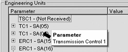
module broadcasts and receives via J1939. Refer to the Allison Transmission DATALINK COMMUNICATIONS technical document, available on the Allison Transmission Extranet, for specific information for each of the displayed J1939 Messages/Parameters. • Parameter—displays SAE J1939 Messages the TCM can receive/send. Each SAE J1939 Message can be expanded to display the corresponding SAE J1939 parameter.
TOOL TIP: Each SAE J1939 Message is displayed in its acronym form. In order to see the complete/long description of a Message, place the cursor (do not click) over its acronym, and a tool tip is displayed.
Since each Message can be broadcasted from different Source Addresses (SA), the tool displays every detected SA that can initiate a given Message. Consequently, if the user is interested in finding a particular J1939 parameter (for example, Percent Load at Current Speed), the first step would be to find out which J1939 Message contains that parameter (EEC2: Electronic Engine Controller # 2), and second to see if Databus Viewer has detected that message in the databus. If detected, the Databus Viewer will display the SA of the controller sending that particular message. At this point, the user can expand that message to display the parameter of interest. • Value—the value/state of the parameter. • Units—the units of measure used for the value.
Source Addresses
Describes all Source Addresses (SA) that can be included/displayed in the Data Bus Viewer.
MID/SA
(J1708 or J1850 only) Message Identifier/Source Addresses code—the message type/source/destination.
Component ID
(J1708 or J1850 only) Manufacturer of a controller.