4 minute read
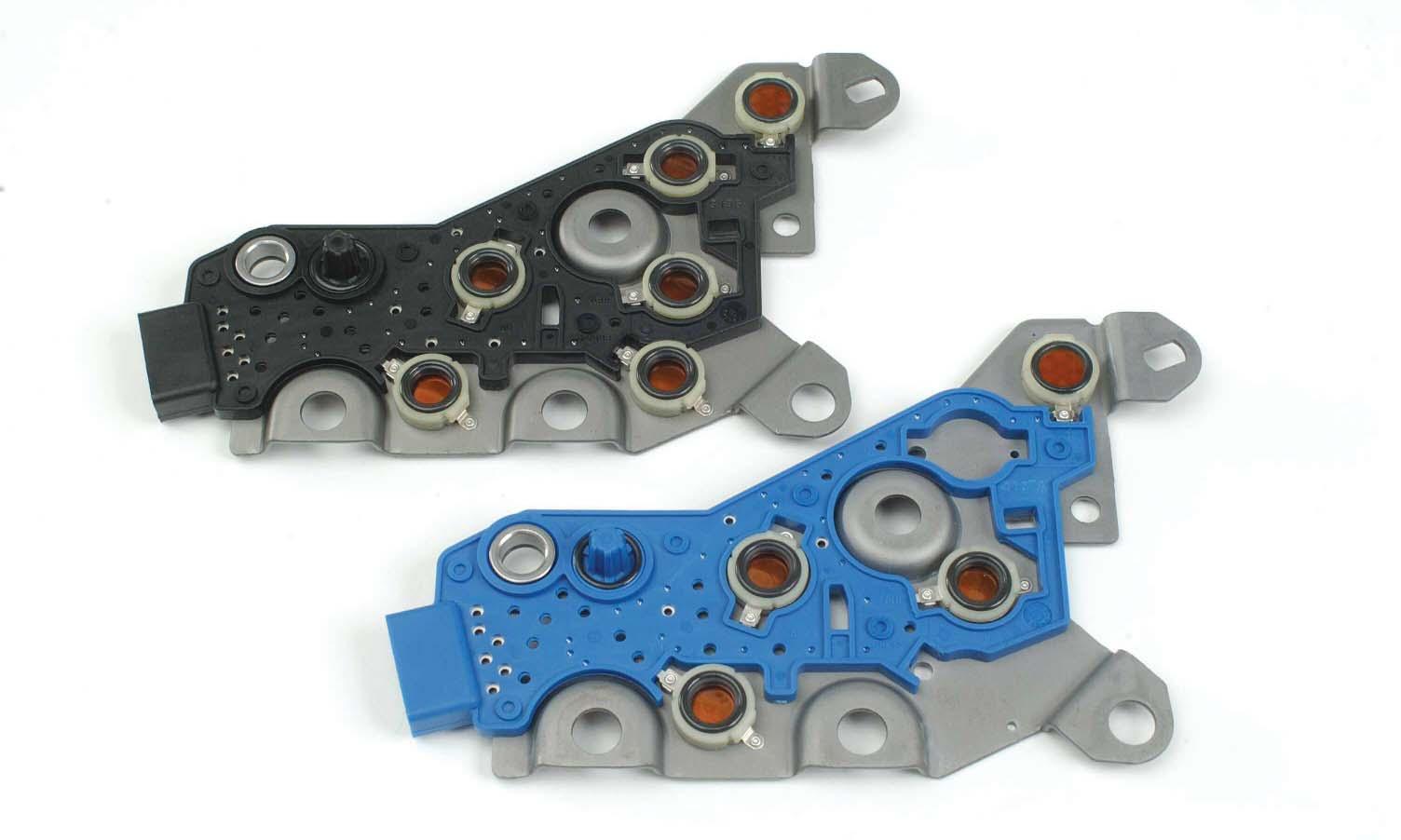
Control Valve Body Assembly


Shift Valve Body Reverse Signal Tube
Identification Detail:Control Valve Body Assembly
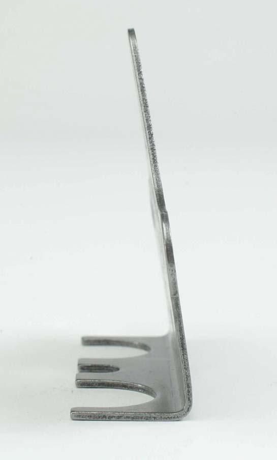
Separator Plate Modulated Main Valve Body
Main Valve Body
Pressure Switch Manifold
General Valve Body Component Inspection Guidelines
Inspect valve bodies. Inspect valve bores and oil passages for nicks, bores, scoring and debris. Replace the valve body if damage cannot be repaired using a soft stone or crocus cloth.
Valves must be free of nicks, burrs and scoring. A soft stone or crocus cloth can be used to attempt removal of slight irregularities. Valves must operate in their bores smoothly without sticking or hanging. (continued)
A Solenoid Pressure Switch Manifold Reverse Signal Tube

G Solenoid
B Solenoid
C Solenoid
D Solenoid E Solenoid F Solenoid (Lockup) Manual Selector Valve
Identification Detail: Main Valve Body Assembly
Exhaust Backfill Valve
E Solenoid
D Solenoid
F Solenoid C Solenoid Retainer
B Solenoid

A/B Retaining Bracket Gain Valve
A Solenoid Accumulators
Trim Valve
E Shift Valve
D Shift Valve
Manual Selector Valve & Pin Control Relief Valve
Identification Detail: Shift Valve Body Assembly
C Shift Valve Control Main Valve
Plug
NOTE: 1000/2000 Product Families valves are anodized aluminum. Do not remove the gray coating from the valve surface.
NOTE: Do not use impact guns (air wrenches, impact wrenches, etc.) when working with aluminum threads or when torque sequencing bolts.
Replace valve springs which are broken, cracked, permanently set or worn due to rubbing adjacent parts. Reference the Spring Data Charts in the Service Manual for spring specifications and identification. Retaining clips and retention pins must be free of nicks, burrs, scoring, battering and other damage. Replace retainers or pins which have damage that cannot be removed using a light stone or crocus cloth.
Replace solenoids if they are visibly damaged or if they have been exposed to anti-freeze and/or water. Check solenoid resistance following Troubleshooting Manual TS3192 guidelines and specifications. Replace the solenoid if resistance is not within Troubleshooting Manual specifications. Inspect the separator plate for scoring, scratches, burrs and nicks. Replace the plate if damage cannot be repaired using a soft stone or crocus cloth, or if the plate is cracked or bent.
(continued)
Identification Detail: Main Valve Body (front) Identification Detail: Main Valve Body (back)

Inspect the internal wiring harness connectors and terminals for visible damage. Inspect the harness protective covering and plastic retainer for cracks, chafing, rubbing and broken pieces. Replace and repair components as necessary. Replace the main connector O-ring if it is cracked, fretted or does not properly fit in its groove or in the main housing. NOTE: Reference the 1000/2000 Product Families Principles of Operation Manual (PO3065) for complete valve body oil passage detail.

(continued)
Identification Detail: Modulated Main Valve Body Detail
Retaining Clip G Solenoid Valve Body
G Solenoid
Pressure Output Supply Port (Control Main)
Valve bores must be free of nicks,burrs and scoring.
B. Valve Bores
A. Valves

Valves should move freeely in their bores,when dry,under their own weight.
A. Valves must be free of nicks, burrs and scoring and operate smoothly in their bores without sticking. Dry valves must move freely in their bores by their own weight. Replace damaged valves. A soft stone or crocus cloth can be used in an attempt to repair slight irregularities. B. Valve bores must be free of nicks, burrs and scoring. No honing of any kind is allowed. A soft stone or crocus cloth can be used in an attempt to repair slight irregularities. NOTE: Use caution not to round land edges on valves or valve bores. Excessive rounding can cause unwanted leakage.
C,D,E and G Solenoids (on/off)
Identification Detail: Solenoids
Supply Port (Control Main)
Pressure Output

A Trim Solenoid (PPC)
Identification Detail: Pressure Switch Manifold
Exhaust Backfill & Thermister D Pressure Switch
C Pressure Switch
Exhaust Backfill & Thermister F Solenoid Lockup (PWM)
Trim Signal
Not Used Pressure Output
Exhaust
B Trim Solenoid (PPC)
Reverse
E Pressure Switch Supply Port
Reference the Troubleshooting Manual for switch testing procedures.
Reverse
D Pressure Switch
E Pressure Switch
C Pressure Switch
Identification Detail: Internal Wiring Harness Assembly
A Solenoid
Pressure Switch Manifold B Solenoid F Solenoid

D Solenoid
E Solenoid G Solenoid
C Solenoid Supersession Information
TCM And Calibration Updates- Reference SILs 2-1K2K-01,4-1K2K-02,3-1K2K-03, 7-1K2K-03,26-1K2K-03
TCM And Calibrations Have Evolved And Continue To Update
Main Connector