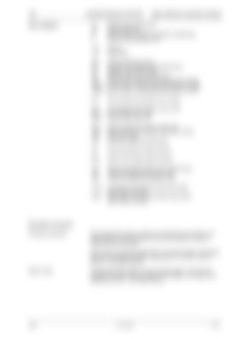
TIC Key to diagram:
LEXION Montana 570-520
Basic Machine Hydraulic System
K-1 K-2 N S
Release parking brake ram Service brake ram Parking brake emergency operation (mechanical) Brake air gap adjusting screw
110 112
Oil tank Return filter
205 211 217 231 313 3003-1 3003-2
Working hydraulics pump Ground drive variable-displacement pump Radiator chaff screen pump Montana axle control system pump Ground drive pump servo control hydraulic cylinder Service brake / Parking brake right hydraulic cylinder Service brake / Parking brake left hydraulic cylinder
516
Service brake accumulator 0.75 l / 80 bar
614 642-1 642-2
Front attachment lower flow control valve Service brake valve, right Service brake valve, left
703 706-5 732 743
Working hydraulics pressure relief valve Rotary chaff screen pressure relief valve 150 bar Non-return valve Lower front attachment pilot spool
901
Working hydraulics measuring point
B90
Brake circuit charge pressure sensor
Y77 Y85 Y87
Working hydraulics master valve solenoid valve Raise front attachment solenoid valve Lower front attachment solenoid valve
Z79-3
Left brake circuit pressure actual value switch (accumulator warning) Right brake circuit pressure actual value switch (accumulator warning)
Z80-3
Description of function: Emergency operation
The parking brake system consists of a spring-type accumulator in the brake cylinders. The low-pressure circuit of the machine is used for releasing the parking brake. If the hydraulic circuit fails (depending on the diesel engine!), the parking brake can be released manually, using screw N. To do this, screw in screw N – see Repair Manual.
Brake air gap
05/06
The Montana brake system is a wet multi-disc brake. To ensure freewheeling of the discs when the brake is not actuated, an air gap can be adjusted at screw S – see Repair Manual.
Lex-h-Kap3
3-157


