2 minute read
Uni-spreader fan drive pump


Key to diagram:
305 AUTOCONTOUR cross levelling right hydraulic cylinder 306 AUTOCONTOUR cross levelling left hydraulic cylinder
406 Orifice plate F..............................................................ÿ 0.8 mm
502 AUTOCONTOUR / Cross levelling accumulator
602 AUTOCONTOUR / Cross levelling shut-off valve 603 AUTOCONTOUR / Cross levelling balance screw
706-3* Cross levelling pressure relief valve (Montana)..........200 bar 706-4* Cross levelling pressure relief valve (Montana)..........200 bar 732 Non-return valve 734 Lock-up valve unit (non-return valve) 740 AUTOCONTOUR cross levelling flow control valve 776 Reversing connecting valve
Y67 AUTOCONTOUR cross levelling left solenoid valve Y68 AUTOCONTOUR cross levelling right solenoid valve Y110 Raise cutting angle solenoid valve Y111 Lower cutting angle solenoid valve Y112 Rotate front attachment to the right solenoid valve Y113 Rotate front attachment to the left solenoid valve
III Autocontour / Reverse valve block
Note: When dismounting items 502, 732, 740, Y67 or Y68, the accumulator must be relieved at the pressure relief bolt (603) before.
3.18
Service brake
3.18.1 Filling the brake accumulator ñ LEXION 600 Terra Trac, LEXION Montana...................3-154
Non-muscular-energy braking system....................................................................................3-154 Brake cylinders.......................................................................................................................3-156
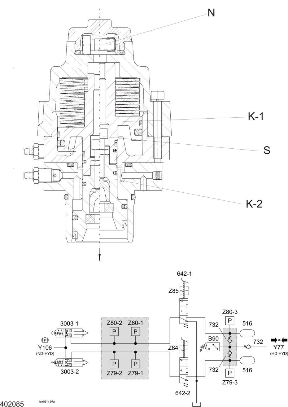
3.18.1 Filling the brake accumulator ñ LEXION 600 Terra Trac, LEXION Montana
Non-muscular-energy braking system
Key to diagram:
110 Oil tank 112 Return filter
205 Working hydraulics pump 211 Ground drive variable-displacement pump 217 Radiator chaff screen pump 231 Montana axle control system pump 313 Ground drive pump servo control hydraulic cylinder 3003-1Service brake / Parking brake right hydraulic cylinder 3003-2Service brake / Parking brake left hydraulic cylinder
516 Service brake accumulator 0.75 l / 80 bar
614 Front attachment lower flow control valve 642-1 Service brake valve, right 642-2 Service brake valve, left
703 Working hydraulics pressure relief valve 706-5 Rotary chaff screen pressure relief valve 150 bar 732 Non-return valve 743 Lower front attachment pilot spool
901 Working hydraulics measuring point
B90 Brake circuit charge pressure sensor
Y77 Working hydraulics master valve solenoid valve Y85 Raise front attachment solenoid valve Y87 Lower front attachment solenoid valve
Z79-3 Left brake circuit pressure actual value switch (accumulator warning) Z80-3 Right brake circuit pressure actual value switch (accumulator warning)
Description of function:
Charging the brake circuit accumulators is part of the working hydraulics. For further information on the brake system see chapter 10.
Brake pressure accumulator The sensor (B90) controls the brake system accumulator pressure and, if necessary, actuates the working hydraulics master valve (Y77) in order to recharge the brake circuit accumulator to 135 ñ 165 bar.
Brake oil pressure warning When the accumulator pressure drops below 115 bar, this is displayed by the brake circuit pressure actual value switches (Z79-3, Z80-3) on terminal (A30) as a warning. In this process, the left brake circuit (Z79-3) and the right brake circuit (Z80-3) are monitored independently of one another.
Service brake Brake cylinders