UENR3677 October 2012
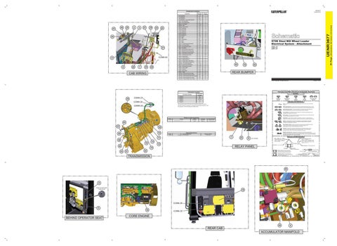
Component Locations
2
3
27
28
23
24
44
21
CONN 63
17
26
9
1
25
29
CAB WIRING
C-12
1
F-6
2
Arc Suppressor
G-6
3
Arc Suppressor - Accumulator Manifold
E-12
4
Base - Fuse (Switched)
I-9
5
Base - Fuse (UnSwitched)
I-8
6
Breaker - Auto-Reset
H-10
7
Breaker - Main
H-10
8
Breaker - Power Switch
H-5
9
Clutch 1 (Reverse)
C-9
10
Clutch 2 (Forward)
C-9
11
Clutch 3 (Speed 4)
B-8
12
Clutch 4 (Speed 3)
B-8
13
Clutch 5 (Speed 2)
A-8
14
Clutch 6 (Speed 1)
C-9 A-11
15
ECM - Engine ECM - SDM
D-7
17
ECM - Transmission
B-1
18
LED - Green
G-12
19
LED - Green
F-6
20
Relay - Forward Solenoid Disconnect
G-1
21
Relay - Low Current Mode
G-10
22
16
Relay - Override Backup Alarm
F-1
23
Relay - Park Brake
E-1
24
Relay - Reverse Solenoid Disconnect
G-1
25
Relay - Solenoid Common Disconnect
G-1
26
Relay - Transmission Override Indicator Relay - Transmission Override Input
F-1 F-1
27
972K Steel Mill Wheel Loader Electrical System - Attachment PEM1-UP Z4W1-UP
28
Relay - 1st Solenoid Disconnect
H-1
29
Sensor - Speed (Input)
C-8
Sensor - Speed (Output 1)
C-8
30 31
Sensor - Speed (Output 2)
C-8
32
Sensor - Position (Steer Valve Spool)
A-7
33
Sensor - Transmission Oil Temperature
C-8
34
Solenoid - Accumulator Manifold
E-12
35
Switch - Custom Ground Shutdown
F-12
42
Switch - Parking Brake Override
G-12
43
Switch - Power Toggle
H-4
44
Switch - Pressure
E-11
45
Switch - Start Toggle
H-4
46
Switch - Toggle
G-5 C-7
47
Valve Gp - Solenoid (Left Prime Steer) Valve Gp - Solenoid (Left Second Steer)
B-7
37
Valve Gp - Solenoid (Prime Steer Pilot Supply)
B-7
38
Valve Gp - Solenoid (Right Prime Steer)
B-7
39
Valve Gp - Solenoid (Right Second Steer)
B-7
40
42
43
19
REAR BUMPER
36
© 2012 Caterpillar, All Rights Reserved
Harness And Wire Electrical Schematic Symbols
Connector Location
34
CONN 24
Symbols
Schematic Location
Connector Number
CONN 23
CONN 23
B-6
CONN 24 CONN 25 CONN 29
B-6 D-3, D-5
CONN 63
E-6
T
Pressure Symbol
Temperature Symbol
Level Symbol
Flow Symbol
Circuit Breaker Symbol
C-5
Symbols and Definitions Fuse: A component in an electrical circuit that will open the circuit if too much current flows through it.
The connectors shown in this chart are for harness to harness connectors. Connectors that join a harness to a component are generally located at or near the component. See the Component Location Chart.
CONN 25
Printed in U.S.A.
Switch (Normally Open): A switch that will close at a specified point (temp, press, etc.). The circle indicates that the component has screw terminals and a wire can be disconnected from it. Switch (Normally Closed): A switch that will open at a specified point (temp, press, etc.). No circle indicates that the wire cannot be disconnected from the component. Ground (Wired): This indicates that the component is connected to a grounded wire. The grounded wire is fastened to the machine. Ground (Case): This indicates that the component does not have a wire connected to ground. It is grounded by being fastened to the machine.
Off-Machine Switch Specification Part No. 174-4312
Function
Actuate 8270 kPa Max
Parking Brake Pressure Switch
1199 psi
40
Deactuate 6890±345 kPa 999±50 psi
Reed Switch: A switch whose contacts are controlled by a magnet. A magnet closes the contacts of a normally open reed switch; it opens the contacts of a normally closed reed switch.
Contact Position A-B Normally open
Sender: A component that is used with a temperature or pressure gauge. The sender measures the temperature or pressure. Its resistance changes to give an indication to the gauge of the temperature or pressure.
A-C Normally closed T
37
Relay (Magnetic Switch): A relay is an electrical component that is activated by electricity. It has a coil that makes an electromagnet when current flows through it. The electromagnet can open or close the switch part of the relay.
30 10
39
Solenoid: A solenoid is an electrical component that is activated by electricity. It has a coil that makes an electromagnet when current flows through it. The electromagnet can open or close a valve or move a piece of metal that can do work.
Component Description
Part No. 152-8340
Solenoid
Accumulator Manifold
Resistance (Ohms)¹ 32.6±1.6 ohms
7
11 38 15 36 33
22
Harness and Wire Symbols
8
NOT SHOWN
13
Wire, Cable, or Harness Assembly Identification: Includes Harness Identification Letters and Harness Connector Serialization Codes (see sample).
Harness Identification Letter(s): (A, B, C, ..., AA, AB, AC, ...)
L-C12 3E-5179
AG-C4 111-7898
12
RELAY PANEL
14 31
Magnetic Latch Solenoid: A magnetic latch solenoid is an electrical component that is activated by electricity and held latched by a permanent magnet. It has two coils (latch and unlatch) that make electromagnet when current flows through them. It also has an internal switch that places the latch coil circuit open at the time the coil latches.
Solenoid Specifications
1
Part Number: for Connector Plug
Part Number: for Connector Receptacle
2 Plug
32
L-C12 3E-5179
Harness Connector Serialization Code: The "C" stands for "Connector" and the number indicates which connector in the harness (C1, C2, C3, ...).
Receptacle Pin or Socket Number
1 2
Deutsch connector: Typical representation of a Deutsch connector. The plug contains all sockets and the receptacle contains all pins.
1 2
Sure-Seal connector: Typical representation of a Sure-Seal connector. The plug and receptacle contain both pins and sockets.
5A Fuse (5 Amps)
9X-1123
Component Part Number
325-AG135 PK-14
TRANSMISSION
Harness identification code: This example indicates wire group 325, wire 135 in harness "AG".
45
5 BACK OF SWITCHED FUSE BLOCK
18
CONN 29 6 16
BEHIND OPERATOR SEAT
CONN 25
CORE ENGINE 35
4
REAR CAB ACCUMULATOR MANIFOLD
Wire Gauge Wire Color
(Dimensions: 48 inches x 35 inches)
47
20
Arc Suppressor Arc Suppressor
36 Page,
46
Machine Location
UENR3677
Schematic Location
Component