44 minute read
Engine


NOTE: Whenever a part is worn excessively,
cracked, or damaged in any way, replacement is necessary.
SPECIAL TOOLS A number of special tools must be available to the technician when performing service procedures in this engine section.
NOTE: When indicated for use, each special tool
will be identified by its specific name, as shown in the chart below, and capitalized.
NOTE: Special tools are available from the Arctic
Cat Service Parts Department.
Description p/n
Drive Clutch Bolt Tool 0644-281 Drive Clutch Puller 0744-062 Drive Clutch Spanner Wrench 0644-136 Engine Lift Plate 0744-073 Hood Harness Extension 1686-659
CAUTION
Never attempt to substitute any other drive clutch puller for the recommended puller or severe clutch or crankshaft damage will occur.
Engine Removing/Installing
This engine sub-section has been organized to show a progression for the removing/installing the Arctic Cat 9000 engine. For consistency purposes, this sub-section shows a complete and thorough progression; however, for efficiency it may be preferable to remove only those components needing to be addressed. Also, some components may vary from model to model. The technician should use discretion and sound judgment.
Removing
NOTE: While removing the engine, note all cable tie
locations.
1.Remove both access panels; then loosen the two quarter-turns securing the hood. Disconnect the hood harness and pull the hood forward and off of the snowmobile. 2.Remove the seat; then remove the gas cap and retaining nut from the neck of the gas tank. Remove the eight screws securing the console. Remove the console.
YM-176A
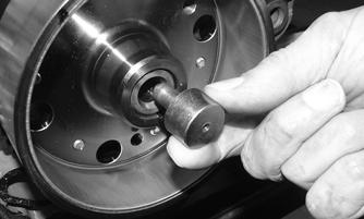
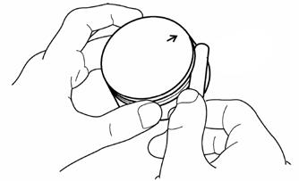
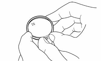
3.Remove the gas tank assembly. 4.Remove the cap screw from the secondary sheave and slide the secondary sheave (along with the drive belt) off the driven shaft. Account for alignment washers and sheave adjuster. 5.Remove the cap screw and washer securing the primary sheave to the crankshaft. 6.Using Primary Sheave Puller, tighten the puller.
Remove the primary sheave. NOTE: If the primary sheave will not release,
sharply strike the head of the puller. Repeat this step until the sheave releases.
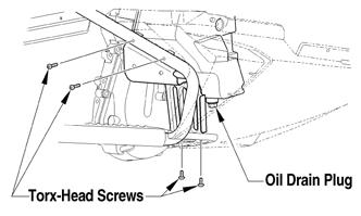
7.Remove the Torx-head screws and both access plates from beneath the snowmobile. 8.Place a drain pan beneath the engine oil drain screw; then remove the screw and allow the oil to drain completely. After the oil has drained, install the drain plug and tighten to 7.2 ft-lb.
YM-152A
9.Remove the four Torx-head screws securing the right-side footrest to the tunnel and the support; then with a drain pan in position, remove the drain plug from the oil tank.
746-121A
NOTE: To aid in draining the oil from the reservoir,
position a funnel between the tank and the opening of the tunnel running board.
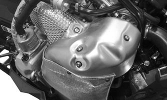
10.After the oil has drained completely, install the drain plug with a new O-ring and tighten to 16 ft-lb. 11. Using a suitable vacuum pump, remove the coolant from the coolant filler neck and the reservoir tank. 12.Remove the five screws and washers securing the turbo heat shield to the turbo. Remove the shield.
YM-181
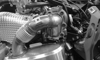
13.Remove the cap screws and washers securing the heat shield to the manifold.
YM-155
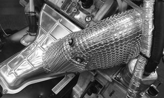
14.Apply a small amount of penetrating lubricant to the threads of the two clamp threads; then remove the two nuts securing the exhaust pipe clamps. Remove the clamps and the pipe.
YM-182A
15.Remove the six Torx screws securing the resonator to the turbo; then remove the spring securing the resonator. Remove the resonator and account for a gasket. NOTE: Apply a small amount of penetrating oil to
the Torx screws before removing the screws. Disassemble with hand tools and T50 ball head Torx bit (p/n 0644-623).
YM-154
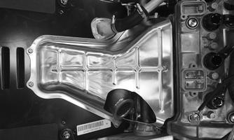
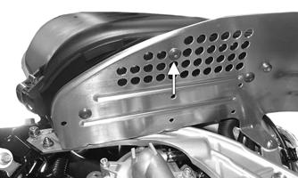
16.Remove the screws and washers securing the exhaust heat shield to the tunnel.
YM-157
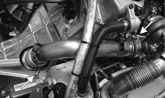
17.Remove the hose clamps securing hoses to the turbo, intake manifold, intercooler, and the air bypass valve. Remove both hoses.
SNO-835A
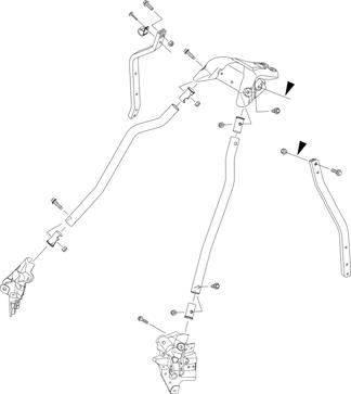
18.Remove the steering post assembly; then remove the two cap screws and nuts securing the vapor tank to the right-side support. 19.Remove the cap screws securing the front spars to the chassis; then remove the cap screws and nuts securing the right-side support to the chassis.
Remove the steering support as an assembly.
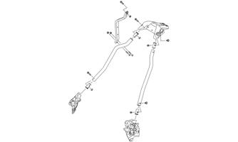
SNO-836
20.Remove the screws securing the air silencer to the clutch guard; then disconnect the hose from the top of the engine and the waste gate hose. Remove the air silencer assembly.
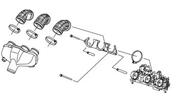
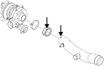
SNO-837
22.Remove the clamp securing the intake duct to the
PTO-side of the turbo. 23.Remove the hose clamp securing the coolant hose to the vapor tank; then remove the hose clamp securing the coolant hose from the bottom of the turbo.
YM-164
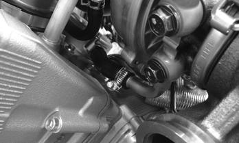
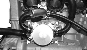
24.Remove the clamp securing the oil return hose to the crankcase; then remove the oil delivery hose to the cylinder. Account for two washers.
YM-185A
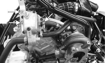
21.Remove the two cap screws and spacers securing the intake manifold and throttle body to the engine; then remove the three clamps securing the intake boots to the throttle body. Remove the intake manifold.
YM-165A
YM-163
25.Remove the four cap screws and four nuts securing the right-side chassis support to the chassis. Remove the turbo and support assembly. 26.Remove the three screws and one nut securing the clutch guard; then remove the screws and nuts securing the left-side chassis support. Rotate the support up to gain access to the rear engine cap screw.
YM-186
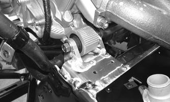
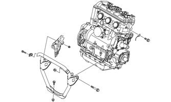
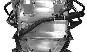
27.Remove all six cap screws and nuts securing the front engine bracket; then remove the bracket.
Remove the cap screw securing the ground wire to the engine.
ONS-030
28.Remove the cap screw and nut securing the rear of the engine to the chassis.
YM-160
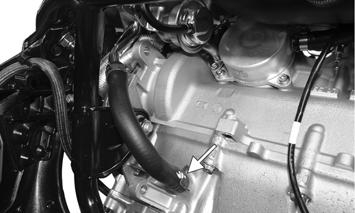
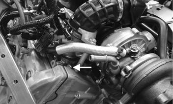
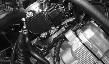
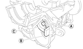
29.Remove the clamp securing the MAG-side coolant hose to the engine; then disconnect the oil pressure switch and the oil pressure sensor. 30.With all hoses and wires disconnected from the engine, move the engine forward and out the right-side of the chassis. 31.Remove the throttle body assembly once the engine is removed.
Installing
NOTE: Before installing the engine, be sure the
starter motor and cables are installed and secured to the engine.
YM-162
NOTE: If the thermostat-to-heat exchanger coolant
hose was removed, make sure it is properly routed and installed onto the heat exchanger. Tighten to 35 in.-lb.
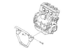
1.Position the front engine bracket with the front engine mounts; then loosely secure using the existing cap screws and new nuts.
SNO-365
2. Carefully lower the engine into the chassis aligning the rear engine mounts with the chassis mounts; then loosely secure using the existing cap screw and a new nut.
ONS-030A
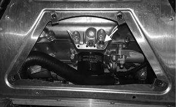
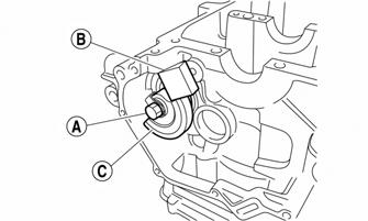
6.Connect the oil pressure switch and the oil pressure sensor to the main harness. 7.Connect the coolant hose from the heat exchanger to the water pump and secure using the existing hose clamp. Tighten to 35 in.-lb. NOTE: All wires, cables, and hoses must be
installed on the inside of the coolant hose and the PTO-side bracket.
CAUTION
Make sure the top clamp is routed like the image below so the clamp does not come in contact with the primary sheave.
YM-160
3.Loosely secure the front engine mounting bracket to the chassis using the existing cap screws and new nuts; then loosely secure the ground cable to the engine using the existing cap screw and a new nut.
ONS-030
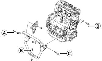
4.Tighten the rear engine cap screw and nut to 65 ft-lb. 5.Tighten the cap screws (A and B) to 25 ft-lb. Tighten cap screw (C) to 65 ft-lb. Tighten cap screw (D) to 96 in.-lb.
YM-161
NOTE: Route the positive and negative battery
cables up and over the engine mounts.
8.Install the throttle body assembly into the three intake boots and secure using the existing clamps.
Tighten to 26 in.-lb.
9.Install the throttle body coolant hoses to the engine and the water pump. Secure using the existing clamps. 10.Install the intake manifold assembly onto the throttle body assembly and secure using the existing clamps.
Tighten to 20 in.-lb. 11.Secure the manifold bracket to the engine using the existing cap screws and spacers. Tighten to 7.2 ft-lb. 15.Secure the oil return hose to the crankcase using the existing clamp; then secure the oil delivery hose to the cylinder using the existing banjo bolt and new washers. Tighten to 7.2 ft-lb.
YM-169
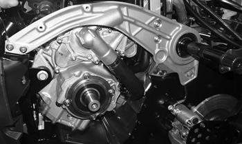
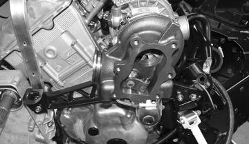
12.Position the right-side rear spar with the chain case assembly; then install the existing cap screws through the chain case and the spar. 13.With the turbo installed onto the MAG-side mounting bracket; secure the assembly to the chassis using the existing screws and nuts. Tighten to 20 ft-lb.
YM-163
14.Connect the lower coolant hose on the backside of the turbo to the oil cooler. Secure using the existing hose clamp. Tighten to 35 in.-lb.
YM-164 YM-165A
YM-163
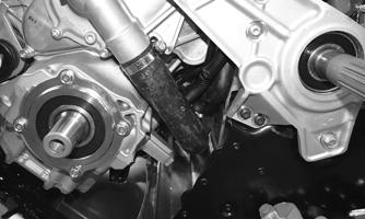
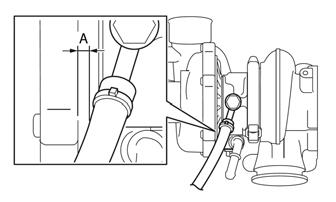
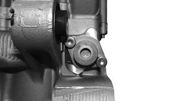
NOTE: Make sure the distance (A) between the oil
delivery hose and the turbo is 3.0 mm (0.12 in.).
SNO-821
16.Install the front two spars to the chassis and loosely secure using the existing cap screws and nuts; then position the steering support over all four spars and loosely secure using the existing cap screws and nuts. Tighten all cap screws to 25 ft-lb.
SNO-828
17.Secure the vapor tank assembly to the right-side rear spar using the existing cap screws and nuts; then connect the coolant hose to the turbo fitting and oil tank breather line to the air intake tube. Tighten the hose clamps to 35 in.-lb. 19.Secure the tie rod assembly to the steering post using a new M10 nut. Be sure to align the tie rod ball joint alignment tab with the steering post. Tighten to 35 ft-lb.
SNO-2219
20.Secure the right-side steering boot to the chassis using the existing push rivets. 21.Secure the top of the steering post to the steering support using the existing retaining plate and nuts making sure the throttle cable is routed between the steering bushings. Tighten to 96 in.-lb. 22.Install the intake duct to the turbo and secure using the existing clamp and boot making sure to align the alignment marks. Tighten the hose clamp to 35 in.-lb.
YM-167A
18.Install steering post through the intake manifold and into position. Secure to the steering stop bracket with a new M10 nut. Be sure to align the steering post
ball joint alignment tab with the steering stop
bracket. Tighten to 43 ft-lb.
SNO-879A
23.Install the air silencer onto the air duct; then install the hoses from the air bypass valve and the hose from the top of the engine into the air silencer.
Secure the silencer using the existing screws.
Tighten securely.
YM-185A
24.Install the intake manifold assembly onto the throttle body and secure using the existing clamps. Tighten to 1.7 ft-lb. 25.Using the long (PTO-side) and the short (MAG-side) spacers, secure the intake manifold assembly to the engine using the existing cap screws. Tighten to 7.2 ft-lb.
SNO-837
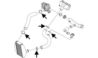
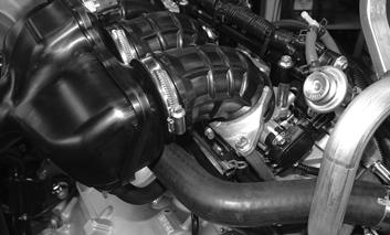
26.Install the hoses to the intercooler, turbo, intake manifold, and air bypass valve using the existing clamps.
Tighten to 35 in.-lb.
SNO-835A
27.Install the exhaust heat shield onto the tunnel and secure using the screws and washers. Tighten securely.
YM-157
28.Position the exhaust gasket between the turbo and the resonator; then using the long T50 ball head Torx bit, secure the resonator to the turbo using the existing screws. Tighten the screws to 9 ft-lb then to 18 ft-lb in a crisscross pattern. NOTE: Apply a small amount of C5-A copper based
anti-seize lubricant to the threads of the screws. Hand tools should be used when installing the six Torx screws.
YM-154
29.Install the exhaust pipe onto the exhaust manifold and the turbo and secure using the existing clamps.
Tighten to 6.1 ft-lb.
YM-182A
30.Install the exhaust heat shield to the exhaust pipe using the existing cap screws and washers. Tighten securely.
YM-155
31.Install the turbo heat shield and secure using the existing cap screws and washers. Tighten securely.
YM-181
32.Install the gas tank assembly and connect the battery; then install the console making sure to connect the reverse alarm and heated seat switch. 33.Install the drive clutch, drive belt, and driven clutch. 34.Install the seat and secure using the screw. On models with a seat heater, connect the seat heater harness connector. 35. Install the hood and both access panels.
Engine Servicing
This engine sub-section has been organized to show a progression for servicing the Arctic Cat 9000 engine. For consistency purposes, this sub-section shows a complete and thorough progression; however, for efficiency it may be preferable to disassemble only those components needing to be addressed. Also, some components may vary from model to model. The technician should use discretion and sound judgment.
SPECIAL TOOLS A number of special tools must be available to the technician when performing service procedures in this engine section.
NOTE: When indicated for use, each special tool
will be identified by its specific name, as shown in the chart below, and capitalized.
NOTE: Special tools are available from the Arctic
Cat Service Parts Department.
Description p/n
Ball Hone 0644-532 Flywheel Puller Kit 0744-083 Piston Pin Puller 0644-328 V Blocks 0644-535 Drive Clutch Spanner Wrench 0644-136 Ring Compressor 0644-378
Disassembling
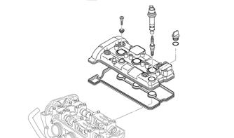
1. With the engine secured to a suitable engine stand, remove the ignition coils from the cylinder head cover; then remove the spark plugs. 2.Remove the four Allen-head screws securing the cylinder head cover to the cylinder head; then remove the cover. Account for the gasket.
SNO-621
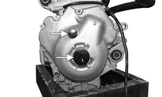
3. Remove both plastic plugs from the MAG cover.
YM-003A
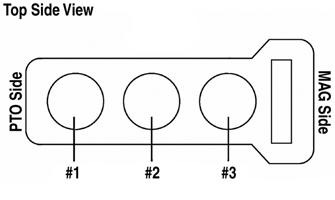
NOTE: The engine cylinders are numbered #1, #2,
and #3 from the PTO to the MAG.
SNO-318A
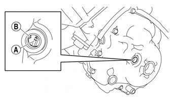
4.Obtain top-dead-center (TDC) by rotating the crankshaft (clockwise) until the mark on the magneto rotor is aligned with the pointer on the magneto cover and the #3 piston is at TDC.
SNO-279A
NOTE: TDC on the compression stroke can be
found when the camshaft lobes for cylinder #3 (MAG side) are turned away from each other.
NOTE: At this point if the technician’s objective is
to service the valves, proceed to Servicing Components - Valves in this sub-section.
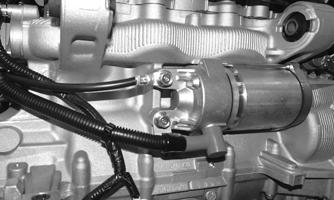
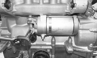
5.Remove the two cap screws securing the starter motor assembly to the crankcase; then remove the starter motor.
YM-080
! WARNING
When removing the cover be sure to keep hands away from being pinched between the cover and the case.
YM-006
6. Remove the Allen-head screws securing the MAG cover to the crankcase taking note the location of
the black screw.
YM-004
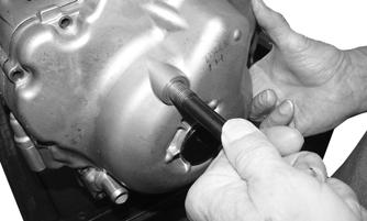
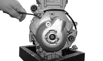
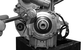
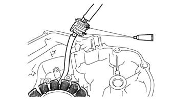
7. Thread the MAG Cover Removal Cap Screw (p/n 2623-100) into the timing mark hole; then carefully pull the MAG cover from the crankcase. Account for two dowel pins and a gasket.
YM-081
8.Remove the starter gear and shaft.
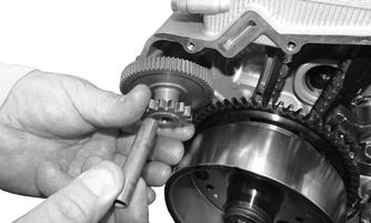
YM-007
9.Remove the cap screw securing the flywheel to the crankshaft. Account for the washer.
10.Using Flywheel Puller, remove the flywheel from the crankshaft. Account for the key in the crankshaft.
YM-082
YM-083
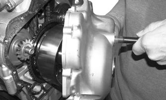
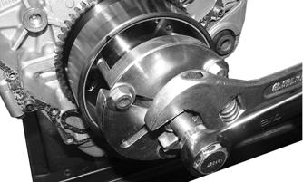
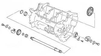
11.Remove the four cap screws securing the output shaft assembly to the crankcase; then thread the drive clutch bolt into the end of the crankshaft and pull the output shaft assembly from the engine.
YM-009
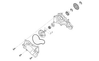
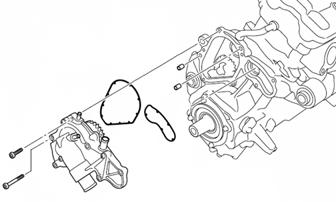
12. Remove the Allen-head screws securing the water pump assembly to the crankcase; then remove the assembly. Account for two dowel pins and two gaskets.
YM-011A
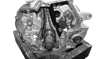
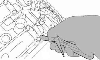
14.Remove the two Allen-head screws securing the chain tensioner to the cylinder assembly. Remove the tensioner and gasket.
YM-012
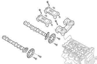
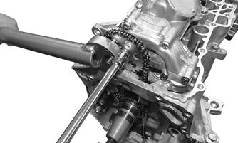
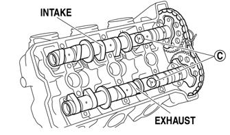
15.Remove the cap screws securing the camshaft covers to the cylinder head; then remove the covers.
Remove both camshafts. Account for the dowel pins that may still be connected to the camshaft caps. NOTE: To prevent damage to the cylinder head,
camshafts, or camshaft caps, loosen the camshaft cap screws in stages and in a criss-cross pattern working from the outside in.
SNO-613
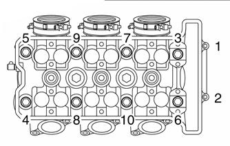
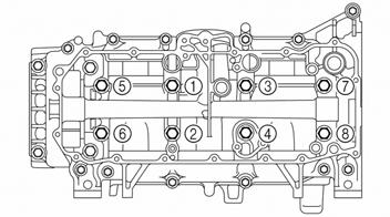
16.Remove the eight cap screws (#3-10) and two
Allen-head screws (#1 and #2). Remove the head and account the gasket and dowel pins.
NOTE: Loosen the cap screws in the proper
sequence as shown. Loosen each cap screw 1/2 of a turn at a time. After all of the cap screws are fully loosened, remove them.
SNO-280
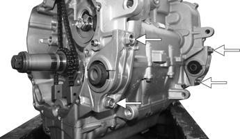
17.Remove the cap screws securing the timing chain tension guides to the engine; then remove the guides.
YM-016A
18.Remove the four cap screws securing the rear engine mounting brackets to the crankcase. Remove the brackets.
YM-017A
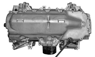
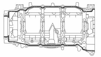
19. Tip the engine upside down; then remove the cap screws securing the oil pan to the crankcase. Using a soft hammer, gently tap around the oil pan until it separates. Account for the oil pan gasket and two dowel pins.
YM-018
NOTE: Note the location of the different-length cap
screws for assembling purposes.
CAUTION
DO NOT drive any tool between the halves to separate the crankcase. Damage to the sealing surfaces will result.
20.Remove the cap screw securing the oil pump driven gear to the oil pump; then remove the oil pump chain and timing chain from the crankshaft.
YM-019
21.Remove the five cap screws securing the oil pump to the crankcase. Account for two dowel pins.
YM-020A
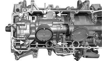
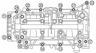
22.Loosen the cap screws in decreasing numerical order of the embossed numbers on the crankcase. Loosen each bolt 1/4 of a turn at a time. After all screws are loosened, remove the screws. Remove the lower case half.
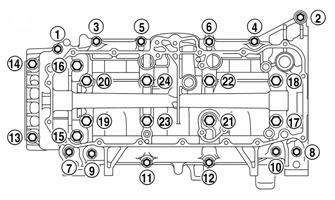
SNO-657A
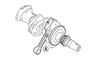
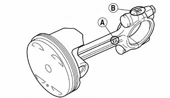
23.Remove the cap screws securing the connecting rod caps to the connecting rods. Account for the bearings.
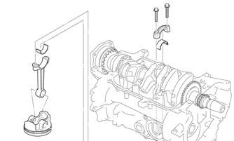
SNO-614
NOTE: The indicator mark (A) on the connecting
rod cap will always point to the MAG end of the crankshaft.
SNO-282A
NOTE: Because the connecting rods and connecting
rod caps are unique, note the I.D. marks and keep all associated parts together for assembling purposes.
24.Remove the crankshaft and piston assemblies from the crankcase.
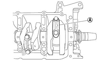
25.Straighten the locking tabs securing the cap screws securing the balancer shaft; then remove both cap screws and both balancer weights.
CAUTION
Pistons can be removed from the top side only.
NOTE: To remove the cap screws (C), place a small
piece of wood (B) between the balancer weight (C) and the crankcase.
SNO-384A
SNO-383A
26.Remove the snap ring securing the water pump drive gear; then remove the gear and shaft and account for a spacer and a bearing.
SNO-319
Servicing Components
Thoroughly clean all non-electrical components in parts-cleaning solvent; then remove any carbon buildup from the cylinder head and piston dome. Visually inspect all engine components for wear or damage.
CAUTION
If any camshaft lobe is discolored or pitted or if the seating surface is worn, the camshaft must be replaced.
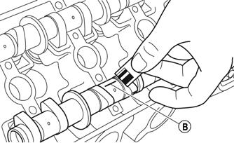
1.Measure the intake camshaft lobe heights (A): 33.750-33.850 mm (1.3287-1.3327-in.). <limit>: 33.650 mm 1.3248-in.
2.Measure the intake base circle diameter (B): 24.950-25.050 mm (0.9823-0.9862-in.). <limit>: 24.850 mm 0.9862-in.
3.Measure the exhaust camshaft lobe heights (A): 33.750-33.850 mm (1.3287-1.3327-in.). <limit>: 33.650 mm 1.3248-in.
4.Measure the exhaust base circle diameter (B): 24.950-25.050 mm (0.9823-0.9862-in.). <limit>: 24.850 mm 0.9783-in.
SNO-721
SNO-722
CHECKING CAMSHAFT RUNOUT
CAUTION
If any camshaft is discolored or pitted or if the seating surface is worn, the camshaft must be replaced.
1.Measure the camshaft runout: 0.030 mm (0.0012-in.). Replace if necessary.
SNO-723
CHECKING CAMSHAFT JOURNAL-TO-CAP Measure the camshaft journal-to-camshaft cap using the following procedure: Clearance — 0.028-0.062 mm (0.0011-0.0024-in.). 1.Install the camshaft into the cylinder heat without the dowel pins and the camshaft caps installed. 2.Position a strip of a piece of Plastigauge® (A) onto the camshaft journal; then install the dowel pins and the camshaft caps.
SNO-724
3.Tighten the camshaft caps cap screws in stages and in a crisscross pattern working from the inner caps outward. Tighten to 7.2 ft-lb. NOTE: Do not turn the camshaft when measuring
the camshaft journal-to-camshaft cap clearance with the Plastigauge®.
4.Remove the camshaft caps and measure the width of the Plastigauge® (B).
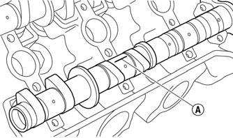
CHECKING CAMSHAFT JOURNAL DIAMETER 1.Measure the camshaft journal diameter (A): 24.459-24.472 mm (0.9630-0.9635-in.). Replace if necessary.
15°-25° C (59°-77° F)
Valve Clearance (Cold)
Intake: 0.0059-0.0087 in. Exhaust: 0.0083-0.0098 in.
SNO-726
2.If the camshaft is within specification, the cylinder heat and camshafts might need to be replaced as a set.
VALVES
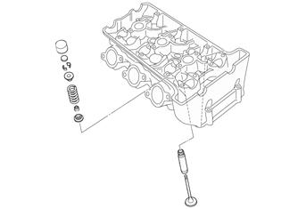
SNO-285
CAUTION
If any valve is discolored or pitted or if the seating surface is worn, the valve must be replaced. Do not attempt to grind a valve or severe engine damage may occur.
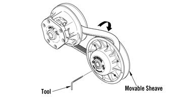
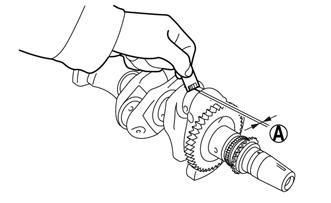
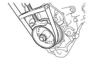
If valves, valve guides, or valve seats require servicing or replacement, Arctic Cat recommends the components be taken to a qualified machine shop for servicing. 1.Install the drive clutch; then using Drive Clutch
Spanner Wrench, rotate the engine two full revolutions.
2.Rotate the engine until the camshaft lobe of the valve being measured is directly away from the tappet. 3.Using an appropriate thickness gauge, measure and record the intake and exhaust valve clearance of the cylinder that is on the compression stroke; then rotate the engine 360° and measure and record the valve clearance of the other cylinder. Valve clearance must be within specifications.
SNO-284
NOTE: At this point if valve/tappet clearances are
within specifications, servicing is complete. If any valve/tappet clearance is not within specifications, complete step 15 of Disassembling before proceeding to step 4.
NOTE: Make a note of the position of each valve
lifter and valve pad so that they can be reinstalled in their original place.
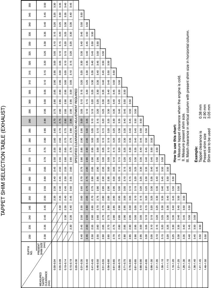
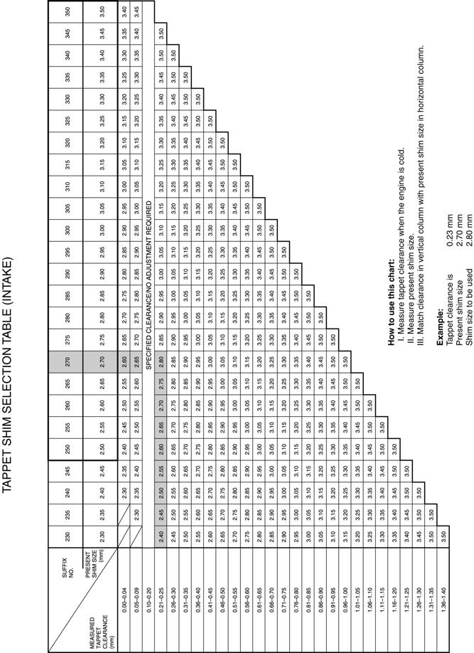
4.To select the correct replacement shim for an out-of-specification clearance, note the three-digit number on the surface of the existing shim; then refer to the appropriate Tappet Shim Selection Table (Exhaust or Intake) in this sub-section and use this procedure:
A.Find the Measured Tappet Clearance (from step 3) in the left-side vertical column of the table.
B.Find the Present Shim Size (three-digit-number) at the top-side horizontal column of the table.
C.Match the clearance in the vertical column with the present shim size to obtain the recommended replacement shim. 5.After verifying proper valve/tappet clearance, install the timing inspection plug to the magneto case and tighten securely. NOTE: At this time, remove the items used to close
off the intake ports of the cylinder head.
CONNECTING ROD BIG END BEARING NOTE: Do not interchange the big end bearings and
connecting rods. To obtain the correct crankshaft-pin-to-big-end-bearing clearance and prevent engine damage, the big end bearings must be installed in their original positions.
1.Clean the big end bearings, crankshaft pins, and bearing portions of the connecting rods.
2.Install the big end upper bearing into the connecting rod and the big end lower bearing into the connecting rod cap. NOTE: Align the projections a on the big end bear-
ings with the notches b in the connecting rod and connecting rod cap.
SNO-298
SNO-617A
NOTE: Do not move the connecting rod or crank-
shaft until the clearance measurement has been completed. Apply molybdenum disulfide oil onto the bolt, threads, and seats.
4.Make sure that the “Y” mark (A) on the connecting rod faces toward the right side (AC magneto rotor side) of the crankshaft.
SNO-618A
5.Make sure that the characters on both the connecting rod and connecting rod cap are aligned.
SNO-619
6.Tighten the connecting rod cap screws; then remove the connecting rod and big end bearings. Measure the compressed Plastigauge® width (A) on the crankshaft pin.
SNO-659
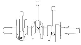
7.Select the big end bearings (P1-P3).
SNO-660
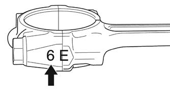
NOTE: The numbers (A) stamped into the crank-
shaft web and the numbers on the connecting rods are used to determine the replacement big end bearing sizes.
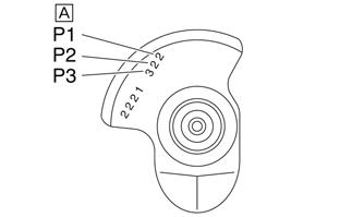
SNO-661
For example, if the connecting rod “P1” and the crank shaft web “P1” numbers are “6” and “2” respectively, then the bearing size for “P1” is: “P1” (connecting rod) –“P1” (crankshaft web) – 1 = 6 – 2 – 1 = 3 (brown).
BIG END BEARING COLOR CODE
0 White 1 Blue 2 Black 3 Brown 4 Green 5 Yellow
CRANKSHAFT JOURNAL BEARING NOTE: Do not interchange the crankshaft journal
bearings. To obtain the correct crankshaft-journal-tocrankshaft-journal-bearing clearance and prevent engine damage, the crankshaft journal bearings must be installed in their original positions.
1.Clean the crankshaft journal bearings, crankshaft journals, and bearing portions of the crankcase. Place the upper crankcase upside down on a bench. 2.Install the journal bearings into the upper engine case.
NOTE: Make sure the tabs of the bearings are prop-
erly seated to the notches in the upper engine case.
SNO-298
3.Put a piece of Plastigauge® on each crankshaft journal.
SNO-320A
NOTE: Do not put the Plastigauge® over the oil
hole in the crankshaft journal.
4.Install the crankshaft journal lower bearings into the lower crankcase and assemble the crankcase halves.
NOTE: Do not move the crankshaft until the clear-
ance measurement has been completed.
5.Tighten the cap screws in the order of the embossed numbers on the crankcase; then remove the lower crankcase and the crankshaft journal lower bearings. 6.Measure the compressed Plastigauge® width on each crankshaft journal.
SNO-320A
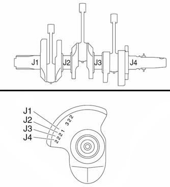
7.If the clearance is out of specification, select replacement crankshaft journal bearings. NOTE: The numbers stamped into the crankshaft
web and the numbers stamped into the lower crankcase are used to determine the replacement crankshaft journal bearing sizes.
SNO-322
NOTE: “J1 - J4” refer to the bearings shown in the
crankshaft web and lower crankcase illustration. If “J1 - J4” are the same, use the same size for all of the bearings.
For example: if the crankcase “J1” and crankshaft web “J1” numbers are “6” and “1” respectively, the bearing size for “J1” is: J1 (crankcase) – J1 (crankshaft web) + 2 = 6 – 1 + 2 = 7.
CRANKSHAFT JOURNAL BEARING COLOR CODE
1 Black 2 Brown 3 Green 4 Yellow 5 Pink 6 Red 7 White
SNO-616
NOTE: Whenever a piston, rings, or pins are out of
tolerance, they must be replaced.
Cleaning/Inspecting Piston 1.Using a non-metallic carbon removal tool, remove any carbon buildup from the dome of the piston. 2.Inspect the piston for cracks in the piston pin, dome, and skirt areas.
3.Inspect the piston for seizure marks or scuffing. NOTE: If seizure marks or scuffing is detected, the
piston must be replaced.
4.Inspect the perimeter of each piston for signs of excessive “blowby.” Excessive “blowby” indicates worn piston rings or an out-of-round cylinder.
Removing Piston Rings 1.Starting with the top ring, slide one end of the ring out of the ring groove. 2.Remove each ring by working it toward the dome of the piston while rotating it out of the groove.
SNO-287
NOTE: If the existing rings will not be replaced with
new ones, note the location of each ring for proper installation. When installing new rings, install as a complete set only.
Measuring Piston-Ring End Gap (Installed) 1.Place each piston ring in the wear portion of the cylinder. Use the piston to position each ring squarely in the cylinder. NOTE: Remove any carbon; then clean the top of
the cylinder bore before inserting the piston rings.
2.Using a feeler gauge, measure each piston-ring end gap. Acceptable ring end gap must be within the following specifications.
1st Ring 0.035-0.045 in. 2nd Ring 0.070-0.080 in. Oil Rings 0.10-0.35 in.
1st Ring 0.030-0.065 in. 2nd Ring 0.02-0.055 in.
Cylinder Bore (C) 3.2283-3.2287 in. Taper Limit (T) 0.0020 in. Out of Round (R) 0.0020 in.
Piston Ring/Groove Clearance NOTE: Before checking, piston grooves must be
clean, dry, and free of carbon.
Fit new piston ring into piston groove and measure clearance between ring and ringland by using feeler gauge. Measurement must be within the following specifications. If clearance is out of specification, replace piston.
SNO-288
Measuring Piston Skirt/Cylinder Clearance 1.Measure the cylinder bore using a gauge by taking side-to-side and front-to-back measurements of the cylinder. Then, find the average of the measurements.
SNO-289
SNO-290
“C” = maximum of D1 - D6 “T” = maximum of D1 or D2 – maximum of D5 or D6 “R” = maximum of D1 D3 or D5 – maximum of D2, D4, or D6
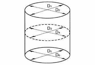
NOTE: If out of specification, replace the crankcase
and the piston and piston rings as a set.
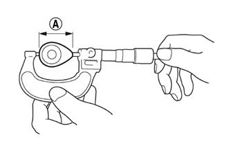
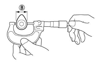
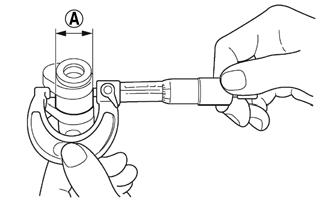
Measuring Piston Skirt Diameter 1.Measure the piston skirt diameter (A) with a micrometer. Be sure to measure 8.0 mm (0.31 in.) from the bottom edge of the piston (B). 2.Piston skirt diameter must be within 81.950-81.965 mm (3.2264-3.2270 in.).
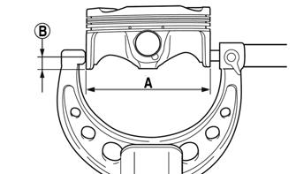
SNO-658A
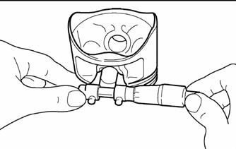
Measuring Piston Pin Bore Diameter NOTE: It may be necessary to use Piston Pin Puller
to remove the piston pins.
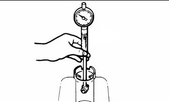
1.Insert an inside dial indicator into the piston-pin bore. Take two measurements to ensure accuracy. 2.Piston pin bore must be within 0.7482-0.7486 in.
SNO-291
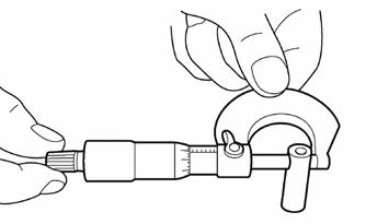
Measuring Piston Pin Diameter Measure the piston pin diameter at each end and in the center. Measurement must be within 0.7477-0.7480 in. If measurement is not within specifications, the piston pin must be replaced.
SNO-292
Installing Piston Rings 1.Install the piston rings according to the illustration below. Stagger the end gaps of the upper and lower thin oil rings until they are on directly opposite sides of the piston.
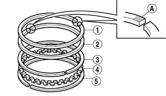
SNO-293A
NOTE: Be sure to install the piston rings so that the
manufacturer marks (A) face up.
2.Rotate the rings until the ring end gaps are 120° from one another.
SNO-294A
CAUTION
Incorrect installation of the piston rings will result in engine damage.
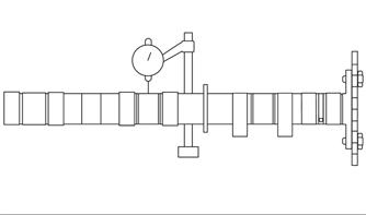
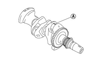
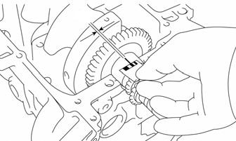
CRANKSHAFT RUNOUT 1.Support the crankshaft using a set of V Blocks; use a dial indicator to read crankshaft runout.
NOTE: The contact point of the dial indicator
should be on either side of the oil port hole of the center crankshaft journal and to the outside of the oil port hole on the MAG and PTO end of the crankshaft.
2.Rotate the crankshaft slowly. 3.The reading must be 0.0012 in. or crankshaft repairing/replacing will be necessary.
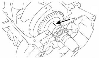
MEASURING CRANKSHAFT MAIN/ROD JOURNALS (Bearing Surfaces) 1.Using a micrometer, measure each main and connecting rod bearing journal from along its length and 90° from the first measurement. Measurement must be within 0.0011-0.0018 in.
2.If any journal is badly damaged or has wear that is not within specifications, the crankshaft must be replaced.
Assembling
NOTE: Arctic Cat recommends new gaskets, seals,
and O-rings be installed whenever assembling the engine.
NOTE: For assembling purposes, use oil-dissolvable
molybdenum disulfide grease as engine-assembly grease.
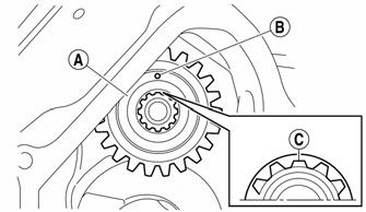
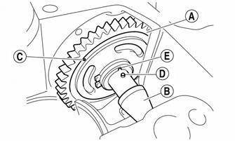
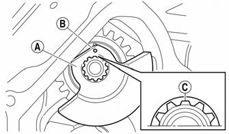
1.Install the balancer driven gear (A); then install the balancer shaft (B) making sure to face the punch mark (C) on the balancer driven gear inward. Align the projection (D) on the balancer shaft with the slot (E) in the balancer driven shaft.
SNO-385A
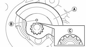
2.Install the water pump drive gear (A) by aligning the punch mark (B) on the water pump gear with the shorter spline (C) on the balancer shaft end.
SNO-386A
3.Install the right balancer weight (A) onto the shaft; then install the washers, lock washers, and secure using the existing cap screws making sure to align the punch mark (B) on the shaft with the shorter spline (C) on the shaft end.
SNO-387A
4.Install the left balancer weight (A) onto the shaft; then install the washers, lock washers, and secure using the existing cap screws making sure to align the punch mark (B) on the shaft with the shorter spline (C) on the shaft end.
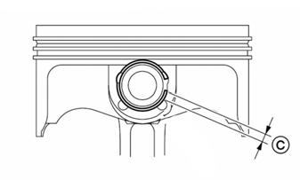
7.Install the piston pin clips so the clip ends are 3 mm (0.12 in) (C) or more from the cutout in the piston.
Make sure the oil ring end gaps are on directly opposite sides of the piston and the compression ring end gaps are 90° from one another.
SNO-388A
5.Secure the balancer weights (C) using a small piece of wood (B). Tighten cap screws to 25 ft-lb; then bend the locking washer over the cap screw (A).
SNO-384A
SNO-383A
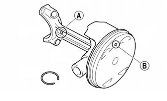
6. Apply engine oil onto the piston pin. Make sure the
“Y” mark (A) on the connecting rod faces to the
MAG side when the punch mark (B) on the piston is pointing up.
SNO-296
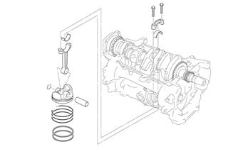
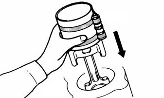
8.With the piston rings installed, lubricate each piston and cylinder with engine oil; then with the punch marks on the top of the pistons directed toward the exhaust side of the engine, install the piston assemblies into the cylinder using Ring Compressor and a soft hammer.
SNO-297
9.Rotate the engine to the upside down position for installing the crankshaft. 10.With the proper bearings selected, install the half-bearings into the upper engine case; then lubricate the bearing faces liberally with engine-assembling grease taking care not to get any grease between the engine case and bearing. NOTE: Make sure the tabs of the bearings are prop-
erly seated to the notches in the upper engine case.
11.Lubricate the lips of the crankshaft seal with grease and install the crankshaft seal over the PTO end of the crankshaft with the spring side of the seal directed toward the crankshaft; then install the crankshaft.
NOTE: Make sure the “Y” marks (A) on the con-
necting rods face toward the right side (MAG side) of the crankshaft. Make sure the characters (B) on both the connecting rod and connecting rod cap are aligned.
SNO-299A
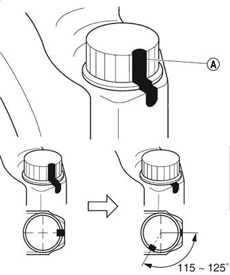
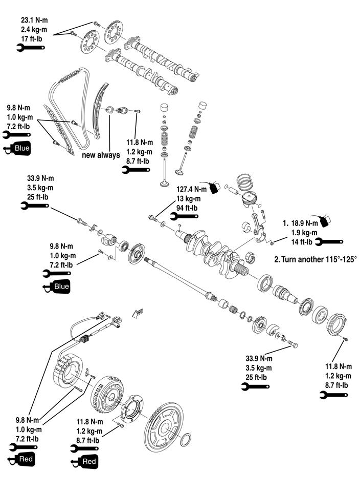
12.Seat the connecting rods to the crankshaft; then install the connecting rod caps, new cap screws, and new nuts. Tighten only until snug at this time. 13.Alternately, tighten each of the connecting rod cap screws evenly to 14 ft-lb; then put a mark (A) on the corner of the connecting rod cap screw. Tighten the connecting rod cap screw further to reach the specified angle (115-125°). 14.Using Three Bond Sealant, apply a light film of sealant onto the sealing surfaces of the upper and lower engine cases.
SNO-301
NOTE: Do not allow any sealant to come into con-
tact with the oil galley or crankshaft journal bearings. Do not apply sealant to within 0.08-0.12 in. of the crankshaft journal bearings.
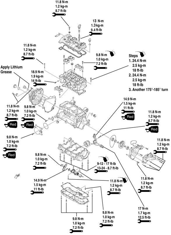
15.Install the lower crankcase half to the upper engine case; then verify the cases are properly seated together. 16.Install the cap screws into the proper locations in the crankcase; then with the torque pattern shown as numbered on the case, tighten the cap screws only until snug.
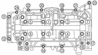
SNO-302
NOTE: Lubricate cap screws 1-8 threads and wash-
ers with engine oil. Lubricate bolts 9-15 and 19-24 threads and mating surface with engine oil. Apply Three Bond Sealant to the threads of cap screws 16-18.
17.Tighten crankcase cap screws 1-8 to 11 ft-lb; then loosen and re-tighten to 11 ft-lb. 18.Tighten the cap screws 1-4 an additional 95°-100°; then tighten cap screws 5-8 an additional 75°-80°.
SNO-620A
NOTE: Rotate the crankshaft one revolution to ver-
ify free movement.
SNO-303
NOTE: If a cap screw is tightened more than the
specified angle, do not loosen the bolt and then re-tighten it. Instead, replace the bolt with a new one and perform the procedure again.
NOTE: Do not use a torque wrench to tighten the
bolt to the specified angle.
19.Tighten cap screws 9-24 in order of the embossed numbers on the crankcase. Tighten cap screws 9-12 to 17 ft-lb and cap screws 13-24 to 8.7 ft-lb.
SNO-304
NOTE: After the tightening sequence, rotate the
crankshaft one revolution to verify free movement.
20.Place the dowel pins in place; then position the oil pump assembly on the crankcase and secure using the existing cap screws. Tighten to 8.7 ft-lb.
YM-020A
NOTE: At this time, install the timing chain around
the crankshaft as it must go on before the oil pump chain.
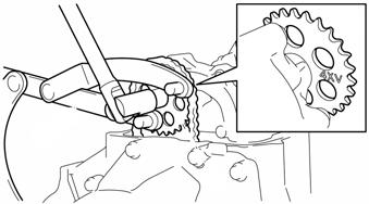
21.Position the oil pump chain around the crankshaft; then install the oil pump driven gear and secure using the existing cap screw. Tighten to 11ft-lb. 22.Position the oil pump chain guide and secure using the existing cap screws. Tighten to 7.2 ft-lb.
YM-019
NOTE: Install the oil pump driven gear with the
stamped mark “4XV” facing toward the oil pump assembly.
SNO-305
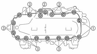
23.With a new gasket and the existing dowel pins in place, install the oil pan and install the different-length cap screws. Using the pattern shown, tighten the screws to 86 in.-lb.
SNO-306
NOTE: If the oil pan drain plug was removed,
always install new drain plug and reservoir washers.
NOTE: At this time, rotate the engine to the upright
position.
24.Secure the rear mounting brackets to the engine case making sure the numbers on the brackets match the numbers on the case. Tighten to 18 ft-lb.
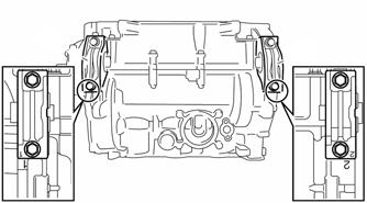
SNO-307
NOTE: Prior to installing the cam chain tensioner,
ensure the chain is properly seated to the gear on the crankshaft.
25.Install the chain guides and secure using the existing cap screws. Tighten to 86 in.-lb.
SNO-625
29.Install the magneto cover and secure using the existing Allen-head screws. Tighten to 8.7 ft-lb. NOTE: Apply blue Loctite #243 to the black
Allen-head screw which should be installed next to the triangle mark on the cover. Tighten to 8.7 ft-lb.
30.Position a new cylinder head gasket onto the crankcase; then position the existing dowel pins into the crankcase.
31.Route the timing chain through the cylinder head assembly and place the head onto the crankcase. NOTE: Make sure to use new cap screws #3-10
when installing the head.
32.Lubricate the new cap screws #3-10; then secure the cylinder head assembly to the crankcase using the existing cap screws. Tighten to 18 ft-lb; then loosen the cap screws and re-tighten to 18 ft-lb.
YM-016A
NOTE: Clean the tapered portion of the crankshaft
and the flywheel.
26.With the key installed into the crankshaft, install the flywheel onto the crankshaft aligning with the key on the crankshaft until it is fully seated. 27.Lubricate the flywheel cap screw and washer with engine oil; then while holding the flywheel with the sheave holder, tighten the cap screw to 130 N-m (13 kg-m, 94 ft-lb).
SNO-624
28.Apply Three Bond Sealant to the stator grommet; then place the grommet into the crankcase groove.
SNO-280
33.Tighten the cylinder head bolts further to reach the specified angle 175°-185° in the proper tightening sequence as shown. Do not use a torque wrench for this step.
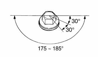
SNO-308
34.Tighten the Allen-head screws #1 and #2 to 104 in.-lb.
35.Position the intake and exhaust camshaft assemblies into the head.
36.Turn the crankshaft clockwise. When piston #3 is at
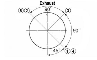
TDC on the compression stroke, align the “I” mark (A) on the magneto rotor with the stationary pointer (B) on the magneto cover. Install the timing chain onto both camshaft sprockets.
SNO-279A
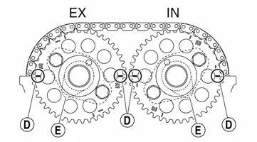
37.Install the camshafts with the hole (C) in cylinder #3 (cam facing up). When installing the timing chain, start with the intake camshaft and be sure to keep the timing chain as tight as possible on the intake side.
Make sure the marks (D) on the timing chain sprockets are parallel with the edge of the cylinder head.
Location (E) is cylinder #3 cam location.
SNO-622A SNO-311A
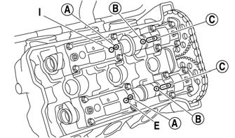
38.Install the existing dowel pins into the cylinder head; then install the intake and exhaust camshaft caps.
Tighten the camshaft cap screws to 86 in.-lb in two stages and in a crisscross pattern working from the inner caps out. NOTE: The “I” mark refers to the intake camshaft
caps and the “E” mark refers to the exhaust camshaft caps. Install the camshaft caps with the arrow mark a pointing toward the MAG side of the engine. Make sure the holes (B) in the camshaft are aligned with the marks (C) on the camshaft caps.
SNO-623A
CAUTION
Lubricate the camshaft cap screws with engine oil. The camshaft cap screws must be tightened evenly or damage to the cylinder head, camshaft caps, and camshafts will result. Do not turn the crankshaft when installing the camshaft to avoid damage or improper valve timing.
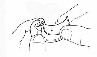
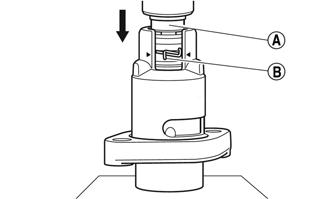
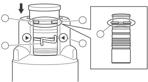
39.Slowly insert the timing chain tensioner rod (A) into the timing chain tensioner housing while squeezing the timing chain tensioner clip (B) until the clip is in the groove.
SNO-626A
40.Insert the timing chain tensioner rod little by little so that the circlip (A) is seated into the groove (B).
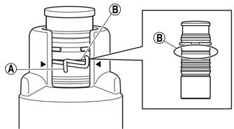
SNO-627A
NOTE: Insert the timing chain tensioner rod little
by little so that the circlip (A) comes into the groove in the rod (B). Check that the mark (C) on the timing chain tensioner housing is aligned with the timing chain tensioner clip (D) and that the timing chain tensioner rod is locked in position.
A
D B
C B
SNO-628A
41.Install the chain tensioner assembly and secure using the existing Allen-head screws. Tighten to 104 in.-lb. NOTE: Be sure to install the timing chain tensioner
gasket so its section with the “L” mark is protruding from the lower left side of the timing chain tensioner. The arrow mark (A) on the timing chain tensioner should face up.
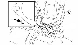
SNO-315A
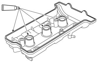
42.Apply Three Bond Sealant onto the mating surfaces of the cylinder head cover and cylinder head cover gasket.
SNO-629
43.Apply Three Bond Sealant onto the mating surfaces of the cylinder head cover gasket (A). After the gasket is installed, cut off the sections (B). Tighten the cylinder head cover screws in a crisscross pattern to 7.2 ft-lb.
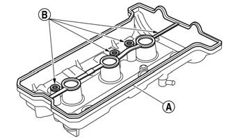
SNO-630A
44.Install the spark plugs. Tighten to 8.7 ft-lb. 45.Install the ignition coils over the spark plugs making sure they are fully seated and aligned with the marks on the cylinder head.
Assembly Schematic
Torque Specification Tolerances Torque (ft-lb) Tolerance
0-15 ±20% 16-39 ±15% 40+ ±10%
Troubleshooting Engine
Problem: Engine Does Not Start (No Spark at Spark Plugs) Condition Remedy
1. Ground connections dirty — loose 1.Check all ground connections — clean and tight 2. Wiring harness shorting — disconnected 2.Repair — replace — connect wiring harness 3. Emergency stop switch in DOWN position — malfunction- 3.Move switch to UP position — replace throttle control ing 4. Throttle/ignition monitor switch malfunctioning 4.Adjust throttle cable tension — replace throttle body assembly 5. Spark plugs fouled — damaged 5.Clean — replace spark plugs 6. Idle speed control (ISC valve) not functioning 6.Turn ignition switch ON and OFF — listen for stepping motor (ISC valve) operation 7. ECM faulty 7.Replace ECM 8. Ignition timing sensor/Crank position sensor faulty 8.Replace sensor
Problem: Engine Does Not Start (No Fuel at Cylinders) Condition Remedy
1. Gas tank empty 1.Fill tank 2. Gasoline contaminated 2.Replace gasoline 3. Fuel pump faulty 3.Service — replace fuel pump — connections — wires 4. Fuel hose broken — pinched 4.Replace — service hose 5. Gas-tank vent — hose obstructed 5.Remove obstruction — replace vent — hose 6. Pick-up valve(s) obstructed — damaged 6.Remove obstruction — replace pick-up valve(s) 7. Compression absent 7.Repair — replace damaged — worn engine components 8. ECM faulty 8.Replace ECM
Problem: Engine Does Not Start (Fuel Does Not Ignite) Condition Remedy
1. ECM Check Engine light failed 1.Check codes — repair as necessary 2. Spark absent 2.Check for spark — see No Spark at Spark Plugs sub-section 3. Compression low 3.Service engine 4. Engine flooded 4.Clear engine (hold throttle full-open) 5. Gasoline contaminated 5.Clean tank and entire fuel system
Problem: Engine Does Not Idle Condition Remedy
1. ECM trouble code 1.Service — replace problem component 2. Throttle cable too tight 2.Adjust throttle cable to specifications* 3. Injector(s) faulty 3.Replace injector(s) 4. Fuel pressure regulator faulty 4.Replace regulator — hose 5. Air silencer obstructed 5.Clean air silencer 6. ISC valve faulty 6.Replace valve
Problem: Engine Loses Power Condition Remedy
1. Sensor faulty 1.Check engine light for trouble code — repair — replace problem circuit or sensor 2. Spark plug fouled 2.Replace spark plugs 3. External coil faulty 3.Service — replace coil 4. Gas tank vent — hose obstructed 4.Service — replace vent hose 5. Compression low 5.Service engine 6. ECM faulty 6.Replace ECM 7. Fuel pressure regulator faulty 7.Replace regulator 8. Check Engine light illuminated 8.Check codes — repair as necessary 9. Injector faulty 9.Replace injector
Problem: Engine Overheats Condition Remedy
1. Coolant low — absent 1.Add coolant 2. Heat exchanger obstructed 2.Remove obstruction 3. Drive system (drive clutch — driven clutch — track — 3.Troubleshoot — adjust drive system drive belt) adjusted incorrectly — worn — damaged 4. Rings/grooves carboned 4.Clean — replace rings — pistons 5. Exhaust obstructed 5.Remove obstruction 6. Compression low — absent 6.Repair — replace damaged — worn engine components 7. Water pump — thermostat damaged — faulty 7.Replace water pump — thermostat
Problem: Engine Backfires Condition Remedy
1. Check Engine light illuminated 1.Check codes — replace problem component 2. Spark plugs fouled — damaged 2.Clean — replace spark plugs
Problem: Engine Stops Suddenly Condition Remedy
1. Gas tank empty 1.Fill tank 2. Spark absent 2.See No Spark at Spark Plugs sub-section 3. Check Engine light illuminated 3.Check codes — replace problem component 4. Fuel filter(s) obstructed 4.Replace filter(s) 5. Fuel pressure low 5.Replace regulator — hose 6. Fuel pump faulty 6.Service — replace fuel pump 7. Fuel pump relay faulty 7.Replace relay 8. Gas tank vent hose obstructed 8.Service vent hose 9. ECM faulty 9.Replace ECM 10. Fuel hose obstructed — broken — pinched 10.Remove obstruction — repair — replace fuel hose 11. Ignition coil faulty 11.Replace ignition coil 12. Engine seized 12.Overhaul engine 13. Throttle/ignition monitor switch — throttle cable tension 13.Replace throttle control — adjust throttle cable faulty — adjusted incorrectly 14. Oil pressure low 14.Check oil level/engine 15. Engine coolant temperature above normal 15.Inspect cooling system