19 minute read
General Information/Foreword


NOTE: General specifications for each 2020 Arctic
Cat Snowmobile can be accessed from the Arctic Cat Cat Tracker Dealer Communication System.
NOTE: Some illustrations and photographs used in
this manual are used for clarity purposes only and are not designed to depict actual conditions.
This Service Manual contains service and maintenance information for 2020 Arctic Cat ZR 9000 Thundercat snowmobile models. The manual is designed to aid service personnel in service-oriented applications. This manual is divided into sections that cover specific snowmobile components or systems and, in addition to the standard service procedures, include assembling, disassembling, and inspecting instructions. When using this manual as a guide, the technician should use discretion as to how much disassembly is needed to correct any given condition. The service technician should become familiar with the operation and construction of the components or systems by carefully studying the complete manual. This will assist the service technician in becoming more aware of and efficient with servicing procedures. Such efficiency not only helps build consumer confidence but also saves time and labor. All Arctic Cat publications and snowmobile decals display the words Warning, Caution, and Note to emphasize important information. The symbol ! WARNING identifies personal safety-related information. Be sure to follow the directive because it deals with the possibility of severe personal injury or even death. A CAUTION identifies unsafe practices which may result in snowmobile-related damage. Follow the directive because it deals with the possibility of damaging part or parts of the snowmobile. The symbol NOTE: identifies supplementary information worthy of particular attention. At the time of publication, all information, photographs, and illustrations were technically correct. Some photographs and illustrations used in this manual are used for clarity purposes only and are not designed to depict actual conditions. Because Arctic Cat Inc. constantly refines and improves its products, no retroactive obligation is incurred. All materials and specifications are subject to change without notice. Product Service and Warranty Department Arctic Cat Inc. The Arctic Cat Snowmobile has two important identification numbers. The Vehicle Identification Number (VIN) is stamped into the tunnel near the right-side footrest or on top of the tunnel. The decal also displays pertinent production information. The Engine Serial Number (ESN) is stamped into the crankcase of the engine. These numbers are required to complete warranty claims properly. No warranty will be allowed by Arctic Cat if the engine serial number or VIN is removed or mutilated in any way.
Recommended Gasoline and Oil
CAUTION
Do not use white gas or gasoline containing methanol. Only Arctic Cat-approved gasoline additives should be used.
RECOMMENDED GASOLINE The recommended gasoline to use in these snowmobiles is 87 octane regular unleaded. In many areas, oxygenates are added to the gasoline. Oxygenated gasolines containing up to 10% ethanol are acceptable gasolines. When using ethanol-blended gasoline, adding a gasoline antifreeze is not necessary since ethanol will prevent the accumulation of moisture in the fuel system.
RECOMMENDED OIL
CAUTION
Any oil used in place of the recommended oil may cause serious damage.
The recommended oil to use is Synthetic C-TEC4 Oil (p/n 6639-529 — gal.). After the engine break-in period, the engine oil and filter should be changed every 2500 miles or before prolonged storage.
Engine Break-In
The engine (when new or rebuilt) requires a short break-in period before the engine is subjected to heavy load conditions.
This engine does not require any pre-mixed fuel during the break-in period. There is never a more important period in the life of the engine than the first 500 km (300 miles). Since the engine is brand new, do not put an excessive load on it for the first 500 km (300 miles). The various parts in the engine wear and polish themselves to the correct operating clearances. During this period, prolonged full throttle operation or any condition that might result in engine overheating must be avoided.
Operating your snowmobile for the first time: Start the engine and let it idle for 15 minutes. 0-160 km (0–100 miles): Avoid prolonged operation above 6000 RPM.
160-500 km (100–300 miles): Avoid prolonged operation above 8000 RPM.
500 km (300 miles) and beyond: The snowmobile can now be operated normally. NOTE: After 800 km (500 miles) of operation, the
engine oil must be changed and the oil filter replaced. If any engine trouble should occur during the engine break-in period, immediately have an Arctic Cat dealer check the snowmobile.
Drive Belt Break-In
Drive belts require a break-in period of 25 miles. Drive the snowmobile for 25 miles at 3/4 throttle or less. By revving the engine up and down (but not exceeding 60 mph), the exposed cord on the side of a new belt will be worn down. This will allow the drive belt to gain its optimum flexibility and will extend drive belt life. NOTE: Before starting the snowmobile in extremely
cold temperatures, the drive belt should be removed and warmed up to room temperature. Once the drive belt is at room temperature, install the drive belt (see Drive Belt sub-section in the Drivetrain/Track/Brake Systems section of this manual).
CAUTION
Running the engine with the drive belt removed could result in serious engine damage and drive clutch failure.
Genuine Parts
When replacement of parts is necessary, use only genuine Arctic Cat parts. They are precision-made to ensure high quality and correct fit.
Varying Altitude Operation
Operating a snowmobile at varying altitudes requires recalibration of drive system components. Consult the appropriate specification sheet on Cat Tracker Online.
Following are basic altitude theories for clutching, engine, suspension, and track.
SUSPENSION The different riding styles of the individual operator, the varying snow conditions, and the type of terrain are all factors that affect the suspension at high altitude. Trail riding versus powder snow riding versus combination riding will all require different suspension settings. The normal setting for front ski suspension is as little spring preload tension as possible for powder snow riding allowing the skis to float across the snow with the least amount of resistance. Trail riding will require more spring tension to carry the varying load more effectively. Many different settings and spring tensions to consider exist when adjusting for riding style and snow conditions.
The rear suspension has a number of spring settings that produce different riding characteristics. The front arm spring and shock will also affect the ride and handling when either on a trail or in powder snow. A strong spring setting on this shock will cause the snowmobile to tend to “dig” more when riding in the powder snow rather than climbing up on top of the snow. But, it will work more effectively when riding on a trail. A softer spring setting will allow the front of the rear suspension to collapse much quicker and change the angle of the track to the snow. A more gradual angle will tend to raise the snowmobile up on the snow rather than digging into it.
Many possible variables and adjustments to the rear suspension exist depending on snow conditions, riding style, and type of terrain. These adjustments can be made to individualize the snowmobile to the riding style of the operator. As snow cover and riding conditions change, several different adjustments can be made to change the ride and handling characteristics for operator preference. Located on the front suspension arm are limiter straps. They limit the amount of “fallout” the front arm can have. These straps may be adjusted in or out due to conditions and riding style. The more the straps are brought up, the more steering power the operator has due to the amount of ski pressure. Another adjustment that can be made on the rear suspension is the front arm shock spring tension. As trail conditions change, the spring preload may be used to decrease the chance of the front end “bottoming out.” With a stiffer spring preload, the ride of the snowmobile will improve on the trail but will affect the performance in the deep powder snow. In deep powder snow, the stiffer spring preload will cause the front-end to “dig” and possibly take longer for it to plane off. Several different-rate springs are available for different riding styles and terrain conditions.
On the standard models, the front shock springs are also individually adjustable for the terrain conditions and driving style of the operator. The spring adjuster has been set at the factory so the correct amount of threads are exposed between the spring adjuster and the shock housing as an initial setting. Additional ski pressure can be obtained by tightening the spring tension; ski pressure can be decreased by relaxing spring tension. Springs with different spring rates are available for operator choice and snow conditions.
A limit exists as to how far you can preload the springs before “coil bind” takes effect where the wire on the spring actually runs into itself and causes binding. Equal adjustments should be maintained on both sides of the snowmobile. Finally, track tension should be looked at to make sure that it is within recommended specifications to affect the efficiency of the snowmobile. On models with the torque sensing link, the track is actually tightening as the suspension moves through its range of motion causing the track to sag in the middle and rub on the top part of the rear suspension arm.
Preparation for Storage
Prior to storing the snowmobile, it must be properly serviced to prevent corrosion and component deterioration. 1.Clean the seat cushion with a damp cloth and Arctic
Cat Vinyl Protectant. 2.Clean the snowmobile thoroughly by hosing dirt, oil, grass, and other foreign matter from the skid frame, tunnel, hood, and belly pan. Allow the snowmobile to dry thoroughly. DO NOT get water into any part of the engine. 3.Fill the gas tank to its rated capacity; then add Arctic
Cat Fuel Stabilizer to the gas tank following directions on the container for the stabilizer/gasoline ratio. Tighten the gas tank cap securely. 4.With the snowmobile level, check the lubricant level in the chain case. If low, add chain lube through the fill plug hole. 5.Remove the drive belt from the drive clutch/driven clutch. Lay the belt on a flat surface or slide it into a cardboard sleeve to prevent warping or distortion during storage; then clean and inspect the drive clutch and driven clutch.
6.Apply light oil to the upper steering post bushings and to the shafts of the shock absorbers; then lubricate the rear suspension with a low-temperature grease. 7.Tighten all nuts, bolts, and cap screws making sure all calibrated nuts, bolts, and cap screws are tightened to specifications. Make sure all rivets holding the components together are tight. Replace all loose rivets.
8.Clean and polish the hood, console, and chassis with
Cat Cleaner. DO NOT USE SOLVENTS. THE PRO-
PELLENT WILL DAMAGE THE FINISH.
9.Disconnect the battery cables making sure to disconnect the negative cable first; then clean the battery posts and cables. 10.If possible, store the snowmobile indoors. Raise the track off the floor by blocking up the back end making sure the snowmobile is secure. Loosen the track adjusting bolts to reduce track tension. Cover the snowmobile with a machine cover or a heavy, ventilated tarpaulin to protect it from dirt and dust. 11.If the snowmobile must be stored outdoors, position the snowmobile out of direct sunlight; then block the entire snowmobile off the ground making sure the snowmobile is secure. Loosen the track adjusting bolts to reduce track tension. Cover with a machine cover or a heavy, ventilated tarpaulin to protect it from dirt, dust, and rain.
CAUTION
Sealed batteries require charging if left for extended non-start periods. Arctic Cat recommends trickle charging once a month. Follow the manufacturer’s instructions and cautions.
CAUTION
Avoid storing in direct sunlight and using a plastic cover as moisture may collect on the snowmobile causing corrosion.
Preparation after Storage
Taking the snowmobile out of storage and correctly preparing it for another season will ensure many miles and hours of trouble-free snowmobiling. Arctic Cat recommends the following procedure: 1.Clean the snowmobile thoroughly. Polish the exterior of the snowmobile.
2.Clean the engine. Remove the cloth from the exhaust system. Check exhaust system and air silencer for obstructions.
3.Inspect all control wires and cables for signs of wear or fraying. Replace if necessary. Use cable ties or tape to route wires and cables away from hot or rotating parts. 4.Inspect the drive belt for cracks and tears. Check belt specifications. Replace if damaged or worn. Install the drive belt (see the Drivetrain/Track/Brake Systems section). NOTE: If the old belt is worn but in reasonable con-
dition, retain it with the snowmobile as a spare in case of emergency.
5.Adjust the throttle cable. Inspect all fuel hoses and oil hoses for deterioration or cracks; replace if necessary. Make sure all connections are tight. 6.Tighten all nuts, bolts, and cap screws making sure all calibrated nuts, bolts, and cap screws are tightened to specifications. 7.If not done during preparation for storage, lubricate the rear suspension with a low-temperature grease. 8.Check the coolant level and all coolant hoses and connections for deterioration or cracks. Add properly mixed coolant as necessary. 9.Charge the battery; then connect the battery cables making sure to connect the positive cable first. Test the electric start system.
10.Inspect the entire brake system, all controls, headlight, taillight, brake light, ski wear bars, and headlight aim; adjust or replace as necessary. 11.Adjust the track to the proper tension and alignment.
After Break-In Checkup/Checklist
Certain areas require adjustment after the break-in period in order to obtain peak performance. These areas are the following.
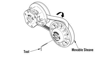
DRIVE CLUTCH/DRIVEN CLUTCH
ALIGNMENT — The alignment between the drive clutch and driven clutch are set at the factory. Normally, no adjustment is necessary; however, if premature drive belt wear or poor performance is experienced, the drive clutch/driven clutch alignment must be checked. TRACK TENSION AND ALIGNMENT — A certain amount of stretch occurs on all tracks during the first 500 miles. The track must be inspected/adjusted after the first 50 to 100 miles to the specifications given in the Track Specifications sub-section of this section and periodically thereafter. If these adjustments aren’t performed, the track may “derail” which leads to track and slide rail damage. Along with these major areas, other areas should be checked and adjusted. Below is a list of items to check after the break-in period. The recommended mileage for this inspection is between 100 and 300 miles.
Check drive clutch/driven clutch alignment Adjust track tension and alignment Check throttle cable tension Check engine idle Check coolant level Check chain case lubricant level Check engine oil Check and adjust chain tension (free-play) Check lights (high/low beam, brake light) Check safety switch operation Check engine compartment for any rubbing components Check steering hardware for tightness Check skid frame and A-arm mounting hardware for tightness Check brake lever travel and adjustment Grease all lubrication points
Engine Specifications
9000
ITEM
Engine Model Number 8KJ Displacement 998 cc Compression Ratio 9.0:1 Bore x Stroke 80.0 x 66.2 mm (3.15 × 2.61 in.) Cooling System Liquid Spark Plug (NGK) CR8E Spark Plug Gap 0.71-0.79 mm (0.028-0.031 in.) Piston Skirt/Cylinder Clearance 0.036-0.061 mm (0.0014-0.0024 in.) Piston Pin Diameter 20.990-20.995 mm (0.8264-0.8266 in.) Piston Pin Bore Diameter 21.004-21.015 mm (0.8269-0.8274 in.) Piston Pin to Piston Pin Bore Clearance 0.009-0.025 mm (0.0003-0.0009 in.) Connecting Rod: Small End Diameter 21.005-21.027 mm (0.8269-0.8278 in.) Crankshaft Pin/Connecting Rod: Big End 0.030-0.048 mm Clearance (0.0012-0.0019 in.) Connecting Rod: Big End Diameter 41.000-41.018 mm (1.6142-1.6149 in.)
Piston Ring End Gap (Top) (2nd) (Oil) Piston Ring/Groove Clearance (1st/Top) (2nd) (Oil) 0.35-0.45 mm (0.014-0.018 in.) 0.75-0.85 mm (0.030-0.033 in.) 0.10-0.35 mm (0.004-0.014 in.) 0.030-0.065 mm (0.0012-0.0026 in.) 0.020-0.055 mm (0.0008-0.0022 in.) 0.040-0.140 mm (0.0016-0.0055 in.)
Piston Diameter (10 mm from bottom edge)
79.95-79.96 mm (3.1476-3.1480 in.) Cam Lobe Height ( Intake) 33.750-33.850 mm (1.3287-1.3327 in.) (Exhaust) 33.750-33.850 mm (1.3287-1.3327 in.) Cam Lobe Width (Intake/Exhaust) 24.950-25.050 mm (0.9823-0.9862 in.) Camshaft Journal Diameter 24.46-24.47 mm (0.9630-0.9635 in.) Camshaft Journal Clearance 0.028-0.062 mm (0.0011-0.0024 in.) Crank Pin Diameter 37.976-38.000 mm (1.4951-1.4961 in.) Crankshaft Runout (max) 0.3 mm (0.012 in.) Crankshaft Main Bearing Clearance 0.027-0.045 mm (0.0011-0.0018 in.) Crankshaft/Rod Bearing Clearance 0.030-0.048 mm (0.0012-0.0019 in.)
Valve Clearance — Cold (Intake) (Exhaust) Valve Stem Diameter (Intake) (Exhaust) 0.15-0.22 mm (0.0059-0.0087 in.) 0.21-0.25 mm (0.0083-0.098 in.) 4.475-4.490 mm (0.1762-0.1677 in.) 4.460-4.475 mm (0.1756-0.1762 in.)
Valve Guide Inside Diameter (Intake) (Exhaust)
4.500-4.512 mm (0.1772-0.1776 in.) 4.500-4.512 mm (0.1772-0.1776 in.) Valve Guide/Stem Clearance (Intake) 0.010-0.037 mm (Exhaust) (0.0004-0.0015 in.) 0.025-0.052 mm (0.0010-0.0020 in.) Valve Face Width (Intake/Exhaust)0.90-1.10 mm (0.035-0.043 in.) VALVE TIMING (below) Intake Open (BTDC) 35.0 degrees Intake Closed (ABDC) 45.0 degrees Exhaust Open (BBDC) 45.0 degrees Exhaust Closed (ATDC) 35.0 degrees Valve Overlap 70.0 degrees
Electrical Specifications
(Normally Closed Ignition) Component Test Value + Test Connections -
Magneto Coil (3 tests)* 0.15-0.23 ohm white white Primary Ignition Coil* 1.19-1.61 ohms Secondary Ignition Coil* 8500-11,500 ohms Crankshaft Position Sensor 336-504 ohms blue/white green/white Voltage Regulator/Rectifier* 12-14.5 DC Volts terminal terminal Magneto Coil (no load) 36-44 AC Volts white white Ignition Switch Less than 1 ohm (key in ON position) terminal terminal * Harness plugged in NOTE: Lighting coil output is unregulated voltage. ! WARNING
Most voltages generated by the ignition system are sufficient to interrupt pacemakers! All technicians, especially those using pacemakers, must avoid contact with all electrical connections when pulling the recoil starter rope or after the engine has been started.
Drive System Specifications
Drive Clutch/Driven Clutch-Related Specifications Drive System Components
Model Altitude Drive Clutch Spring Cam Arm Driven Clutch Spring Torque Bracket Drive Belt Engagement RPM Peak RPM Top Gear Bottom Gear Chain Pitch
ZR 9000 Thundercat n/a 120/285 lb J14-74g 155-220 lb58-49-.150627-112 4-4200 8750 24T 50T 92 ZR 9000 Thundercat (OS) n/a 120/285 lb J14-74g 155-220 lb58-49-.150627-112 4-4200 8750 22T 48T 90
ALIGNMENT BAR Offset P/N Center-to-Center Offset Float
0744-097 10.38” ± 0.020” 1.500” None A list of drive system components that are available through the Arctic Cat Service Parts Department can be found in the POGA Reference Guide. This information will be useful when doing any fine-tuning on the drive system.
Track Specifications
Drive Sprocket
9 Tooth (2.86" pitch) 21 49 0.429 90 73 75 77 80 82 84 87 89 91 94 96 98 101 103 105 20 46 0.435 88 74 76 78 81 83 85 88 90 93 95 97 100 102 104 107 23 51 0.451 92 76 79 81 84 86 89 91 94 96 98 101 103 106 108 111 22 48 0.458 90 78 80 83 85 88 90 93 95 98 100 103 105 108 110 113 24 50 0.480 92 81 84 86 89 92 94 97 100 102 105 107 110 113 115 118 21 41 0.512 86 87 89 92 95 98 101 103 106 109 112 115 117 120 123 126 21 38 0.553 84 93 97 100 103 106 109 112 115 118 121 124 127 130 133 136 20 35 0.571 82 97 100 103 106 109 112 115 118 122 125 128 131 134 137 140 23 40 0.575 86 97 100 104 107 110 113 116 119 122 126 129 132 135 138 141 22 37 0.595 84 101 104 107 110 114 117 120 123 127 130 133 136 140 143 146 24 39 0.615 86 104 107 111 114 118 121 124 128 131 134 138 141 144 148 151 23 36 0.639 84 108 112 115 119 122 126 129 132 136 139 143 146 150 153 157 24 35 0.686 84 116 120 123 127 131 135 138 142 146 150 153 157 161 165 168
Gear Ratio Ratio Chain Engine RPM
TopBtm 6200 6400 6600 6800 7000 7200 7400 7600 7800 8000 8200 8400 8600 8800 9000 Vehicle Speed (mph)
Model Length Lug Height
ZR 9000 Thundercat 137” 1.0”/1.75”
NOTE: The track tension should be 20 lb @ 2 in.
IFP Shock Specifications
Below is a list of IFP shock absorbers used on the front and rear suspensions of Arctic Cat snowmobiles. If replacing a shock absorber, always select a shock absorber with the same length, both collapsed and extended.
FRONT ARM Model Collapsed Length Extended Length Stroke Piston Depth
ZR 9000 Thundercat 8.55” 12.49” 3.94” 5.55”
ft-lb N-m ft-lb N-m ft-lb N-m ft-lb N-m
1 1.4 26 35.4 51 69.4 76 103.4 2 2.7 27 36.7 52 70.7 77 104.7 3 4.1 28 38.1 53 72.1 78 106.1 4 5.4 29 39.4 54 73.4 79 107.4 5 6.8 30 40.8 55 74.8 80 108.8 6 8.2 31 42.2 56 76.2 81 110.2 7 9.5 32 43.5 57 77.5 82 111.5 8 10.9 33 44.9 58 78.9 83 112.9 9 12.2 34 46.2 59 80.2 84 114.2 10 13.6 35 47.6 60 81.6 85 115.6 11 15 36 49 61 83 86 117 12 16.3 37 50.3 62 84.3 87 118.3 13 17.7 38 51.7 63 85.7 88 119.7 14 19 39 53 64 87 89 121 15 20.4 40 54.4 65 88.4 90 122.4 16 21.8 41 55.8 66 89.8 91 123.8 17 23.1 42 57.1 67 91.1 92 125.1 18 24.5 43 58.5 68 92.5 93 126.5 19 25.8 44 59.8 69 93.8 94 127.8 20 27.2 45 61.2 70 95.2 95 129.2 21 28.6 46 62.6 71 96.6 96 130.6 22 29.9 47 63.9 72 97.9 97 131.9 23 31.3 48 65.3 73 99.3 98 133.3 24 32.6 49 66.6 74 100.6 99 134.6 25 34 50 68 75 102 100 136
Torque Conversions
Torque Specifications
NOTE: Torque specifications have the following tol-
erances:
Torque (ft-lb) Tolerance
0-15 ±20% 16-39 ±15% 40+ ±10%
Item
Secured to Torque ft-lb DRIVE SYSTEM
Drive Clutch Engine 51 Drive Clutch Cover Movable Sheave 120 in.-lb Cam Arm Lock Nut Cam Arm Screw 50 in.-lb Driven Clutch Driven Shaft 60 Movable Sheave Torque Bracket 72 in.-lb Chain Case (Cap Screw) Chassis 96 in.-lb Chain Case (Torx-Head Screw) Chassis 12 Chain Case Cover Chain Case 12 Shift Actuator Chain Case Cover 36 in.-lb Brake Caliper Chassis 25* Outside Caliper Housing Inside Caliper Housing 25 Brake Line Caliper 25 Brake Line Master Cylinder 25 Brake Caliper Shield Cover 96 in.-lb*
STEERING/FRONT SUSPENSION/CHASSIS
Ski Spindle 35 Ski Wearbar 8 Ski Ski Handle 54 in.-lb Handlebar Adjuster Block Post 15 Steering Support Mounting Block 8 Steering Tie Rod Link Steering Post 35 Steering Tie Rod Link Steering Arm 20 Steering Post Cap Riser Block 15 Steering Post Chassis 55 Steering Tie Rod Steering Arm 20 Tie Rod Spindle Arm 32 Steering Support Spar 20 Steering Arm Chassis 8 A-Arm (Upper) Chassis 23 A-Arm (Lower) Chassis (Front) 65 A-Arm (Lower) Chassis (Rear) 45 A-Arm (Upper) Spindle 23 A-Arm (Lower) Spindle 45 Shock Absorber Spindle 32 Shock Absorber Chassis 32 Sway Bar Link A-Arm/Sway Bar Link 23 Sway Bar Mounting Bracket Chassis 9
REAR SUSPENSION
Wear Strip Rail 50 in.-lb End Cap Rail 80 in.-lb Mounting Block Rail 12 Rear Arm Rail 45 Rear Arm Idler Arm 55 Spring Slide Rail 20 Front Arm Rail 52 Coupler Block Axle Rail 40 Limiter Strap Rail Support 72 in.-lb Rear Wheel Axle Rail 34 Skid Frame Tunnel 45* Front Shock Rail 50* Rail Support Rail 20 Limiter Strap Front Arm 72 in.-lb