17 minute read
Engine-Related Items


NOTE: Whenever a part is worn excessively,
cracked, or damaged in any way, replacement is necessary.
SPECIAL TOOLS A number of special tools must be available to the technician when servicing the engine-related items. NOTE: When indicated for use, each special tool
will be identified by its specific name, as shown in the chart below, and capitalized.
NOTE: Special tools are available from the Arctic
Cat Service Parts Department.
Description p/n
Blind-Hole Bearing Puller 0644-500 Coolant Cap 0644-156 Drive Clutch Spanner Wrench 0644-136 Valve and Spring Retainer Tool 0644-448 Fan Spanner Wrench 0644-340 Water Pump Bearing and Seal Tool Kit 0644-557 Oil Seal Protector Tool 0644-219 Engine Leak-Down Test Kit 0644-522 Vacuum Test Pump 0644-131 Hood Harness Extension 1686-659 Hood Harness Extension 1686-660 Oil Filter Wrench 0644-551
Water Pump
! WARNING
When servicing the water pump, disconnect the negative battery cable to avoid injury.
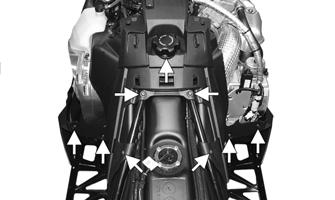
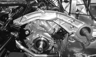
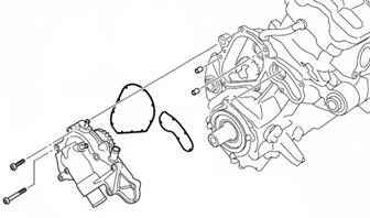
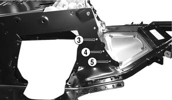
REMOVING 1.Drain the engine coolant. 2.Remove the drive clutch, drive belt, driven clutch and the clutch guard. 3.Remove the cap screws and nuts securing the left-side chassis support; then carefully tip the support up to gain clearance to the water pump. 4. Disconnect all hoses from the water pump; then remove the allen-head screws securing the water pump assembly to the crankcase; then remove the assembly. Account for two dowel pins and two gaskets.
SNO-278
DISASSEMBLING/ASSEMBLING
SNO-372
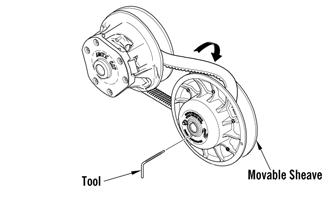
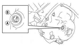
1.Obtain top-dead-center (TDC) by rotating the crankshaft (clockwise) until the mark on the magneto rotor is aligned with the pointer on the magneto cover and the #3 piston is at TDC.
SNO-279A
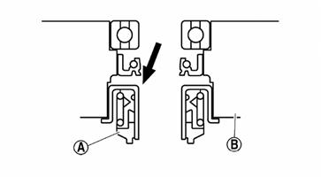
2.Remove the screws securing the water pump cover to the water pump; then remove the impeller. 3.Remove the water pump seal (A) from the water pump housing (B).
SNO-373A
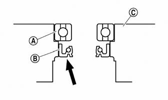
4.Remove the bearing (A) and the oil seal (B) from the water pump housing (C).
SNO-374A
5.Remove the rubber damper holder (A) and the rubber damper (B) from the impeller using a small flat-head screwdriver making sure not to damage the impeller shaft.
SNO-376A
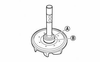
2.Install the bearing using a socket of the same diameter; then apply sealant to the water pump housing; then install the water pump seal using the mechanical seal installation tool.
3.Apply tab water or coolant to the impeller shaft; then press the rubber damper holder (A) and rubber damper (B) onto the impeller shaft.
CAUTION
Never apply oil or grease onto the water pump seal surface.
SNO-378A
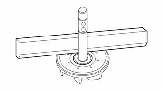
4.Using a straight edge, make sure the impeller is flush with the damper.
SNO-375A
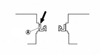
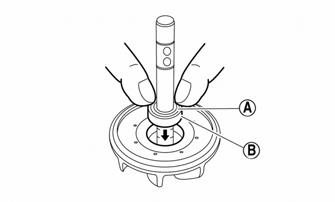
INSTALLING 1.Apply tap water or coolant to the outer surface of the new oil seal; then install the oil seal (A) into the water pump housing using a socket of the same diameter.
SNO-379
5.Install the impeller assembly into the housing and secure using the existing circlip. 6.With the engine still at Top-Dead-Center (TDC), install the water pump and secure using the existing screws. Tighten to 8.7 ft-lb. 7.Fill the cooling system.
Pressure Testing Engine
NOTE: To pressure test the engine, use Engine
Leak-Down Test Kit.
Checking Compression
NOTE: Prior to this test procedure, verify the bat-
tery is fully charged and the console is positioned over the support bracket with the hood/main harness plugged in.
NOTE: This test must be done with the engine at
operating temperature and “full-cranking RPM” and the decompression system active.
With the spark plugs removed, install the compression tester gauge with adapter into the spark plug hole; then with the throttle valve in the full-open position, crank the engine over to get the psi reading. Compression should be 213.3 psi
CAUTION
Do not ground the spark plug on the cylinder head cover. The cover is made of magnesium and any contact with spark or electrical arc will severely pit the surface.
NOTE: Verify both cylinder compression readings
are within 10% of each other.
Changing Oil/Filter
! WARNING
Engine oil is extremely hot immediately after the engine is turned off. Burning could occur if oil contacts skin or clothing.
NOTE: Recycle or properly dispose of the used
engine oil.
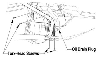
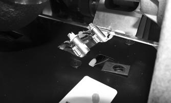
1.Park the snowmobile on a level surface; then start the engine and let it idle and warm up until it reaches operating temperature, or if the snowmobile was operated, allow the engine to idle for approximately 30 seconds. Shut off the engine. 2.Remove the Torx-head screws and the rear access plate from beneath the snowmobile. 3.Place a drain pan beneath the engine oil drain screw; then remove the screw and allow the oil to drain completely.
YM-152A
4.Using Oil Filter Wrench, loosen (but do not remove) the oil filter and allow the oil to drain from the filter into the drain pan; then remove the filter making sure the O-ring is removed with the filter. 5.Apply a light coat of fresh engine oil to the seal of the new oil filter. 6.Install the new oil filter by turning the oil filter by hand until the seal has contacted the oil filter mounting surface; then tighten the oil filter to 12 ft-lb. 7.Install the engine oil drain screw with a new gasket.
Tighten the screw to 7.2 ft-lb. 8.Install the rear access plate. Tighten the screws to 9 ft-lb. 9.Remove the four Torx-head screws securing the right-side footrest to the tunnel and the support; then with a drain pan in position, remove the drain plug from the oil tank.
746-121A
NOTE: To aid in draining the oil from the tank,
position a funnel between the tank and the opening of the tunnel running board.
10.After the oil has drained completely, install the drain plug with a new O-ring and tighten to 16 ft-lb. 11.Install the four screws securing the right-side footrest. Tighten the screws to 44 in.-lb. 12.Pour 2.8 L (3 US quarts) of engine oil in through the oil tank fill hole.
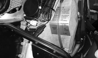
13.Install the oil tank plug then start the engine and let it idle. The oil pressure warning icon may illuminate briefly after starting but should go out within 10 seconds. If the icon does not go out within 10 seconds, the engine will automatically shut down. If a shutdown occurs, check that there are no leaks and that oil has been added to the oil tank before trying to start the engine again. If the engine shuts down automatically, the key will have to be turned off for 5 seconds before the engine can be restarted. 14.Shut the engine off; then allow the engine to cool; then look at the oil level tube on the backside of the oil tank. The oil should be above the MIN line but not above the MAX line.
XM451
15.If steps 13 and 14 were followed and the oil level is not within the “MAX to MIN” range, add the recommended engine oil through the oil tank fill hole. NOTE: Care must be taken not to over-fill the oil
tank.
16.Install the oil fill plug.
Liquid Cooling System
The liquid cooling system consists of a heat exchanger, water pump, and thermostat. The system should be inspected for leaks or damage whenever an overheating problem is experienced. DRAINING COOLING SYSTEM 1.Remove both access panels and the hood; then using a vacuum pump, remove as much coolant as possible from the coolant filler neck. 2.Remove the exhaust resonator; then remove the resonator. 3.Remove the hose clamp from the coolant hose connecting the water pump to the right side of the heat exchanger. With a drain pan positioned under the coolant hose, remove the hose from the water pump and tip the hose downward allowing the coolant to drain completely. 4.Apply 0.35-0.56 cm² (5-8 psi) to the coolant system through the coolant overflow tube and continue until the coolant stops draining from the system. FILLING/BLEEDING COOLING SYSTEM NOTE: The snowmobile should be on level ground
for this procedure.
1.Remove the access panels and hood. 2.Place the hood alongside the snowmobile; then using
Hood Harness Extension, connect the hood to the main harness. 3.Add coolant into the filler neck until coolant is visible at the bottom of the filler neck.
SNO-867
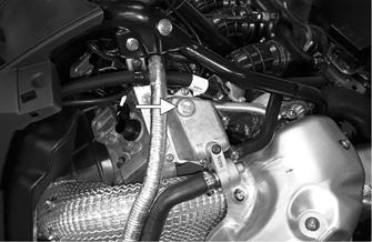
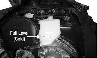
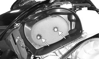
4.Locate the coolant tank above the secondary sheave; then remove the plug from the coolant tank. Add coolant to the full level on the tank. Install the plug.
XM452A
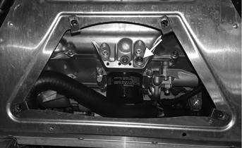
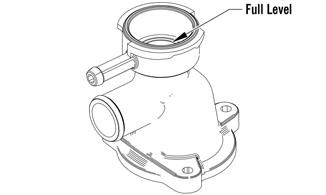
5.Remove the plug in the vapor tank located above the exhaust. Once the plug is removed, verify the coolant is just below the threads. If coolant needs to be added, add coolant to the bottom of the threads.
Install the plug.
6.Start the engine and allow it to run for five minutes.
Then shut off engine. 7.Let the engine cool to allow the coolant level in the filler neck to drop; then add coolant into the filler neck until no air is visible or heard. Add coolant to the coolant tank, if necessary.
8.Start the engine and allow it to run for five minutes; then shut the engine off and allow it to cool. 9.Repeat steps 4-5 at least two more times (more if necessary) until no air is in the cooling system.
CAUTION
Running the engine with low coolant level can cause severe engine damage.
10.Install the hood and both access panels. INSPECTING COOLANT HOSES AND CLAMPS All coolant hoses and connections should be checked annually for deterioration, cracks, and wear. All coolant hoses and clamps should be replaced every four years. INSPECTING THERMOSTAT 1.Inspect the thermostat for corrosion, wear, or spring damage. 2.Using the following procedure, inspect the thermostat for proper operation.
A.Suspend the thermostat in a container filled with water; then heat the water and monitor the temperature with a thermometer.
B.The thermostat should open at 75° C (167° F). Once the thermostat starts to open, and allow it to cool down verifying it has returned to the fully closed position.
CAUTION
Never heat the thermostat to the fully open position or damage to the thermostat may occur.
Cooling System Schematic
The following schematic is representative of the style of cooling system in this snowmobile.
0750-386
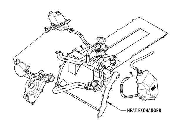
Heat Exchanger
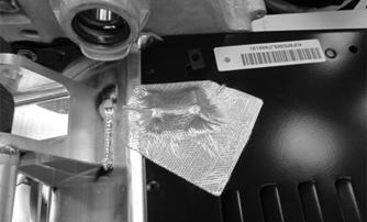
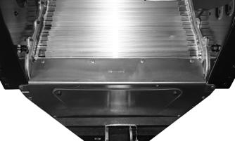
Certain models are equipped with a two-piece heat exchanger for easier rear exchanger serviceability. The access panels, hood, and the gas tank will have to be removed for this process. REMOVING
1.Remove the foil covering the right-side coolant hose and clamps.
YM-216
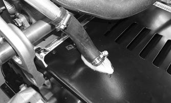
2.Loosen the hose clamps securing the rear heat exchanger.
YM-194
YM-195
3.Remove the rivets securing the rear heat exchanger to the tunnel. When installing the front heat exchanger to the tunnel it is important to follow the sequence below for proper installation.
1.Position the heat exchanger mounting holes with the holes in the tunnel; then secure the PTO-side of the exchanger using two rivets in the order shown below.
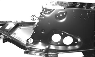
XM544A
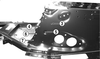
2.Secure the MAG-side of the exchanger along with the bottom resonator bracket (not shown) using three rivets in the order shown below.
XM545A
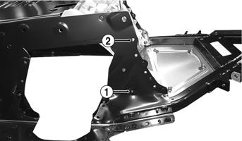
3.Secure the PTO-side of the exchanger to the tunnel in the order shown below.
XM544B
XM545B
5.Secure the bottom of the heat exchanger using four rivets.
YM-199
6.Secure the top of the heat exchanger using four rivets.
7.Position the retaining plate on the left side of the tunnel and secure using the existing cap screw; then secure using two rivets. Remove the cap screw. 8.Position the rear exchanger with the mounting locations in the tunnel; then with the hoses connecting the front and the rear in position, secure the exchanger to the tunnel using the appropriate number of rivets. 9.Tighten the hose clamps to 35 in.-lb; then apply silicone around the holes in the tunnel.
YM-194 YM-195
10.Cover the right-side coolant hose and clamps using a new piece of protective foil.
YM-216
Air Silencer
REMOVING/INSTALLING The air filter inside the air filter housing must be clean to provide good engine power and gas mileage. If operating the snowmobile in deep powder conditions, the air filter should be inspected for snow buildup. 1.Remove the left-side access panel; then remove the clips securing the air filter housing cover.
XM470A
2.Loosen the two knobs securing the air filter to the inside of the housing; then remove the filter.
XM471A
3.Install the filter and secure using the two knobs; then secure the cover using the clips. 4.Install the left-side access panel.
Turbocharger/Intercooler
! WARNING
The rotating components in a turbocharger turn at speeds of 150,000 RPM. Any imbalance could cause rapid disintegration resulting in bodily injury or death. Always handle a turbocharger in accordance with the manufacturer’s recommendations.
CAUTION
Do not drop the turbocharger. If dropped, it must be replaced.
CAUTION
Do not touch rotating parts as damage to turbine or compressor blades may occur.
CAUTION
Do not carry the turbocharger by the hoses or by the waste gate control rod. Damage could occur.
CAUTION
Do not run a turbocharged engine with the intake hose removed from the compressor inlet. Dirt, foreign objects, or loose clothing can be ingested causing turbocharger failure and engine damage.
CAUTION
Do not spin the turbocharger with compressed air as bearings will be damaged.
CAUTION
Do not store the turbocharger vertically as oil will be lost from the bearing cavity and bearing damage on start-up could occur.
Turbocharging is one method of compensating for loss of air density that works extremely well when applied to four-cycle internal combustion engines. Exhaust gasses are directed through the turbocharger turbine wheel which is attached to the compressor through a common shaft. As the exhaust gasses spin the turbine, the compressor is spun at very high RPM. Inlet air is drawn into the compressor, compressed, and routed to the intake manifold of the engine. Intake pressure, therefore, is maintained at the optimum level as altitude or temperature increases.

The turbocharger output must be regulated to maintain the optimum manifold pressure throughout the designed operating range. This is accomplished by regulating the volume of exhaust gasses passing through the turbine by controlling a diverter valve (waste gate) at the turbocharger turbine inlet. At lower altitudes/temperatures, excessive exhaust gasses are diverted past the turbine and into the exhaust downstream of the turbocharger thus limiting the compressor output to maintain correct manifold pressure. As altitude increases, the manifold pressure is held constant by diverting less exhaust past the turbine, thus increasing compressor speed. This will continue until the waste gate is completely closed at which time manifold pressure will start to decrease much the same as a normally aspirated engine. The waste gate is controlled by a spring/diaphragm mechanism that is connected to the intake manifold by an air line. A mechanical linkage connects the diaphragm to the waste gate control arm. Air is heated by friction and compression through the turbocharger and air density is lost by heating the air; therefore, an after-cooler is installed between the turbocharger compressor and the intake manifold. This is an air-to-air after-cooler that uses outside air directed through a radiator-type cooler to cool the compressed air prior to entering the intake manifold. REMOVING
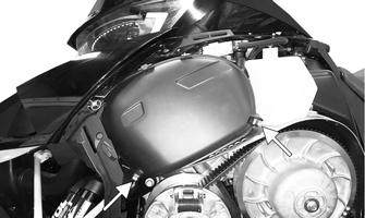
The oil and coolant should be drained before removing the turbocharger. 1.Remove both access panels; then loosen the two quarter-turns securing the hood. Disconnect the hood harness and pull the hood forward and off of the snowmobile. 2.Remove the seat; then remove the gas cap and retaining nut from the neck of the gas tank. Remove the eight screws securing the console. Remove the console.
YM-176A
3.Remove the gas tank assembly.
YM-181
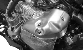
5.Remove the cap screws and washers securing the heat shield to the manifold.
YM-155
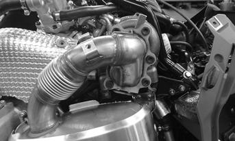
6.Apply a small amount of penetrating lubricant to the threads of the clamps; then remove the two nuts securing the exhaust pipe clamps. Remove the clamps and the pipe.
YM-182A
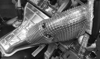
7.Remove the six Torx screws securing the resonator to the turbo; then remove the spring securing the resonator. Remove the resonator and account for a gasket. NOTE: Apply a small amount of penetrating oil to
the Torx screws before removing the screws. Disassemble with hand tools and T50 ball head Torx bit (p/n 0644-623).
YM-154
8.Remove the hose clamps securing hoses to the turbo.
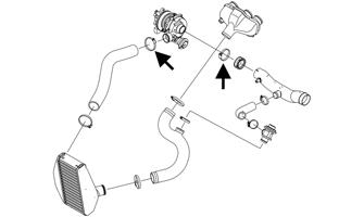
SNO-835B
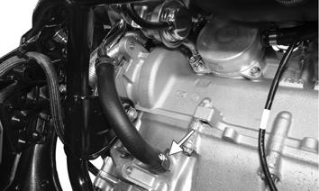
9.Remove the hose clamp securing the coolant hose to the vapor tank; then remove the hose clamp securing the coolant hose from the bottom of the turbo.
YM-164
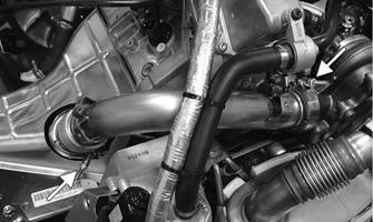
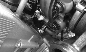
10.Remove the clamp securing the oil return hose to the crankcase; then remove the oil delivery hose to the cylinder head.
YM-165A YM-163
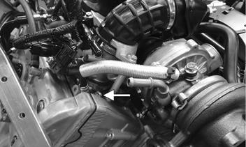
YM-163
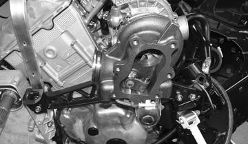
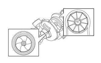
11.Remove the cap screws and nuts securing the right-side chassis support to the chassis. Remove the turbo and support assembly. INSPECTING 1.Inspect the turbine (exhaust) blades for any signs of wear or damage; then inspect the compressor (intake) blades. 2.Connect the lower coolant hose on the backside of the turbo to the oil cooler. Secure using the existing hose clamp. Tighten to 35 in.-lb.
YM-164
3.Secure the oil return hose to the crankcase using the existing clamp; then secure the oil delivery hose to the cylinder using the existing banjo bolt and new washers. Tighten to 7.2 ft-lb.
NOTE: If any damage to the compressor or turbine blades is present, the turbocharger must be replaced.

SNO-846
2.Inspect the waste gate linkage for signs of wear or damage. 3.Inspect the positive pressure hose for signs of cracks and damage. Replace as necessary. INSTALLING
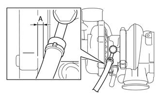
1.With the turbo installed onto the MAG-side mounting bracket using the existing cap screws. Tighten to 50 ft-lb. Secure the assembly to the chassis using the existing screws and nuts. Tighten to 12 ft-lb.
YM-165A
YM-163
NOTE: Make sure the distance (A) between the oil
delivery hose and the turbo is 3.0 mm (0.12 in.).
SNO-821
4.Install the intercooler hose to the turbo; then install the intake duct to the turbo using the existing clamps.
Tighten to 35 in.-lb.
SNO-835B
5.Position the exhaust gasket between the turbo and the resonator; then using the long T50 ball head Torx bit, secure the resonator to the turbo using the existing screws. Tighten the screws to 9 ft-lb then to 18 ft-lb in a crisscross pattern. NOTE: Apply a small amount of high temperature
copper based anti-seize lubricant to the threads of the screws. Assemble with hand tools and T50 ball head Torx bit (p/n 0644-623).
YM-154
6.Install the exhaust pipe onto the exhaust manifold and the turbo and secure using the existing clamps.
Tighten to 6.1 ft-lb.
YM-182A
7.Install the exhaust heat shield to the exhaust pipe using the existing cap screws and washers. Tighten securely.
YM-155
8.Install the turbo heat shield and secure using the existing cap screws and washers. Tighten securely.