15 minute read
Fuel Systems


This section has been organized for servicing the fuel systems; however, some components may vary from model to model. The technician should use discretion and sound judgment when removing/disassembling and assembling/installing components. Whenever any maintenance or inspection is made on the fuel system where fuel leakage may occur, there should be no welding, smoking, or open flames in the area.
WARNING
Since the fuel supply hose may be under pressure, remove it slowly to release the pressure. Place an absorbent towel around the connection to absorb gasoline; then remove the hose slowly to release the pressure. Always wear safety glasses when removing the fuel hoses.
NOTE: Whenever a part is worn excessively,
cracked, or damaged in any way, replacement is necessary.
SPECIAL TOOLS A number of special tools must be available to the technician when servicing the fuel systems. NOTE: When indicated for use, each special tool
will be identified by its specific name, as shown in the chart below, and capitalized.
NOTE: Special tools are available from the Arctic
Cat Service Parts Department.
Description p/n
EFI Analyzer 0744-049 EFI Diagnostic System Manual 2257-850 EFI Diagnostic System Manual (Instructions) 2259-020 Fluke Model 77 Multimeter 0644-559 Fuel Hose Clamp Tool 0644-545 Fuel Pressure Test Kit 0644-493 Vacuum Test Pump 0644-131 Fuel Pump Installation Tool Kit 0744-074 Laptop Diagnostic Test Kit 0744-050 Laptop Diagnostic Tool 0744-060 Oil Injection Usage Tool 0644-007
Fuel System
INTRODUCTION The Arctic Cat EFI System operates off a series of coils located on the stator and is made up of the following components. An engine control module (ECM) calculates input from sensors (air temperature sensor, coolant temperature sensor, throttle position sensor, and a knock sensor) to provide the engine with the correct fuel mixture and timing for optimum operation.
FUEL SYSTEM The fuel is first drawn into the electric fuel pump through multiple pick-up valves and hoses. The fuel is then routed through a high-pressure fuel hose to the fuel rail. The fuel pressure is maintained in the fuel rail by the fuel regulator. With the fuel pressure maintained at a constant psi, the ECM evaluates the information it receives from the electrical sensors and opens the injectors for precise periods of time (pulse widths) to meet engine demands.
Individual Components
ECM The ECM is the brain of the EFI system. It uses sensor inputs to determine the correct fuel/air ratio for the engine given the existing conditions of altitude and temperature.
If any of the sensors should fail while the engine is running, the ECM will sense a problem and go into a “fail safe” mode. This is an over-rich condition and will greatly reduce performance. However, the engine will be protected from a possible lean condition and engine damage. The ECM is equipped with a self-diagnostic system utilizing the service icon in the speedometer/tachometer and remains illuminated when a problem exists with any of the sensors. The technician can determine the problem sensor by reading the code shown on the readout screen and applying it to the ECM Diagnostic Codes chart (see Self-Diagnostic System/Codes in this section).
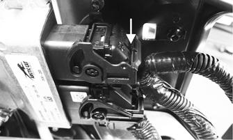
Removing 1.Remove both access panels; then remove the hood. 2.Remove the air intake assembly from the throttle body and the radiator. 3.Press the retaining tabs on the ECM connectors in; then rotate the connector arms up while will allow the connectors to be released from the ECM.
YM-052
4.Remove the four cap screws and nuts securing the
ECM to the chassis.
SNO-830
Installing 1.Secure the ECM to the chassis using the existing four nuts. Tighten securely; then press the two connectors into the ECM and rotate the connector arm down until it locks.
NOTE: Make sure all connectors are clean and
tight. Apply dielectric grease to all connector seals.
2.Install the air intake assembly to the throttle body and the radiator.
3.Install the hood and access panels.
AIR TEMPERATURE SENSOR This sensor detects air temperature entering the air silencer and engine. The ECM sends current to this sensor, and (depending on the temperature) the sensor will pass a certain amount of current through the sensor to ground. The ECM measures how much current passes through the sensor to ground. From this measurement, the ECM determines the air temperature and calculates the fuel/air mixture ratio. Resistance will drop as the temperature rises.
Removing 1.Disconnect the wiring harness from the air temperature sensor.
2.Using a flat-blade screwdriver, pry the sensor end to end to remove it from the air silencer. Account for two push pins. NOTE: The sensor is secured to the air intake
assembly using two screws.
Installing 1.Place the sensor into position in the air silencer and secure with push pins. NOTE: Secure the sensor using two screws. Tighten
securely.
2.Connect the wiring harness to the air temperature sensor. Secure the sensor wires with cable ties so they do not rub on any other components.
COOLANT TEMPERATURE SENSOR This sensor detects coolant temperature. The ECM measures the current flow through the sensor to ground. From this measurement, the ECM can determine the engine coolant temperature and calculate the correct fuel/air mixture ratio. If the coolant temp rises above 105°C (221°F) the temp light on the gauge will start to flash and the engine will go into a fuel cut (surging) mode to alert the rider of overheating. If the temp continues to rise and exceeds 110°C (230°F) the temp light will be on continuously. The fuel cut will not protect the engine from overheating if the operator continues to ride the snowmobile.
THROTTLE POSITION SENSOR This sensor is a potentiometer (essentially, a resistor). This sensor transforms the throttle-valve position into output voltage to the ECM. In addition, the sensor detects the opening or closing speed of the throttle valve and feeds that rate of voltage change to the ECM. The input from the throttle position sensor is one of the main inputs for the ECM calculation of fuel/air mixture ratio.
IGNITION TIMING SENSOR This sensor is triggered by teeth precisely mounted to the flywheel flange. Each time a tooth rotates past the sensor, a signal is sent to the ECM. From this signal, the ECM determines ignition and injection timing and RPM.
BAROMETRIC PRESSURE SENSOR This sensor reads atmospheric pressure. From this information, the ECM determines the correct fuel/air mixture ratio.
FUEL INJECTORS A fuel injector is an electromagnetic injection valve controlled by a signal from the ECM. The coil used in the injector is a high-pressure resistance type. The ECM determines the optimum fuel injection time and duration based on signals from the sensors. When voltage is sent to the fuel injector, it energizes the coil and opens the needle valve, thereby injecting fuel. Because the fuel pressure (pressure differential between fuel line and manifold) is kept constant, the amount of fuel injected is determined by the duration of time the valve is open and manifold pressure.
Removing
WARNING
Since the fuel supply hose may be under pressure, remove it slowly to release the pressure. Place an absorbent towel around the connection to absorb gasoline; then remove the hose slowly to release the pressure. Always wear safety glasses when removing the fuel hoses.
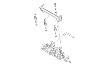
1.Remove the orange clamp securing the fuel supply hose to the fuel rail.
2.Disconnect the wiring harness from each injector. 3.Remove the cap screws and washers securing the fuel rail to the throttle body assembly; then remove the rail from the injectors. Account for two washers and two spacers.
SNO-369
4.Remove the fuel injectors from the throttle body assembly. Account for six grommets.
Installing 1.Apply a light coat of oil to all six grommets; then install onto each injector. 2.Install the injectors into the throttle body assembly. 3.Place the fuel rail into position on top of the injectors and secure with existing spacers, washers and cap screws.
SNO-369
4.Connect the fuel delivery hose to the fuel rail and secure with the orange clamp. 5.Connect the wiring harness to the injectors. Cable tie as needed.
CRANKSHAFT POSITION SENSOR This sensor measures the location in degrees of rotation of the crankshaft. A 15° resolution exists between signals. The signal is triggered by teeth on the outer surface of the flywheel as they pass by the sensor. The sensor gives the ECM the location of the crankshaft at a given point in time. The ECM processes the information and uses it in many different types of calculations. For example, the sensor can be used for RPM, and it can also be used to determine the rate of acceleration of the crankshaft.
MANIFOLD ABSOLUTE PRESSURE (MAP) SENSOR This sensor measures pressure in the intake manifold when the engine is running. The ECM uses this sensor to aid in calculating the required fueling. For the base fuel map, the snowmobile relies on the MAP sensor only for low throttle openings. After a given throttle opening is reached, the ECM switches to the TPS sensor for its main fuel map. The ECM uses the MAP sensor for many other calculations, but the base fuel map is the main one.
Self-Diagnostic System/Codes
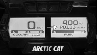
The Diagnostic Code Alarm is controlled by the ECM. If a code and the word ALARM illuminates while the engine is running, the ECM is receiving input that is outside of its established parameters. Refer to the following chart.
CWI-105A
Code Trouble
P0016 Crankshaft Position — Camshaft Position Correlation P0107 Manifold Absolute Pressure Circuit Low P0108 Manifold Absolute Pressure Circuit High P0112 Intake Air Temperature Sensor Circuit Low P0113 Intake Air Temperature Sensor Circuit High P0114 Intake Air Temperature Sensor Circuit Intermittent P0115 Engine Coolant Temperature Sensor 1 Circuit P0117 Engine Coolant Temperature Sensor 1 Circuit Low P0118 Engine Coolant Temperature Sensor 1 Circuit High P0119 Engine Coolant Temperature Sensor 1 Circuit Intermittent P0120 Throttle Position Sensor Circuit P0121 Throttle Position Sensor Circuit Range Performance P0122 Throttle Position Sensor Circuit Low P0123 Throttle Position Sensor Circuit High P0201 Injector Circuit/Open — Cylinder 1 P0202 Injector Circuit/Open — Cylinder 2 P0203 Injector Circuit/Open — Cylinder 3 P0217 Engine Coolant Over Temp Condition P0261 Cylinder 1 Injector Circuit Low P0262 Cylinder 1 Injector Circuit High P0264 Cylinder 2 Injector Circuit Low P0265 Cylinder 2 Injector Circuit High P0267 Cylinder 3 Injector Circuit Low P0268 Cylinder 3 Injector Circuit High P0340 Camshaft Position Sensor “A” Circuit P0500 Vehicle Speed Sensor “A” P0508 Idle Air Control System Circuit Low
P0509 Idle Air Control System Circuit High P0511 Idle Air Control Circuit P0522 Engine Oil Pressure Sensor Circuit Low P0523 Engine Oil Pressure Sensor Circuit High P0562 System Relay Voltage Low P0563 System Relay Voltage High P0642 Sensor Reference Voltage “A” Circuit Low P0643 Sensor Reference Voltage “A” Circuit High P0780 Shift Error P0919 Gear Shift Position Control Error P1315 Crankshaft Position Out of Sync P1338 Crankshaft Spike Detected P1339 Crankshaft Tooth Number Detection Error P1685 Main Relay Open Circuit P1686 Main Relay Circuit Low P1687 Main Relay Circuit High P1688 Reverse Relay Open Circuit P1689 Reverse Relay Circuit Low P1690 Reverse Relay Circuit High P1691 Forward Relay Open Circuit P1692 Forward Relay Circuit Low P1693 Forward Relay Circuit High P1694 Headlight Relay Open P1695 Headlight Relay Low P1780 Shift Switch Stuck P2228 Barometric Pressure Sensor A Circuit Low P2229 Barometric Pressure Sensor A Circuit High P2282 Air Leak between Throttle Body and Intake Valves P2300 Ignition Coil “A” Primary Control Circuit Low P2301 Ignition Coil “A” Primary Control Circuit High P2303 Ignition Coil “B” Primary Control Circuit Low/Open P2304 Ignition Coil “B” Primary Control Circuit High P2306 Ignition Coil “C” Primary Control Circuit Low P2307 Ignition Coil “C” Primary Control Circuit High U0155 Lost Communication with ECM U1000 Vehicle Not Registered or Invalid PIN U1001 Vehicle Not Registered and Vehicle Limits Enabled
Fuel Pressure Regulator
1.Using the Fuel Pressure Test Kit, connect the tester to the regulator fuel inlet. NOTE: A short piece of 3/8 in. I.D. hose will be
needed to make the above connections.
2.Pressurize the regulator to 28-31.3 psi. Turn the pressure tester shut off valve to the OFF position.
Observe the gauge for several minutes and note any loss of pressure. If pressure begins to drop, the cause may be a ruptured diaphragm, worn spring, or leaking valve. If the regulator fails to build or maintain pressure, replace the regulator. NOTE: If the pressure drops, check the hose con-
nections to ensure no leaks exist.
REMOVING 1.Loosen the throttle cable from the bracket; then remove the throttle cable from the pulley on the throttle body lever shaft. 2.Remove the cable ties securing the throttle cable. 3.Remove the throttle cable ends from the throttle lever and from the throttle control housing.
INSTALLING/ADJUSTING 1.Install the throttle cable into the throttle control assembly making sure the cable snaps into place. 2.Install the throttle cable end on the throttle lever.
3.Route the throttle cable from the throttle control assembly to the throttle body assembly and oil-injection pump; avoid any sharp bends or moving components.
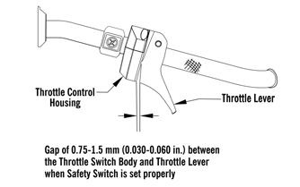
4.Attach the throttle cable to the pulley on the throttle body shaft. 5.Secure the throttle cable to the handlebar and steering post with cable ties. 6.Adjust the throttle cable tension by turning the jam nuts in the appropriate direction until 0.030-0.060 in. free-play exists in the throttle lever and the butterfly completely opens and closes. Tighten the jam nuts securely.
0752-478
CAUTION
Compress the throttle control lever to ensure free movement. If the throttle cable sticks or binds, correct the problem before starting the engine.
Fuel Pump
TESTING 1.Remove the seat(s). 2.Remove the Torx screws securing the fuel pump protector to the fuel tank assembly.
ONS-006
3.Disconnect the gasline hose connector hose from the outlet of the fuel pump by pressing inward on the white connector, pressing in the release, and finally pulling back on the hose.
3.Connect Fuel Pressure Test Kit to the fuel pump and fuel hose.
4.Turn the ignition key to the ON position. Fuel pressure should be 45.0 psi.
WARNING
Since the fuel supply hose may be under pressure, remove it slowly to release the pressure. Place an absorbent towel around the connection to absorb gasoline; then remove the hose slowly to release the pressure. Always wear safety glasses when removing the fuel hoses.
NOTE: If fuel pressure is not as specified, the pump
is defective and must be replaced.
5.Disconnect the fuel pump from the main wiring harness.
6.Connect the positive lead of a 12-volt power supply to the red wire and the negative lead of the 12-volt power supply to the black wire. 7.The pump should operate (it would be heard running). NOTE: If the fuel pump fails to operate, reverse the
power supply at the fuel pump connector allowing the motor to run in the opposite direction. This will verify that nothing has entered and/or obstructed the pump.
NOTE: If the fuel pump still fails to operate, the
pump is defective and must be replaced.
Before removing the fuel pump of fuel level sensor from the gas tank, be sure the fuel level is low or fuel may leak from the gas tank.
1.Remove the seat(s); then remove the Torx screws securing the fuel pump protector to the fuel tank assembly.
ONS-006
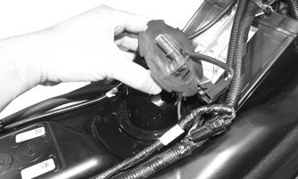
2.Disconnect the fuel pump harness connector; then disconnect the gasline hose from the outlet of the fuel pump by pressing inward on the white connector, pressing in the release, and finally pulling back on the hose. Remove both cable ties secured to the fuel pump ring.
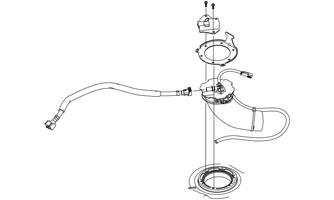
3.Remove and retain the Torx-head screws securing the fuel pump in the fuel tank; then remove the retaining ring. 4.Carefully remove the fuel pump and fuel pickup assembly from the gas tank noting the orientation of the fuel pump outlet for assembling purposes.
WARNING
Since the fuel supply hose may be under pressure, remove it slowly to release the pressure. Place an absorbent towel around the connection to absorb gasoline; then remove the hose slowly to release the pressure. Always wear safety glasses when removing the fuel hoses.
YM-051
NOTE: If the fuel pickup assembly is not being
replaced, inspect the screens for any tears or obstructions. Also check the hoses and replace if necessary.
INSTALLING 1.The two fuel pickups should be pressed together then carefully slide into the fuel pump opening in the gas tank; then install the fuel pump and orientate it so the fuel hose connection faces the front right of the snowmobile.
YM-051
2.Install the retaining ring over the fuel pump and secure the fuel pump to the gas tank assembly using the existing Torx-head screws. Tighten to 40 in.-lb.
3.Connect the fuel pump harness connector to the main harness and secure to the retaining ring with a cable tie; then secure the gasline hose to the fuel pump making sure it locks into place. Secure the cables to the fuel pump ring using two cable ties. 4.Install the fuel pump protector using the existing screws. Tighten to 40 in.-lb. 5.Install the seat(s).
CAUTION
Use care not to over tighten the retaining plate screws or damage to the gas tank may result.
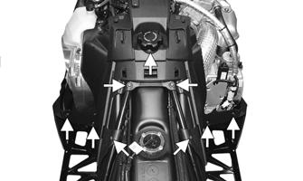
REMOVING 1.Remove the access panels, hood, and the seat. 2.Disconnect the battery; then remove the battery cables from the gas tank. 3.Disconnect the reverse alarm; then remove the machine screws securing the console(s). 4.Remove and retain all four cap screws securing the rear spar tubes to the chassis and steering support. 5.Disconnect the gasline hose, vent hose, and fuel pump harness. Remove the gas tank.
INSTALLING 1.Install the gas tank; then connect the gasline hose, vent hose, and fuel pump harness. 2.Install the rear spar tubes and secure to the chassis and steering support using the four cap screws.
Tighten to 23 ft-lb. 3.Connect the reverse alarm; then use the machine screws to secure the console(s). 4.Position the battery and secure the battery cables to the battery. Tighten securely. 5.Install the lower console; then install the access panels, hood, and seat.