24 minute read
Electrical Systems

All tests of the electrical components should be made using the digital Fluke Model 77 Multimeter. Replace any component that does not have a test value within specifications. NOTE: Whenever using a digital-style tester, “open
(infinite resistance)” denotes an overload and the meter reading will be OL since the meter is not calibrated to register resistance values of that magnitude.
NOTE: Always check the appropriate fuse before
testing a component for failure.
NOTE: Whenever a part is worn excessively,
cracked, or damaged in any way, replacement is necessary.
SPECIAL TOOLS A number of special tools must be available to the technician when servicing the electrical systems. NOTE: When indicated for use, each special tool
will be identified by its specific name, as shown in the chart below, and capitalized.
NOTE: Special tools are available from the Arctic
Cat Service Parts Department.
Description p/n
CATT II 0544-023 Arctic Cat Diagnostic System Manual 2256-974 Laptop Diagnostic Tool 0744-048 Actuator Test Harness 0644-518 Fluke Model 77 Multimeter 0644-559 MaxiClips 0744-041 Throttle Position Sensor (TPS) Adjustment Tool Kit 3639-891
Ignition System
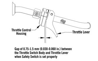
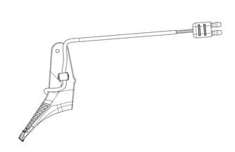
NOTE: There must be 0.030-0.060 in. free-play
between the throttle lever and the control housing.
0752-478
TROUBLESHOOTING 1.Remove the spark plugs and visually check their condition. Replace any fouled plug. Attach the spark plugs to the high tension leads and ground them to the engine.
CAUTION
Do not ground the spark plug on the cylinder head cover. The cover is made of magnesium and any contact with spark or electrical arc will severely pit the surface. CAUTION
Before checking for spark, place all the engine switches in the deactivated position. In the event the engine could be flooded, engage the starter several times to clear the engine of excess fuel.
CAUTION
Never crank the engine over without grounding the spark plugs. Damage to coils and/or CDI/ECM may result.
NOTE: Make sure the ignition switch and the emer-
gency stop switch are in the ON position.
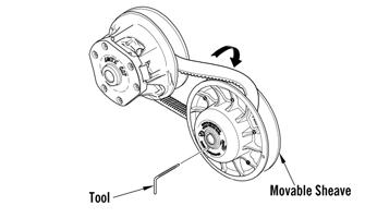
2.Crank the engine over and check for spark. If no spark is present, check to make sure the throttle cable is properly tensioned. Compress the throttle control and while holding the throttle control in this position, crank the engine over and check for spark. If spark is now present, adjust the throttle cable tension.
TESTING Throttle Control Switch 1.Disconnect the handlebar harness connector; then connect the red meter lead to the yellow wire; then connect the black meter lead to the black wire.
2.With the throttle lever in the idle position, the meter must read less than 1 ohm. If the meter reads OL (infinite resistance), replace the control assembly. 3.Move the throttle lever to the wide open position.
The meter must read OL (infinite resistance). If the meter reads less than 1000 ohms, replace the control assembly.
Throttle Position Sensor
VERIFYING TPS ADJUSTMENT TOOL Before using the TPS adjustment tool, verify its battery condition. The battery used in the tool is a 9-volt battery. To check battery condition, use a digital volt/ohmmeter set on DC volt scale. Test between the adjustment tool black and red jacks. Insert the red lead of the digital voltmeter into the red jack of the adjustment tool and the black lead of the digital voltmeter into the black jack of the adjustment tool. The green power light of the analyzer should now be illuminated. If voltage is found below 4.9 volts, replace the battery. NOTE: The Test Harness must be plugged into the
analyzer for testing voltage. Always verify battery voltage is at least 4.9 DC volts before testing TPS.
Component data can be retrieved using the CATT II. Utilize the Sensor Data screen.
Component data can be retrieved using the CATT II. Utilize the Sensor Data screen.
NOTE: If the snowmobile is in warranty, breaking
the seal on the idle screw jam nut or the Phillips-head screws on the TPS will void warranty. If the TPS is tested out of specification, the throttle body must be replaced. If the snowmobile is out of warranty, proceed to Adjusting TPS.
NOTE: The TPS should be checked using the CATT
II Tool.
ADJUSTING TPS
NOTE: Adjusting the TPS is for out of warranty
snowmobiles only.
NOTE: The throttle shaft must be against the throt-
tle stop for this procedure.
CAUTION
Never adjust the throttle plate stop screw and nut. The idle circuit is controlled by the ISC valve.
NOTE: Adjusting the TPS is for out of warranty
snowmobiles only.
NOTE: The TPS should be adjusted using the CATT
II Tool.
REPLACING TPS NOTE: Replacing the TPS is for out of warranty
snowmobiles only.
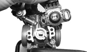
Removing 1.Remove the access panels, hood, air intake assembly. 2.Disconnect TPS wiring harness from the TPS; then noting the TPS position, remove the screws and washers securing TPS to the throttle body housing and remove the sensor.
Installing 1.Install the new TPS onto the throttle shaft by aligning the “flats” on the throttle shaft cam with the alignment points of the sensor; then rotate the sensor until properly positioned on the throttle body.
YM-067
2.Install the screws w/ washers securing the sensor to the throttle body. Do not tighten at this time. 3.Adjust the TPS using the CATT II Tool. NOTE: Before installing the TPS harness connector,
apply dielectric grease to the connector pins.
Electrical Resistance Tests
NOTE: Replace any component that does not have a
test value within specifications. If the component tests satisfactorily but is suspected to be faulty, connect the red meter lead to a component lead and the black meter lead to ground. Check for continuity between the component and ground. If continuity is observed, replace the component.
NOTE: The following test should be made using
MaxiClips and the Fluke Model 77 Multimeter set to OHMS scale.
CAUTION
Always disconnect the battery when performing resistance tests to avoid damaging the multimeter.
Magneto Coil 1.Disconnect the three-white-wire connector.
2.Connect the red meter lead to one white wire; then connect the black meter lead to another white wire (a total of three tests). 3.Resistance must be 0.15-0.23 ohm.
Crankshaft Position Sensor 1.Disconnect the sensor.
2.Connect the red meter lead to the gray wire; then connect the black meter lead to the black wire.
3.Resistance must be 336-504 ohms.
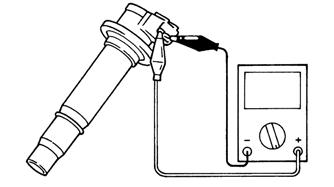
Ignition Coil 1.Disconnect an ignition coil connector. 2.Connect the red meter lead to one terminal; then connect the black meter lead to the other terminal. Primary coil resistance must be 1.19-1.61 ohms.
SNO-655
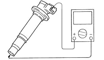
3.Connect the red meter lead to one of the terminals; then connect the black meter lead to the bottom of the coil. Secondary coil resistance must be 8.5k-11.5k ohms.
SNO-656
4.Repeat the test on the other two ignition coils. NOTE: If resistance is not within specification, the
coil must be replaced.
Injection Coil (1) 1.Test between the red/blue and the red/black wires from the injection coil. 2.Resistance must be 86.4-105.6 ohms.
Injection Coil (2) 1.Test between the red/blue and the green/black wires from the injection coil. 2.Resistance must be 86.4-105.6 ohms.
Injection Coil (3) 1.Test between the red/blue and the blue/black wires from the injection coil. 2.Resistance must be 86.4-105.6 ohms.
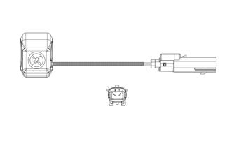
Fuel Injector 1.Disconnect the fuel injector wiring harness. 2.Test between the two injector terminals. Resistance must be 86.4-105.6 ohms.
Coolant Temperature Sensor 1.Disconnect the coolant temperature sensor wiring harness from the main harness.
Air Temperature Sensor NOTE: The component temperature must be
known before conducting this test. Allow the engine to reach room temperature.
1.Disconnect the wiring harness from the air temperature sensor.
2.Set the meter selector in the OHMS position and test the sensor connector. Compare with the Voltage/Resistance Chart - Air Temperature in this section.
NOTE: The air temperature sensor utilizes a therm-
istor. Resistance will change as temperature varies.
Voltage Regulator Tests
NOTE: The following test should be made using
MaxiClips and the Fluke Model 77 Multimeter set to DC Volt scale.
This test should be made at the three-pin connector of the regulator/rectifier.
! WARNING
Most voltages generated by the ignition system are sufficient to interrupt pacemakers! All technicians, especially those using pacemakers, must avoid contact with all electrical connections after the engine has been started.
NOTE: Test the connector that comes from the
engine.
1.Set the meter selector to the DC Voltage position. 2.Connect the red tester lead to the positive battery post; then connect the black tester lead to the negative battery post. 3.With the engine running at 2500-3000 RPM, the meter must show 12-14.5 DC volts.
4.Set the meter selector to the AC Voltage position. 5.Test between the three yellow wires for a total of three tests.
6.With the engine running at 2500-3000 RPM, all wire tests must be within 36-44 volts.
NOTE: If tests failed, check all connections, etc.,
and test again. If no voltage is present, replace the stator assembly.
Testing Fuel Gauge Sender
NOTE: Before testing the sender, verify the harness
from the sender to the gauge is satisfactory.
1.Remove the seat.
2.Disconnect the fuel gauge sender unit from the main wiring harness; then connect the ohmmeter leads to the two black sender wires.
3.Compare the reading to the chart following.
Full <20 ohms 1/2 40-56 ohms Empty 76-105 ohms
Emergency Stop Switch
RESISTANCE 1.Disconnect the stop switch connector; then set the selector to the OHMS position. 2.Connect one tester lead to one pin; then connect the other tester lead to the other pin.
ONS-118
3.With the switch in the OFF position, the meter must read OL (infinite resistance). 4.With the switch in the ON position, the meter must read less than 1 ohm resistance.
Starter Relay Solenoid
TESTING NOTE: The electric start solenoid may be tested
using either one of the following methods.
Method #1 1.Disconnect the solenoid connector from the main wiring harness. 2.Place the ohmmeter leads across the solenoid coil terminals. The ohmmeter must read 3-5 ohms.
NOTE: An in-line ammeter would measure between
2 and 4 amps of solenoid coil current flow with the battery connected.
CAUTION
NEVER connect an in-line ammeter with the large starter cables because the 200 amps of current flow will instantly damage most ammeters.
Method #2 1.Using the multimeter set to the DC Voltage position, check the relay as follows. 2.Connect the red tester lead to the positive battery terminal; then connect the black tester lead to the starter cable connection on the starter relay. The meter must show battery voltage. NOTE: Engage the brake lever lock and place the
emergency stop switch in the RUN position.
3.Engage the starter while observing the multimeter.
The multimeter should drop to 0 volts and a “click” should be heard from the relay. NOTE: If a “click” is heard and more than 1 volt is
indicated by the multimeter, replace the starter relay. If no “click” is heard and the multimeter continues to indicate battery voltage, proceed to step 4.
4.Disconnect the two-wire plug from the starter relay; then connect the red tester lead to the green wire and the black tester lead to the black wire.
5.Depress the starter button and observe the multimeter.
NOTE: If battery voltage is indicated, replace the
starter relay. If no voltage is indicated, check fuse or relay.
Fuse
TESTING 1.Remove the fuse from the fuse holder.
2.Connect the ohmmeter across the fuse end-caps. 3.The ohmmeter must read less than 1 ohm of resistance.
Ignition Switch
TESTING
CAUTION
To prevent ohmmeter damage when testing circuits on snowmobiles equipped with an electric start, be sure to disconnect the battery before testing.
1.Disconnect the wiring harness from the ignition switch; then remove the switch from the console. 2.Using the ohmmeter, test the connections indicated in the following chart. If the meter reads more than one ohm of resistance between connected terminals or less than 1 ohm of resistance on non-connected terminals, the switch must be replaced.
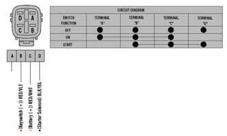
746-246B
NOTE: If the ignition switch tests good, verify bat-
tery voltage to the harness side of the switch plug-in. If there is no voltage, troubleshoot the battery, switch fuse, or starter relay solenoid.
If battery voltage is present at the plug-in and the starter fails to activate, use the following procedure: 1.With the ignition switch plugged in, place the emergency stop switch to the OFF position. 2.Connect the red tester lead to the black/yellow wire; then connect the black tester lead to a suitable ground. 3.Rotate the key to the START position and verify battery voltage. NOTE: If no battery voltage is present, troubleshoot
the harness and/or the starter relay solenoid.
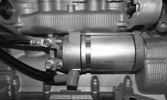
Starter Motor
REMOVING 1.Remove the access panels, hood and the seat. 2.Remove the drive clutch, drive belt, driven clutch, gas tank, and air intake assembly; then remove the two cap screws and nuts securing the rear of the engine to the chassis. 3.Carefully pry the engine enough to remove the starter motor and battery cables from the engine.
YM-060
CLEANING AND INSPECTING 1.Thoroughly clean all components except the armature and brushes in parts-cleaning solvent; then dry with compressed air.
2.Inspect all threaded areas for damaged or stripped threads.
3.Inspect the brush holder assembly and brushes for damage or wear. Using a caliper, measure the length of the brushes. If brush measurement is less than 0.40 in., replace with new brushes and brush springs as a set. 4.Inspect brush leads for cracks, wear, or fraying. If any of these conditions exist, replace with new brushes along with new brush springs as a set. 5.Inspect the rear cover bushing for wear. 6.Inspect the front cover bearing for wear. 7.Inspect the brass commutator end of the armature for any discolored spots or damage. If the commutator is slightly discolored or damaged, the armature must be replaced. This is a molded commutator and no attempt to turn it down in a lathe should be attempted.
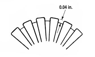
8.Inspect the commutator end of the armature for buildup in the grooves. Carefully remove any buildup by undercutting using a thinly ground hacksaw blade. Do not cut any deeper than the original groove which can be seen by looking at the end of the commutator.
9.Using a caliper, measure the undercut. Maximum undercut groove must be as shown.
CAUTION
Do not wash the armature and brushes in any kind of solvent. Use only compressed air and clean dry, lint-free cloth in cleaning these components.
CAUTION
Do not use emery cloth to clean the commutator as emery particles will become embedded in the brass commutator resulting in a short circuit. Use only #200 grit sandpaper.
SNO-382A
CAUTION
Buildup in the grooves must be removed to prevent any chance of an electrical arc between individual sections of the commutator.
10.Inspect the commutator for shorting using a multimeter and the following procedure:
A.Set the selector to the OHMS position.
B.Touch the black lead to the armature shaft.
C.Using the red tester lead, probe the commutator end of the armature. The meter indicator should not change. If the indicator shows resistance, the armature is shorted and must be replaced. 11.Inspect the armature for shorting using a “growler” and the following procedure:
A.Place the armature in the “growler.”
B.While holding a metal strip on the armature, rotate the armature an entire revolution. If the metal strip vibrates at any point on the armature, the armature is shorted and must be replaced.
0725-653
12.Inspect the ground brushes to make sure they are properly grounded. Use a multimeter and the following procedure:
A.Set the selector to the OHMS position.
B.Touch the black tester lead to a ground brush.
C.Touch the red tester lead to the brush holder assembly. NOTE: If no resistance is indicated, check the
ground connection for tightness and for cleanliness. If there is still no meter indication, replace the brush assembly.
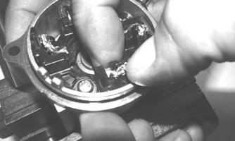
ASSEMBLING 1.With the brush assembly secured in a vise, compress each brush all the way into the housing; then carefully push the brush wire over and down to secure the brush in the fully compressed position.
ZJ143
NOTE: The brushes must be fully compressed to
allow enough room to install the armature.
2.Install the armature into the brush assembly; then using a small needle-nose pliers, carefully move the brush wires upward allowing the brushes to fully contact the commutator.
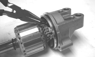
ZJ145
NOTE: After completing step 2, ensure that the
brushes are properly seated to the commutator.
3.Noting the alignment marks made in disassembling, install the magnet housing; then with the magnet housing properly seated to the brush assembly, install the snap ring, shim, and locking plate to the armature shaft. NOTE: If alignment marks were not made during
disassembling, align properly by matching notch on the magnet housing to notch on the brush assembly.
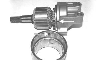
ZJ153A
4.With a suitable driving tool, install new seal into the bearing housing; then install the bearing housing.
NOTE: Prior to installing the bearing housing, position the locking plate with the tabs (A) of the locking plate aligned with the cap screw ears (B) of the starter motor.
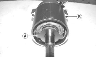
ZJ144A
5.Install the two long cap screws securing the starter motor together; then tighten the cap screws to 108 in.-lb.
ZJ140A
INSTALLING 1.Install the starter motor into the engine; then with the negative battery cable positioned to the top mounting hole, install the two cap screws (threads coated with blue Loctite #243) and tighten to 19 ft-lb. 2.Install the positive cable to the starter motor and tighten securely. Secure the positive and negative cables with cable ties as noted during disassembling.
YM-060
3.Secure the rear of the engine to the chassis using the existing cap screws and nuts Tighten to 93 ft-lb. 4.Install the air intake assembly, drive clutch, drive belt, driven clutch, gas tank, hood and access panels. 5.Install the positive cable to the battery; then install the seat.
Troubleshooting Electric Start
Problem: Hot or Smoking Wires Condition Remedy
1. System wired incorrectly 1.Check wiring against wiring diagram
Problem: Starter Does Not Turn Over Condition Remedy
1. Battery discharged 1.Check/charge the battery 2. Connection loose 2.Check tightness of all connections 3. Grounding improper 3.Check ground connections 4. Fuse blown — not installed 4.Check — replace fuse
Magneto
REMOVING NOTE: Prior to removing the magneto, the engine
oil and cooling system must be drained.
1.Remove the cap screws, nuts, and springs securing the resonator.
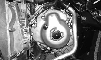
2.Remove the cap screws and nuts securing the
MAG-side chassis support; then remove all clamps and hoses to gain access to the magneto cover.
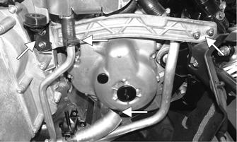
YM-055A
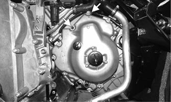
3.Remove the screws securing the magneto cover to the engine; then remove the cover and account for two dowel pins and the gasket. Disconnect the stator from the voltage regulator. NOTE: Note the location of the black screw and
retaining clip as they must be installed in the same location as which they were removed.
YM-056A
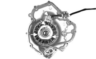
4.Remove the cap screws securing the harness clamp to the magneto cover. Remove the three cap screws securing the magneto to the cover; then remove the magneto assembly.
YM-057A
INSTALLING 1.Place the magneto into position on the cover; then install and tighten the three cap screws (threads coated with blue Loctite #243) to 7.2 ft-lb. With the harness routed properly, install the timing sensor and harness clamp and tighten (threads coated with blue
Loctite #243) to 7.2 ft-lb.
YM-057A
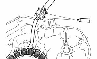
NOTE: Be sure to apply a small amount of sealant
to the grommet before pressing it into the cover.
SNO-380
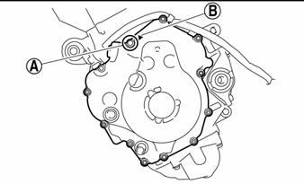
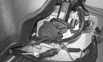
2.Install the two alignment pins in the engine for the magneto cover; then with a new gasket, install the cover and with a crisscross pattern, tighten the screws to 8.7 ft-lb.
YM-056
NOTE: The black screw (A) indicated by the black
arrow (B) must have blue Loctite #243 applied to the threads. Tighten to 8.7 ft-lb.
SNO-381A
3.Secure all coolant hoses and oil hoses using the existing clamps; then secure the left-side support using the existing cap screws and nuts. Tighten securely.
YM-055A
4.Install the resonator and secure using existing hardware.
NOTE: At this point, fill and bleed the oil and cool-
ing systems.
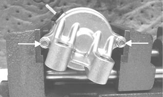
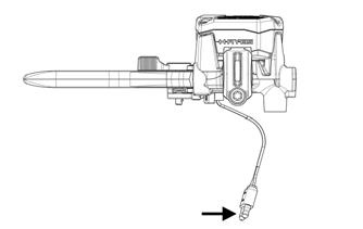
Brake Light Switch
TESTING/REMOVING 1.Disconnect the brake light switch gray and brown two-wire connector (located near the brake lever). 2.To test the brake light switch, connect one tester lead to the brown terminal; then connect the other lead to the gray terminal.
ONS-116
3.With the brake lever compressed, the meter must read 1 ohm or less resistance. With the brake lever released, the meter must read OL (open). If the meter does not read as specified, the brake light switch is defective and must be replaced. 4.To remove the switch, pry the brake switch from the brake assembly.
ONS-117
INSTALLING 1.Press the switch into the brake assembly making sure it is fully seated. 2.Connect the switch harness to the main wiring harness. Position the wires so they will not be either pinched or come in contact with any moving components. Cable tie as needed. Start the engine and check the switch for proper operation.
Testing Headlight Dimmer Switch
1.With the key off, open the hood; then disconnect the 12-pin handlebar connector from the main harness. 2.Read continuity between the red/yellow and the blue wires for the high beam (red/yellow to white should be open circuit). 3.Read continuity between the red/yellow and the white wires for the low beam (red/yellow to blue should be open circuit). 4.The voltage check can read 12-15 VDC feeding the control, red/yellow to black, On high beam, 12-15
VDC blue (+) to black (-), and on low beam, 12-15
VDC white (+) to black (-).
Testing Handlebar Warmer Elements
NOTE: Resistance will vary due to temperature;
therefore, this test should be made at room temperature of 20° C (68° F).
NOTE: To access the element connectors, the han-
dlebar control assembly for the side being tested must be removed.
1.Disconnect the handlebar warmer three-wire connector.
2.In the element connector, connect one ohmmeter lead to the green/white lead; then connect the other ohmmeter lead to the green lead. 3.The meter must read between 12.6-15.4 ohms.
4.In the element connector, connect the ohmmeter between the green/blue and green lead wires. 5.The meter must read between 6.3-7.7 ohms.
6.Replace any element measuring less than or more than the specified amount. NOTE: Repeat test for the other element. 7.Connect the leads; then install the handlebar control assembly and secure the handlebar pad (if applicable).
Testing Thumb Warmer Element
NOTE: Resistance will vary due to temperature;
therefore, this test should be made at room temperature of 20° C (68° F).
1.Disconnect the thumb warmer two-wire connector.
ONS-120
2.Connect one ohmmeter lead to the one lead; then connect the other ohmmeter lead to the other lead.
3.The meter must read 40 (±4) ohms.
Testing Handlebar Warmer/Thumb Warmer Switch
NOTE: The switch should only be checked using the
CATT II Tool. Instructions will be included with the tool.
Testing Tether
1.Disconnect the two-wire connector from the tether switch. 2.Connect one ohmmeter lead to one pin; then connect the other ohmmeter lead to the other pin. 3.With the tether cord installed on the switch, the meter must read less than 1 ohm of resistance. With the tether cord removed from the switch, the meter must read OL (infinite resistance).
Testing Passenger Handwarmer Switch
1.Disconnect the lead wires from the switch.
2.With the switch in the LO position, connect one ohmmeter lead to the green/white wire at the connector; then connect the other ohmmeter lead to the red/black wire at the connector. The meter must read less than 1 ohm of resistance.
3.With the switch in the HI position, connect one ohmmeter lead to the green/blue wire at the connector; then connect the other ohmmeter lead to the red/black wire at the connector. The meter must read less than 1 ohm of resistance.
Testing Passenger Handwarmer Elements
NOTE: During this test, resistance will vary due to
temperature; therefore, this test should be made at room temperature of 20° C (68° F).
1.Disconnect the lead wires from the main wiring harness.
2.For the LO position, connect one ohmmeter lead to the green/white wire from the element; then connect the other ohmmeter lead to the green wire from the element. The meter must read between 18.9-23.1 ohms.
3.For the HI position, connect one ohmmeter lead to the green/blue wire from the element; then connect the other ohmmeter lead to the green wire from the element. The meter must read between 9.5-11.5 ohms.
Testing Seat Heater Switches
NOTE: The seat heater elements cannot be tested.
OPERATOR HEATER SWITCH - Resistance NOTE: The element connectors are located at the
rear of the front seat beneath the flap.
1.Disconnect the main harness/element connector.
2.Connect one ohmmeter lead to the red/black main harness wire; then connect the other ohmmeter lead to the green/red main harness wire. The meter must read the following ± 5%:
LO 4.32K ohms HI 3.75K ohms
LO 4.32K ohms HI 3.75K ohms
NOTE: If resistance is not within specification, trou-
bleshoot the switch connector located below the steering support. If the switch connector tests good, replace the switch.
PASSENGER HEATER SWITCH - Resistance 1.Disconnect the main harness/element connector.
2.Connect one ohmmeter lead to the red/black main harness wire; then connect the other ohmmeter lead to the green/red main harness wire. The meter must read the following ± 5%:
NOTE: If resistance is not within specification, trou-
bleshoot the switch connector located beneath the seat. If the switch connector tests good, replace the switch.
OPERATOR/PASSENGER SWITCH - Voltage 1.Disconnect the main harness/element connector.
NOTE: For this procedure, test the main harness
side of the connector, not the element side of the connector.
2.Connect one meter lead to the red/black main harness wire; then connect the other meter lead to the black main harness wire.
3.Start the engine. The meter must read 12-15 volts. NOTE: If this voltage test does not read within spec-
ification, troubleshoot the main harness, F-2 fuse, K-2 relay, or the F-7 main fuse.
Testing Speedometer Sensor
NOTE: The following test should be made using
MaxiClips and the Fluke Model 77 Multimeter set to the DC Volt scale.
NOTE: Prior to testing the sensor, inspect the
three-wire connector on the sensor harness for contamination, broken pins, and/or corrosion. With the engine running, note that a power supply of 10.8-14.4 DC volts exists at the main harness/speedometer connector.
PC067B
1.Elevate the rear of the snowmobile onto a suitable safety stand. 2.Set the meter selector to the DC Voltage position. 3.At the sensor side of the plug-in, connect the red maxiclip and meter lead to the white/orange lead; then connect the black maxiclip and meter lead to the black lead.
4.Connect a positive 12-volt DC power supply to the red/blue wire; then connect a negative cable to the black wire from the main harness side of the plug-in. 5.Rotate the driven clutch. The meter must read 0 volts and 12 volts alternately.
Testing Gear Position Switch
1.Disconnect the switch two-wire connector.
2.Connect one ohmmeter lead to one black wire; then connect the other ohmmeter lead to the other black wire.
3.With the reverse button pressed in, the meter must read less than 1 ohm of resistance. With the reverse button released, the meter must read OL (infinite resistance). NOTE: If the meter does not read as specified in
either test, the switch is defective and must be replaced.
Testing Shift Switch
NOTE: The switch should only be checked using the
CATT II Tool. Instructions will be included with the tool.
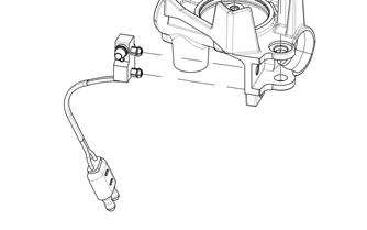
Testing Shift Actuator
NOTE: The actuator is located on the chain case. 1.Disconnect the actuator two-wire connector; then connect Actuator Test Harness onto the harness side of the connector.
2.Connect one meter lead to the red/blue lead of the test harness; then connect the other meter lead to the yellow/orange wire lead of the test harness. 3.Press the reverse button; there should be a flash of
DC battery voltage indicated on the meter. Release the reverse button; then again press the reverse button; there should be a flash of DC battery voltage indicated on the meter.
NOTE: If the meter indicates a flash of voltage but
the actuator does not function, the actuator is defective and must be replaced.
NOTE: If the meter does not indicate a flash of volt-
age, troubleshoot the main harness.
Testing Heated Shield Outlet
NOTE: The outlet is located on the upper console. 1.Connect one meter lead to the center of the plug; then connect the other meter lead to the outside ring of the outlet.
2.With the engine running, the meter should show the system voltage.