52 minute read
Engine/Transmission

This section has been organized into sub-sections which show a progression for the complete servicing of the ATV engine/transmission. To service the center crankcase halves, the engine/transmission must be removed from the frame.
To service top-side, left-side, and right-side components, the engine/transmission does not have to be removed from the frame.
NOTE: The manufacturer recommends the use of
new gaskets, lock nuts, and seals and lubricating all internal components when servicing the engine/transmission.
NOTE: A new ATV and an overhauled ATV engine
require a “break-in” period. The first 10 hours (or 200 miles) are most critical to the life of this ATV. Proper operation during this break-in period will help ensure maximum life and performance from the ATV. Instruct the customer to follow the proper break-in procedure as described in the Operator’s Manual.
SPECIAL TOOLS A number of special tools must be available to the technician when performing service procedures in this section. Refer to the current Special Tools Catalog for the appropriate tool description. NOTE: When indicated for use, each special tool
will be identified by its specific name, as shown in the chart below, and capitalized.
NOTE: Special tools are available from the Textron
Off Road Service Parts Department.
Description p/n
Crankcase Separator/Crankshaft Remover 0444-152 Piston Pin Puller 0644-328 Spanner Wrench 0444-192 Flywheel Holder 0444-193 Magneto Rotor Remover 0444-187 Tappet Adjuster 0444-189 Surface Plate 0644-016 Driven Pulley Compressor 0444-195 V Blocks 0644-535
Troubleshooting
Problem: Engine will not start or is hard to start (Compression too low) Condition Remedy
1. Valve clearance out of adjustment 2. Valve guides worn — seated poorly 3. Valves mistimed 4. Piston rings worn excessively 5. Cylinder bore worn 6. Spark plug seating poorly 7. Starter motor cranks too slowly — does not turn 1.Adjust clearance 2.Repair — replace guides 3.Adjust valve timing 4.Replace rings 5.Replace cylinder 6.Tighten plug 7.See Electrical System
Problem: Engine will not start or is hard to start (No spark) Condition Remedy
1. Spark plug fouled 2. Spark plug wet 3. Magneto defective 4. CDI unit defective 5. Ignition coil defective 6. High-tension lead open — shorted
1.Clean — replace plug 2.Clean — dry plug 3.Replace magneto 4.Replace CDI unit 5.Replace ignition coil 6.Replace high tension lead
Problem: Engine will not start or is hard to start (No fuel reaching the carburetor) Condition Remedy
1. Gas tank cap obstructed 2. Carburetor inlet needle defective 3. Fuel hose obstructed 4. Fuel screens obstructed 1.Clean or replace cap 2.Replace needle 3.Clean — replace hose 4.Clean — replace inlet screen — valve screen
Problem: Engine stalls easily Condition Remedy
1. Spark plug fouled 2. Magneto defective 3. CDI unit defective 4. Carburetor jets obstructed 5. Valve clearance out of adjustment 1.Clean plug 2.Replace magneto 3.Replace CDI unit 4.Clean jets 5.Adjust clearance
Problem: Engine noisy (Excessive valve chatter) Condition Remedy
1. Valve clearance too large 2. Valve spring(s) weak — broken 3. Rocker arm — rocker arm shaft worn 4. Camshaft worn 1.Adjust clearance 2.Replace spring(s) 3.Replace arm — shaft 4.Replace camshaft
Problem: Engine noisy (Noise seems to come from piston) Condition Remedy
1. Piston — cylinder worn 2. Combustion chamber carbon buildup 3. Piston pin — piston pin bore worn 4. Piston rings — ring groove(s) worn
1.Replace — service piston — cylinder 2.Clean chamber 3.Replace — service pin — bore 4.Replace rings — piston
Problem: Engine noisy (Noise seems to come from timing chain) Condition Remedy
1. Chain stretched 2. Sprockets worn 3. Tension adjuster malfunctioning
1.Replace chain 2.Replace sprockets 3.Repair — replace adjuster
Problem: Engine noisy (Noise seems to come from crankshaft) Condition Remedy
1. Bearing worn — burned 2. Lower rod-end bearing worn — burned 3. Connecting rod side clearance too large
1.Replace bearing 2.Replace bearing 3.Replace thrust washer(s)
Problem: Engine noisy (Noise seems to come from transmission) Condition Remedy
1. Gears worn — rubbing 2. Splines worn 3. Primary gears worn — rubbing 4. Bearings worn 5. Bushing worn
1.Replace gears 2.Replace shaft(s) 3.Replace gears 4.Replace bearings 5.Replace bushing
Problem: Engine noisy (Noise seems to come from secondary-transmission/right-side cover) Condition Remedy
1. Gears — shaft(s) worn 2. Bearing(s)/bushing(s) damaged 1.Replace gears — shafts 2.Replace bearing(s)/bushing(s)
Problem: Engine noisy (Noise seems to come from secondary bevel gear and final driven shaft) Condition Remedy
1. Drive — driven bevel gears damaged — worn 2. Backlash excessive 3. Tooth contact improper 4. Bearing damaged 5. Gears worn — rubbing 6. Splines worn 7. Final driven shaft thrust clearance too large 1.Replace gears 2.Adjust backlash 3.Adjust contact 4.Replace bearing 5.Replace gears 6.Replace shaft(s) 7.Replace thrust washer(s)
Problem: Centrifugal clutch slipping Condition Remedy
1. Clutch shoes worn 2. Clutch housing excessively worn 3. Drive belt slipping — worn
1.Replace shoes 2.Replace clutch housing 3.Replace drive belt
Problem: Secondary-transmission will not shift or shift back Condition Remedy
1. Sliding dog broken — worn 2. Gearshift fork broken — worn 3. Hi/Low shift lever out of adjustment 4. Gearshift cam worn 5. Cam stopper spring weak 6. Gearshift fork shaft worn 7. Engine idle too high 8. Shift linkage out of adjustment 1.Replace dog 2.Replace fork 3.Adjust lever 4.Replace cam 5.Replace spring 6.Replace shaft 7.Adjust engine idle 8.Adjust shift linkage
Problem: Engine idles poorly Condition Remedy
1. Valve clearance out of adjustment 2. Valve seating poor 3. Valve guides defective 4. Rocker arms — arm shaft worn 5. Magneto defective 6. CDI unit defective 7. Spark plug fouled — gap too wide 8. Ignition coil defective 9. Float out of adjustment 10. Jets obstructed 11. Pilot screw setting improper
1.Adjust clearance 2.Replace — service seats — valves 3.Replace guides 4.Replace arms — shafts 5.Replace magneto 6.Replace CDI unit 7.Adjust gap — replace plug 8.Replace ignition coil 9.Adjust float height 10.Clean jets 11.Adjust pilot screw
Problem: Engine runs poorly at high speed Condition Remedy
1. High RPM “cut out” against RPM limiter 2. Valve springs weak 3. Valve timing out of adjustment 4. Cams — rocker arms worn 5. Spark plug gap too narrow 6. Ignition coil defective 7. Float level too low 8. Air cleaner element obstructed 9. Fuel hose obstructed 1.Shift into higher gear — decrease speed 2.Replace springs 3.Adjust timing 4.Replace cams — arms 5.Adjust gap 6.Replace ignition oil 7.Adjust float height 8.Clean element 9.Clean — prime hose
Problem: Exhaust smoke dirty or heavy Condition Remedy
1. Oil (in the engine) overfilled — contaminated 2. Piston rings — cylinder worn 3. Valve guides worn 4. Cylinder wall scored — scuffed 5. Valve stems worn 6. Stem seals defective 7. Air cleaner element obstructed 8. Float level too high 1.Drain excess oil — replace oil 2.Replace — service rings — cylinder 3.Replace guides 4.Replace — service cylinder 5.Replace valves 6.Replace seals 7.Clean element 8.Adjust float level
Problem: Engine lacks power Condition Remedy
1. Valve clearance incorrect 2. Valve springs weak 3. Valve timing out of adjustment 4. Piston ring(s) — cylinder worn 5. Valve seating poor 6. Spark plug fouled 7. Rocker arms — shafts worn 8. Spark plug gap incorrect 9. Carburetor jets obstructed 10. Float level out of adjustment 11. Air cleaner element obstructed 12. Oil (in the engine) overfilled — contaminated 13. Intake manifold leaking air 14. Cam chain worn
1.Adjust clearance 2.Replace springs 3.Adjust timing 4.Replace — service rings — cylinder 5.Repair seats 6.Clean — replace plug 7.Replace arms — shafts 8.Adjust gap — replace plug 9.Clean jets 10.Adjust float height 11.Clean element 12.Drain excess oil — change oil 13.Tighten — replace manifold 14.Replace cam chain
Problem: Engine overheats Condition Remedy
1. Carbon deposit (piston crown) excessive 2. Oil low 3. Octane low — gasoline poor 4. Oil pump defective 5. Oil circuit obstructed 6. Gasoline level (in float chamber) too low 7. Intake manifold leaking air 8. Coolant level low 9. Fan malfunctioning 10. Fan switch malfunctioning 11. Thermostat stuck — closed 12. Radiator hoses - cap damaged — obstructed
1.Clean piston 2.Add oil 3.Drain — replace gasoline 4.Replace pump 5.Clean circuit 6.Adjust float height 7.Tighten — replace manifold 8.Fill — examine system for leaks 9.Check fan fuse — replace fan 10.Replace fan switch 11.Replace thermostat 12.Clear obstruction — replace hoses
Removing Engine/ Transmission
Many service procedures can be performed without removing the engine/transmission from the frame. Closely observe the note introducing each sub-section for this important information.
Secure the ATV on a support stand to elevate the wheels.
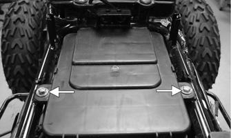
1.Remove the seat.
2.Remove the negative cable from the battery; then remove the positive cable.
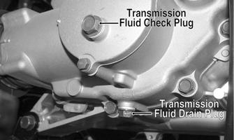
3.Drain the coolant, engine oil, and transmission gear lubricant; then install the drain plugs and tighten to 21 ft-lb. AT THIS POINT
If the technician’s objective is to service/replace left-side cover oil seals, the engine/transmission does not have to be removed from the frame.
! WARNING
Make sure the ATV is solidly supported on the support stand to avoid injury.
KM314C
KM954A
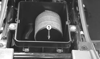
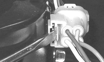
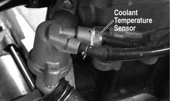
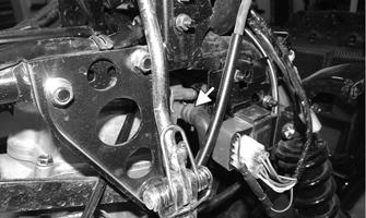
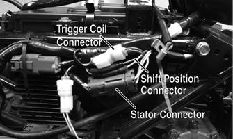
4.Remove the front body panel assembly (see Steering/Body/Controls). 5.Remove the air filter housing and remove the gas tank (see Fuel/Lubrication/Cooling). 6.Remove the muffler assembly (see Steering/Body/Controls). 7.Remove the carburetor (see Fuel/Lubrication/Cooling). 8.Remove the ignition coil (see Electrical System). 9.From the right side of the frame, disconnect the stator connector, gear position connector, trigger coil connector, and coolant temperature sensor.

KM347B
KM324A
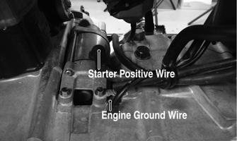
10.Remove the starter positive wire; then remove the engine ground wire from the crankcase.
KM319A
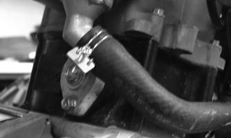
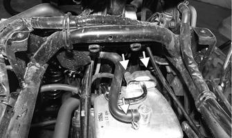
11.Remove the front and rear V-belt cooling boots from the V-belt housing; then remove the coolant hoses from the engine.
KM323
KM314
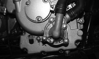
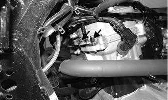
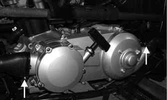
12.Loosen the output drive boot clamp; then slide the boot off the output housing.

KM315A
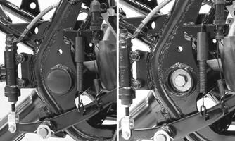
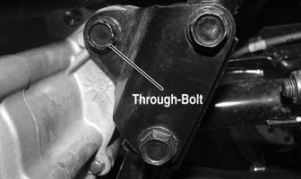
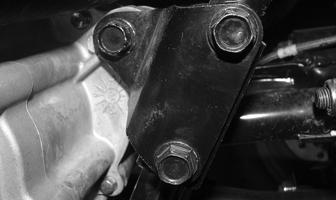
13.Disconnect the shift linkage from the transmission shift arm; then swing the shift linkage forward and out of the way. 14.Remove the front engine through-bolt; then remove the two engine mounting brackets from the frame. 15.Attach a suitable lifting sling and engine lift to the front engine mounting boss; then using an engine lift, apply slight upward pressure on the engine/transmission.

KM332A
16.Remove the upper rear and lower rear engine through-bolts to free the engine/transmission; then raise the front of the engine/transmission sufficiently to allow the engine assembly to be moved forward enough to disengage the driveshaft.
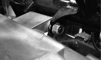
KM333A
KM325A
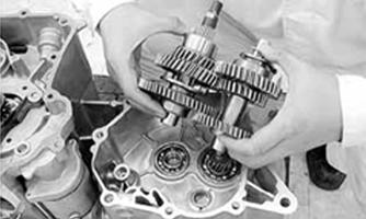
17.Swing the rear of the engine/transmission to the left; then slide the engine out of the left side of the frame.
KM329

KM331
Top-Side Components
NOTE: For efficiency, it is preferable to remove and disassemble only those components which need to be addressed and to service only those components. The technician should use discretion and sound judgment.
NOTE: The engine/transmission does not have to
removed from the frame for this procedure.
AT THIS POINT
To service any one specific component, only limited disassembly of components may be necessary. Note the AT THIS POINT information in each sub-section.
Removing Top-Side Components
A.Valve Cover B.Cylinder Head NOTE: Remove the spark plug and timing inspec-
tion plug; then rotate the crankshaft to top-dead-center of the compression stroke.
1.On the right side, remove the air intake hose from the cylinder head cover. Retain the hose clamp.
KM941A
2.Remove the vent hose from the top of the cylinder head cover. Retain the hose clamp. 3.Remove the cap screws and nuts securing the air pipe to the cylinder head cover.
KM937A
KM939A
4.Remove the cap screws securing the cylinder head cover. Account for the O-ring.
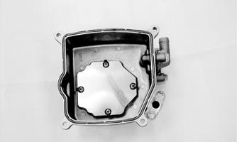
NOTE: Keep the mounting hardware with the cover
for assembly purposes.
5.Remove the plug from the cam chain tensioner; then turn the cam chain tensioner screw clockwise to release the chain tension.
KM704A
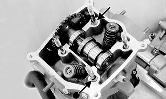
6.Using a crisscross pattern, loosen the four nuts securing the camshaft holder to the cylinder head. Use 2-3 steps until the nuts are all free; then remove the camshaft holder. Account for four washers and two alignment pins.

KM706A
KM707A
7.Remove the camshaft gear from the cam chain; then secure the timing chain so it will not fall into the engine. Remove the camshaft. 8.Remove the two external cap screws securing the cylinder head to the cylinder; then remove the cylinder head. Account for two alignment pins and a cylinder head gasket.
KM718A
9.Remove the cam chain guide; then disconnect the coolant hose and remove the cylinder. Support the piston with rubber bands or other suitable supports.
Account for two dowel pins and the cylinder gasket.
KM450
AT THIS POINT
To service valves and cylinder head, see Servicing Top-Side Components sub-section.
AT THIS POINT
To inspect cam chain guide, see Servicing Top-Side Components sub-section.
C.Cylinder D.Piston NOTE: Steps 1-6 in the preceding sub-section must
precede this procedure.
AT THIS POINT
To service cylinder, see Servicing Top-Side Components sub-section.
CAUTION
When removing the cylinder, be sure to support the piston to prevent damage to the crankcase and piston.
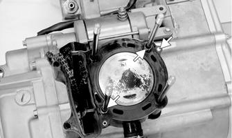
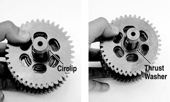
10.Using a needle nose pliers, remove one piston pin circlip. Take care not to drop it into the crankcase.
KM451
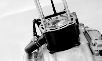
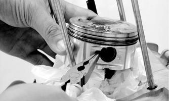
11.Using Piston Pin Puller, remove the piston pin.
Account for the opposite-side circlip. Remove the piston. NOTE: It is advisable to remove the opposite-side
circlip prior to using the puller.
NOTE: Support the connecting rod with rubber
bands to avoid damaging the rod or install a connecting rod holder.
NOTE: If the existing rings will not be replaced with
new rings, note the location of each ring for proper installation. When replacing with new rings, replace as a complete set only. If the piston rings must be removed, remove them in this sequence.
CAUTION
Do not allow the connecting rod to go down inside the crankcase. If the rod is down inside the crankcase and the crankshaft is rotated, severe damage will result.
A.Starting with the top ring, slide one end of the ring out of the ring-groove. B.Remove each ring by working it toward the dome of the piston while rotating it out of the groove.
AT THIS POINT
To service piston, see Servicing Top-Side Components sub-section.
AT THIS POINT
To service center crankcase components only, proceed to Removing Left-Side Components.
Servicing Top-Side Components
VALVE ASSEMBLY When servicing valve assembly, inspect valve seats, valve stems, valve faces, and valve stem ends for pits, discoloration, or other signs of abnormal wear. NOTE: Whenever a valve is out of tolerance, it must
be replaced.
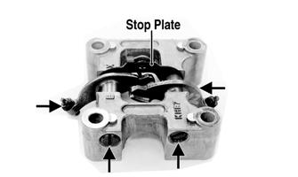
Cleaning/Inspecting Camshaft Holder 1.Remove the rocker arm shafts, rocker arms, and stop plate from the camshaft holder.
KM708A
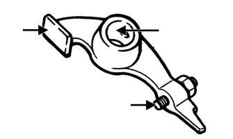
2.Inspect the camshaft holder for cracks, distortion, or galling. 3.Inspect the rocker arm shafts for blue discoloration or scoring. 4.Inspect the rocker arms for excessive wear, loose adjusters, or scored camshaft followers.
KM710A
Removing Valves NOTE: Keep all valves and valve components as a
set. Note the original location of each valve set for use during installation. Return each valve set to its original location during installation.
1.Using a valve spring compressor, compress the valve springs and remove the valve cotters. Account for an upper spring retainer.
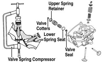
2.Remove the valve seal, valve springs, and the lower remaining spring seat. Discard the valve seal. NOTE: The valve seals must be replaced. 3.Invert the cylinder head and remove the valves.
Measuring Valve Stem/Valve Guide Clearance 1.Using a micrometer, measure the valve stem outside diameter; then using a suitable snap gauge and micrometer, measure the valve guide inside diameter. 2.Acceptable clearance must be within specifications.
Inspecting Valve Face Inspect the valve face for pitting, grooving, or discoloration. Replace any valve that is damaged.
CYLINDER HEAD ASSEMBLY NOTE: If the cylinder head cannot be trued, it must
be replaced.
Cleaning/Inspecting Cylinder Head 1.Using a non-metallic carbon removal tool, remove any carbon build-up from the combustion chamber making sure not to nick, scrape, or damage the combustion chamber or the sealing surface. 2.Inspect the spark plug hole for any damaged threads.
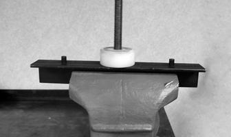
Repair damaged threads using a “heli-coil” insert. 3.Place the cylinder head on the surface plate covered with #400 grit wet-or-dry sandpaper. Using light pressure, move the cylinder head in a figure-eight motion. Inspect the sealing surface for any indication of high spots. A high spot can be noted by a bright metallic finish. Correct any high spots before assembly by continuing to move the cylinder head in a figure-eight motion until a uniform bright metallic finish is attained.
CAUTION
Water or parts-cleaning solvent must be used in conjunction with the wet-or-dry sandpaper or damage to the sealing surface may result.
Measuring Cylinder Head Distortion 1.Remove any carbon buildup in the combustion chamber.
2.Lay a straightedge across the cylinder head; then using a feeler gauge, check the distortion factor between the head and the straightedge. 3.Maximum distortion must not exceed specifications.

CC141D
Measuring Camshaft Lobe Height 1.Using a calipers, measure each cam lobe height.
ATV1013A
2.The lobe heights must not be less than minimum specifications.
Inspecting Camshaft Bearing Journal 1.Inspect the bearing journal for scoring, seizure marks, or pitting. 2.If excessive scoring, seizure marks, or pitting is found, the cylinder head assembly must be replaced.
Measuring Rocker Arm/ Shaft Clearance 1.Using a dial calipers, measure the inside diameter of the rocker arm; then measure the outside diameter of the rocker arm shaft.
2.Acceptable clearance must not exceed specifications.
Installing Valves 1.Apply grease to the inside surface of the valve seals; then place a lower spring seat and valve guide seal over each valve guide. 2.Insert each valve into its original valve location. 3.Install the valve springs with the closest coils toward the cylinder head.

ATV-1011A
4.Place a spring retainer over the valve springs; then using the valve spring compressor, compress the valve springs and install the valve cotters.
KM717A
PISTON ASSEMBLY NOTE: Whenever a piston, rings, or pin are out of
tolerance, they must be replaced.
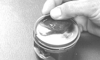
Inspecting Piston 1.Inspect the piston for cracks in the piston pin, dome, and skirt areas.
2.Inspect the piston for seizure marks or scuffing.
Repair with #400 grit wet-or-dry sandpaper and water or honing oil. NOTE: If scuffing or seizure marks are too deep to
correct with the sandpaper, replace the piston.
3.Inspect the perimeter of each piston for signs of excessive “blowby.” Excessive “blowby” indicates worn piston rings or an out-of-round cylinder.
Removing Piston Rings 1.Starting with the top ring, slide one end of the ring out of the ring-groove.
CC400D
2.Remove each ring by working it toward the dome of the piston while rotating it out of the groove. NOTE: If the existing rings will not be replaced with
new ones, note the location of each ring for proper installation. When installing new rings, install as a complete set only.
Measuring Piston-Ring End Gap (Installed) 1.Place each piston ring in the wear portion of the cylinder. Use the piston to position each ring squarely in the cylinder. 2.Using a feeler gauge, measure each piston-ring end gap. Acceptable ring end gap must not exceed specifications.
KM452
Measuring Piston Pin (Outside Diameter) and Piston-Pin Bore 1.Measure the piston pin outside diameter at each end and in the center. If measurement is not within specifications, the piston pin must be replaced.

2.Insert an inside dial indicator into the piston-pin bore. The diameter must not exceed specifications.
Take two measurements to ensure accuracy.
ATV-1069
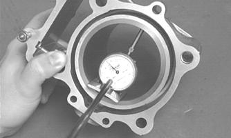
Measuring Piston Skirt/ Cylinder Clearance 1.Using a slide gauge and a dial indicator or a snap gauge, measure the cylinder bore diameter in three locations from top to bottom and again from top to bottom at 90° from the first measurements for a total of six measurements. The trueness (out-of-roundness) is the difference between the highest and lowest reading. Maximum trueness (out-of-roundness) must not exceed specifications.
CC127D
2.Measure the corresponding piston diameter at a point 18 mm above the piston skirt at a right angle to the piston-pin bore. Subtract this measurement from the measurement in step 1. The difference (clearance) must be within specifications.
Installing Piston Rings 1.Install ring expander (4) in the bottom groove of the piston; then install the thin oil rings (3) over the expander making sure the expander ends do not overlap. Stagger the end gaps of the upper and lower thin oil rings according to the illustration. NOTE: Note the direction of the exhaust side of the
piston (5) for correct ring end gap orientation.
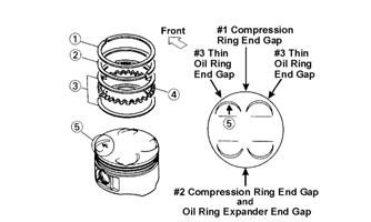
ATV-1085B
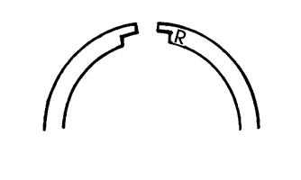
2.Install the compression rings (1 and 2) so the letter on the top surface of each ring faces the dome of the piston. Rotate the rings until the ring end gaps are on directly opposite sides of the piston according to the illustration.
726-306A
CAUTION
Incorrect installation of the piston rings will result in engine damage.
CYLINDER ASSEMBLY NOTE: If the cylinder cannot be trued, it must be
replaced.
Cleaning/Inspecting Cylinder 1.Wash the cylinder in parts-cleaning solvent. 2.Inspect the cylinder for pitting, scoring, scuffing, warpage, and corrosion. If marks are found, repair the surface using a surface plate. 3.Place the cylinder on the surface plate covered with #400 grit wet-or-dry sandpaper. Using light pressure, move the cylinder in a figure-eight motion. Inspect the sealing surface for any indication of high spots.
A high spot can be noted by a bright metallic finish.
Correct any high spots before assembly by continuing to move the cylinder in a figure-eight motion until a uniform bright metallic finish is attained.
CAUTION
Water or parts-cleaning solvent must be used in conjunction with the wet-or-dry sandpaper or damage to the sealing surface may result.
Inspecting Cam Chain Guide 1.Inspect cam chain guide for cuts, tears, breaks, or chips. 2.If the chain guide is damaged, it must be replaced.
Honing Cylinder 1.Wash the cylinder in parts-cleaning solvent. 2.Inspect the cylinder for pitting, scoring, scuffing, and corrosion. If marks are found, repair the surface using a #320 grit ball hone. NOTE: To produce the proper 60° cross-hatch pat-
tern, use a low RPM drill (600 RPM) at the rate of 30 strokes per minute. If honing oil is not available, use a lightweight petroleum-based oil. Thoroughly clean cylinder after honing using soap and hot water. Dry with compressed air; then immediately apply oil to the cylinder bore. If the bore is severely damaged or gouged, replace the cylinder.

CC390D
3.If any measurement exceeds the limit, replace the cylinder.
Installing Top-Side Components
A.Piston B.Cylinder 1.Install the piston on the connecting rod making sure there is a circlip on each side and the open end of the circlip is directed upwards or downwards. NOTE: The piston should be installed so the IN
mark is toward the intake (rear) side of the cylinder.
2.Place the two alignment pins into position. Place the cylinder gasket into position; then place a piston holder (or suitable substitute) beneath the piston skirt and square the piston in respect to the crankcase. 3.Lubricate the inside wall of the cylinder; then using a ring compressor or the fingers, compress the rings and slide the cylinder over the piston. Route the cam chain up through the cylinder cam chain housing; then remove the piston holder and seat the cylinder firmly on the crankcase.
4.Turn the cam chain tensioner screw clockwise to retract the tensioner spring.
CAUTION
The cylinder should slide on easily. Do not force the cylinder or damage to the piston, rings, cylinder, or crankshaft assembly may occur.
KM705
C.Cylinder Head D.Valve Cover NOTE: Steps 1-4 in the preceding sub-section must
precede this procedure.
5.While keeping tension on the cam chain, place the front cam chain guide into the cylinder.
6.Place the head gasket into position on the cylinder. Place the alignment pins into position; then place the head assembly into position on the cylinder making sure the cam chain is routed through the chain cavity.
CAUTION
Care should be taken that the bottom of the chain guide is secured in the crankcase boss.
CAUTION
Keep tension on the cam chain to avoid damaging the crankcase boss.
KM718A
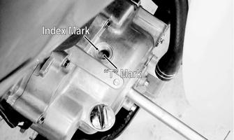
7.Turn the crankshaft as required to align the “T” mark on the rotor/flywheel with the index mark on the right-side crankcase cover.
KM779A
8.With the index hole in the camshaft gear directed away from the cylinder head and the two punch marks aligned with the cylinder head surface, install the timing gear into the cam chain and seat the camshaft into the camshaft journals.

KM715A
9.Install the two alignment pins; then install the camshaft holder and secure with the four cylinder head nuts and washer. Using a crisscross pattern, tighten to 18 ft-lb.
KM707A KM706A
10.Install the cam chain tensioner assembly and tighten the mounting cap screws to 9 ft-lb; then turn the tensioner screw counterclockwise to tension the cam chain.
KM705
11.Install the cam chain tensioner cover bolt and tighten to 24 in.-lb.
12.Check that the cam gear alignment marks are correctly oriented; then install and tighten the external cylinder head to cylinder cap screws to 7 ft-lb. 13.Install the cylinder head cover with a new O-ring and tighten securely.
KM703
14.Install the air pipe and vent hose using the existing cap screws and clamp.
KM937A

KM938A
15.Install the air hose into the cylinder head.
KM941A
Left-Side Components
NOTE: For efficiency, it is preferable to remove and disassemble only those components which need to be addressed and to service only those components. The technician should use discretion and sound judgment.
NOTE: The engine/transmission does not have to be
removed from the frame for this procedure.
AT THIS POINT
To service any one specific component, only limited disassembly of components may be necessary. Note the AT THIS POINT information in each sub-section.
Removing Left-Side Components
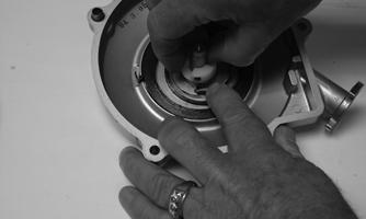
A.Recoil Starter 1.Remove the five recoil starter cover cap screws.
Remove the recoil starter assembly noting the location of the dowel pins. Note the condition of the recoil cover gasket. Replace if damaged.
AT THIS POINT
To service the recoil starter, see Servicing Left-Side Components sub-section.
B.V-Belt Cover C.Drive Pulley D.Driven Pulley/Centrifugal Clutch
Assembly NOTE: Step 1 in the preceding sub-section must
precede this procedure.
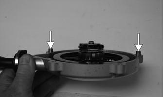
2.Remove the ten cap screws securing the V-belt cover; then remove the cover noting the location of the two dowel pins. Note the condition of the V-belt cover gasket. Replace if damaged.
KM253
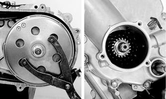
3.Using a suitable holder to prevent the drive pulley from turning, remove the drive face nut and starter ratchet; then remove the drive pulley face.
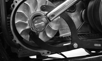
KM365
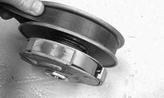
4.Hold the centrifugal clutch with a suitable holder; then remove the clutch retaining nut and clutch collar.

KM364
5.Remove the outer clutch housing; then remove the centrifugal clutch, driven pulley, and V-belt.
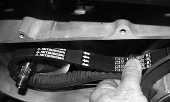
KM369
6.Remove the drive pulley collar and the movable drive face taking care not to loose the rollers.
Servicing Left-Side Components
RECOIL STARTER ! WARNING
Always wear safety glasses when servicing the recoil starter.
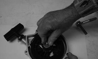
Removing/Disassembling 1.Remove the cap screws securing the recoil starter assembly to the V-belt cover; then remove the starter.
Account for two alignment pins.
KM413A
! WARNING
During the disassembling procedure, continuous backward pressure must be exerted on the reel so it does not accidentally unwind and cause injury.
2.Rotate the reel clockwise until the notch of the reel is near the rope guide in the case. Guide the rope into the notch and slowly allow the reel to unwind until all spiral spring tension is released.
3.Remove the cap screw. Account for the ratchet guide, spacer, and spring.
CAUTION
During the disassembling procedure, make sure all spring tension is released before continuing.

KM411
4.Carefully lift the reel free of the case making sure the spiral spring does not accidentally disengage from the case.
KM402A
! WARNING
Care must be taken when lifting the reel free of the case. Wear safety glasses to avoid injury.
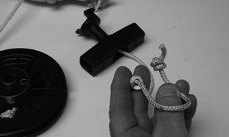
5.Remove the protective cover from the starter handle and pull the rope out of the handle; then untie the knot in the rope and remove the handle. Account for a flat washer.
KM408
NOTE: Do not remove the spiral spring unless
replacement is necessary. It should be visually inspected in place to save time. If replacement is necessary, follow steps 6-7.
6.Remove the spiral spring from the case by lifting the spring end up and out. Hold the remainder of the spring with thumbs and alternately release each thumb to allow the spring to gradually release from the case.
7.Unwind the rope from the reel and remove the rope.
Cleaning and Inspecting 1.Clean all components. 2.Inspect the springs and ratchet for wear or damage. 3.Inspect the reel and case for cracks or damage. 4.Inspect the shaft for wear, cracks, or damage. 5.Inspect the rope for breaks or fraying. 6.Inspect the spiral spring for cracks, crystallization, or abnormal bends.
7.Inspect the handle for damage, cracks, or deterioration.
Assembling/Installing 1.If removed, insert the spiral spring into the case with the outer end of the spring around the mounting lug in the case; then wind it in a counterclockwise direction until the complete spring is installed. NOTE: The spiral spring must seat evenly in the
recoil case.
KM402
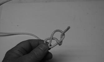
2.Insert the rope through the hole in the reel and tie a knot in the end; then wrap the rope clockwise around the reel leaving approximately 50 cm (20 in.) of rope free of the reel.
3.Apply low-temperature grease to the spring and hub. 4.Thread the end of the rope through the guide hole of the case; then thread the rope through the handle and washer and secure it with a double knot. Install the protective cover into the handle.
KM400
KM405
5.Align the inner hook of the spiral spring with the notch in the reel spacer.
KM402A
6.Install the ratchets making sure the ends are properly oriented on the reel.
KM397A
7.Install the spacer, spring, and the ratchet guide making sure the ratchet pins engage the guide.
KM401
8.Hold the ratchet guide down in place on the ratchet pins and secure with the cap screw coated with blue
Loctite #243. Tighten securely. 9.With the 50 cm (20 in.) of rope exposed, hook the rope in the notch of the reel. 10.Rotate the reel four turns clockwise; then release the rope from the notch and allow the rope to retract. 11.Pull the rope out two or three times to check for correct tension and ratchet extender.
KM412
NOTE: Increasing the rotations in step 10 will
increase spring tension.
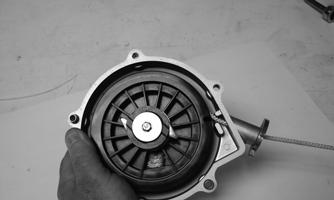
12.Place the recoil starter assembly into position on the left-side cover; then tighten the cap screws securely.
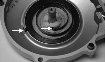
V-BELT COVER 1.Inspect the bearing for excessive wear, rough or binding when turning, seal condition, and secure mounting in the V-belt cover. NOTE: If the bearing is worn excessively, turns
roughly, or bearing seals are loose, the bearings must be replaced.
KM254
2.Inspect the V-belt cover for cracks, distortion, and loose alignment pins. NOTE: If the V-belt cover is cracked or distorted or
if the bearing is loose in the cover, the cover must be replaced.
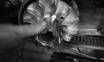
DRIVE PULLEY 1.Remove the ramp plate from the movable drive face; then inspect the ramp plate guides and weight roller for damage or excessive wear.
KM256
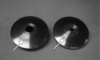
2.Inspect the face surfaces of the fixed and movable drive faces for grooving, nicks, or discoloration.
KM394A
3.Inspect the drive pulley collar for wear or damage.
Measure the outside diameter of the drive pulley collar sliding surface. The minimum service limit is 26.94 mm.
KM389
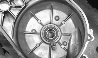
DRIVEN PULLEY/CENTRIFUGAL CLUTCH ASSEMBLY Disassembling ! WARNING
This procedure involves relaxing a compressed spring assembly. DO NOT attempt disassembling without the proper tools.
1.Place the driven pulley on a suitable spring compressor; then mark the pulley faces and centrifugal clutch for alignment during assembling.
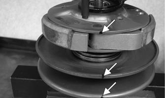
KM374A
2.Secure the centrifugal clutch with the spring compressor; then remove the drive plate nut.
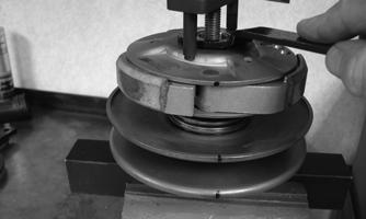
KM373
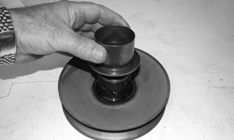
3.Release the spring pressure and remove the centrifugal clutch assembly from the driven pulley.

KM375
4.Remove the spring and spring seat; then remove the hub collar.
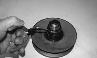
KM384
KM380
Inspecting 1.Inspect the pulley faces for wear, galling, or grooving.
KM394A
2.Inspect the O-rings on the movable face for nicks, tears, or swelling.
KM380A
3.Inspect two grease seals in the movable face for nicks, cuts, or damage.

KM380B

KM382A
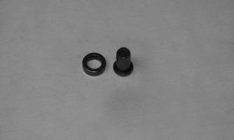
4.Inspect the pins and bushings for wear, flat spots, looseness, or cracking.
KM379
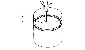
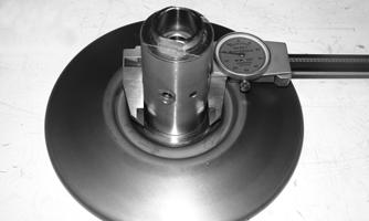
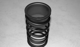
5.Measure the driven face spring free length. If the free length is less than 131 mm, the spring must be replaced.

KM376
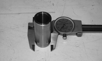
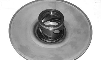
6.Measure the driven fixed face hub using a calipers.
The minimum service limit is 39.93 mm.
KM378
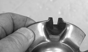
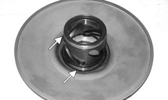
7.Measure the thickness of the centrifugal clutch shoe lining. The minimum service limit for the lining is 0.5 mm.
NOTE: If any shoe lining is below the service limit,
the complete set must be replaced.
Assembling 1.Place the fixed face of the driven pulley on the pulley compressor base. NOTE: Make sure the spacer is on the base or dam-
age to the fixed face will occur when the spring is compressed.
KX571
2.Apply multi-purpose grease to the O-rings and grease seals on the movable face; then install on the fixed face making sure the alignment marks are properly aligned.
KM374A
3.Install the pins and spacers into the fixed face hub; then pack the cam slots in the movable face with multi-purpose grease.
KM384
4.Install the spring seat over the hub and movable face hub.
KM385
5.Place the spring holder on the spring; then install the spring on the pulley assembly.
6.Place the centrifugal clutch assembly, drive plate nut, and clutch compressor adapter in position; then using the clutch compressor wing nut, compress the clutch spring and install the nut (lightly coated with red
Loctite #271).
KM373
7.Using a suitable holding fixture, tighten the drive plate nut (coated with red Loctite #271) to 43 ft-lb.
Installing Left-Side Components
A.Drive Pulley B.Driven Pulley/Centrifugal Clutch
Assembly C.V-Belt Cover 1.Install the movable drive face and drive pulley collar on the crankshaft.
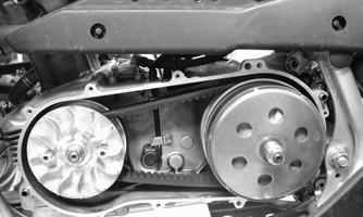
2.Open the faces of the driven pulley; then insert a suitable wedge between the faces to hold them apart. 3.Place the V-belt around the pulley and push the belt down between the pulley faces; then install the driven pulley/centrifugal clutch assembly onto the driveshaft. Loop the V-belt over the drive pulley collar.
KM262 KM369
4.Place the fixed drive face into position on the crankshaft and engage the splines making sure the splines extend beyond the pulley face hub.
KM263A
5.Install the starter ratchet on the crankshaft making sure to engage the splines; then secure with the flange nut and tighten to 68 ft-lb.
KM366
KM365
6.Install the centrifugal clutch housing and clutch collar; then secure with the flange nut and tighten to 40 ft-lb.
KM253

KM368
7.Install the alignment pins and a new gasket on the crankcase; then install the V-belt cover and secure with the cap screws. Tighten securely. 8.Install the recoil starter and secure with the cap screws. Tighten securely.
Right-Side Components
AT THIS POINT
To service center crankcase components only, proceed to Removing Right-Side Components.
NOTE: For efficiency, it is preferable to remove and
disassemble only those components which need to be addressed and to service only those components. The technician should use discretion and sound judgment.
NOTE: The engine/transmission does not have to be
removed from the frame for this procedure.
AT THIS POINT
To service any one specific component, only limited disassembly of components may be necessary. Note the AT THIS POINT information in each sub-section.
Removing Right-Side Components
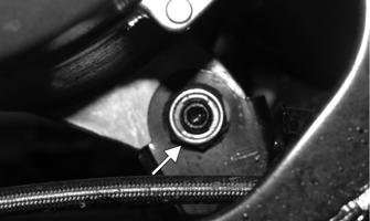
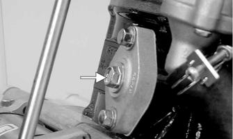
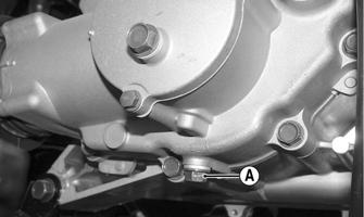
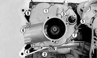
A.Transmission 1.Drain the transmission lubricant into a suitable container; then install the drain plug (A) and tighten to 21 ft-lb.
KM954B
NOTE: If the engine has not been removed, remove
the swing arm assembly (see Drive System — Rear Drive Axle — REMOVING).
2.Using a crisscross pattern, remove four cap screws securing the secondary driven bevel gear assembly to the transmission case cover; then remove the assembly. Account for an O-ring.

KM646A
3.Remove the three cap screws securing the secondary drive bevel gear cover; then remove the cover.
Account for a gasket.

KM649
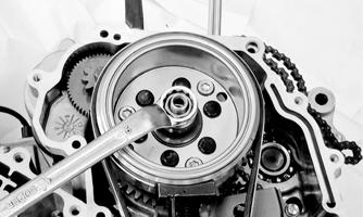
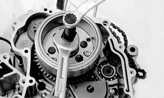
5.Using a Spanner Wrench to hold the centrifugal clutch housing, remove the nut securing the secondary drive bevel gear to the driveshaft.
KM650
NOTE: If the engine has been removed and the
left-side components are removed, install the centrifugal clutch housing on the driveshaft. If the left-side components have not been removed, see Removing Left-Side Components in this section. Remove only the V-belt cover.
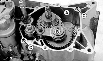
6.Remove the eight cap screws securing the transmission case cover to the transmission case; then remove the cover. Account for a gasket (A), the secondary drive bevel gear, washer (B), and two alignment pins (C).
KM651A KM652A
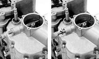
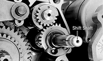
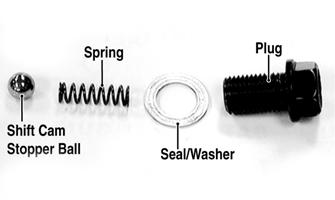
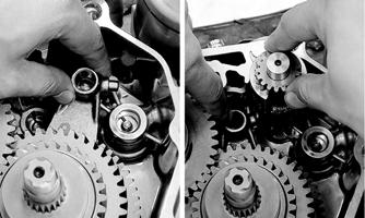
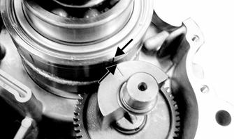
7.Remove the shift shaft; then remove plug, seal/washer, spring, and shift cam stopper ball.
KM677A
KM619A
8.Remove the shift fork guide shaft; then remove the upper shift fork and shift cam.
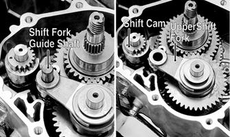
KM679A
9.Remove the lower shift fork.
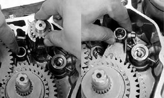
KM680
10.Remove the countershaft and driveshaft as an assembly.
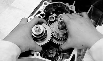
KM681
11.To disassemble the countershaft, use the following procedure:
A.Remove the thrust washer and high gear clutch dog.
KM684
B.Remove the high drive gear circlip and washer; then remove the high drive gear and thrust washer.
KM685
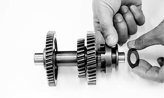
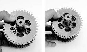
12.To disassemble the driveshaft, use the following procedure:
A.Remove the thrust washer; then remove the reverse gear.
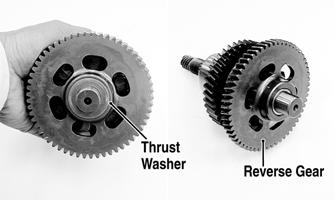
KM689A
B.Remove a thrust washer and the low/reverse clutch dog.
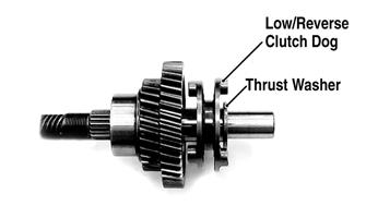
KM690A
C.Remove the low driven gear snap ring and washer; then remove the low driven gear and thrust washer.

KM692A
13.To disassemble the secondary driven bevel gear assembly, use the following procedure:
A.Secure the universal joint using a suitable vise; then engage the output end of the shaft with the universal joint.
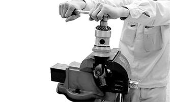
KM653
B.Remove the nut securing the driven bevel gear; then remove the gear. Account for a washer.
KM654
C.Remove the shaft and housing from the universal joint and remove the shaft from the housing. NOTE: If left-side components are still attached,
remove the centrifugal clutch/driven pulley.
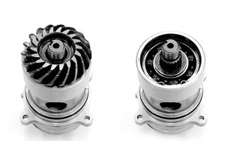
B. Water Pump C.Trigger Coil D.Stator Coil E.Rotor/Flywheel AT THIS POINT
To remove/service the water pump, see Fuel/Lubrication/Cooling.
14.Remove the right crankcase cover (see Fuel/Lubrication/Cooling — Water Pump). 15.Remove the trigger coil mounting screws; then remove the wire set plate.

KM772A
16.Remove the three cap screws securing the stator coil to the crankcase cover; then remove the stator coil and trigger coil.
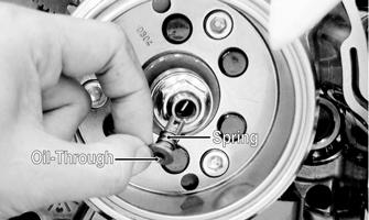
17.Remove the oil-through and spring from the end of the crankshaft; then hold the rotor/flywheel with an appropriate holding tool and remove the flywheel nut and washer. CAUTION
Use extreme care to avoid damaging or shorting the wiring.
KM774
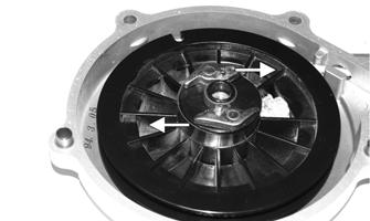
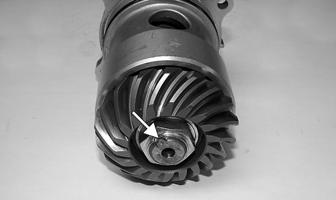
18.Install the flywheel puller and crankshaft protector; then remove the rotor/flywheel. Account for a key and the starter one-way clutch bearing.
KM775

KM766A
NOTE: The starter one-way clutch bearing is direc-
tion oriented and will only function if installed properly. Note the markings or arrows when removed.
F. Oil Pump NOTE: Steps 14-18 in the preceding sub-section
must precede this procedure.
AT THIS POINT
To service the stator coil, see Electrical System.
AT THIS POINT
To service the trigger coil, see Electrical System.
19.Remove the rotor/flywheel (see E. Rotor/Flywheel in this sub-section). 20.Remove the starter drive gear and place together with the rotor/flywheel to keep the one-way clutch bearing intact.

KM767A KM766A
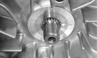
21.Remove the two cap screws securing the oil baffle to the crankcase and remove the baffle; then remove the snap ring securing the oil pump driven sprocket.

KM428
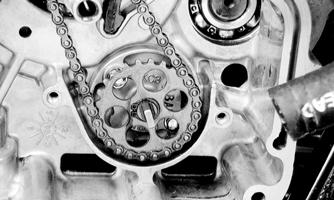
KM429
22.Remove the oil pump drive chain and oil pump driven sprocket. 23.Remove the two cap screws securing the oil pump to the crankcase and remove the oil pump.
Servicing Right-Side Components
TRANSMISSION Inspecting 1.Measure the shift fork guide shaft runout. If runout exceeds 0.03 mm, the shaft must be replaced.

KM623
2.Inspect the shift forks for distortion, discoloration, or excessive wear.
3.Inspect the shift cam groove and shift cam gear for excessive wear.
KM624
4.Inspect the shift shaft and gear for excessive wear.
Check that the spring is not broken.

KM683
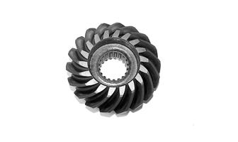
5.Inspect all gear teeth for chipping, discoloration, pitting, or excessive wear. Replace as required. 6.Inspect clutch dogs and mating surfaces for chipping, rounding, or excessive wear. Replace as required. 7.Inspect all bearings, bushings, seals, and shafts for proper fit, surface mating, or discoloration. Replace as required. 8.Inspect transmission housing and cover for cracks, scoring or galling of bearing bores, or case discoloration. 9.Inspect the drive and driven bevel gears for chipping, flaking, or excessive wear in the splines. Replace as required.
KM422
10.Inspect the secondary driven bevel gear housing for cracks, loose bearings, or signs of discoloration from heat. Replace as required. 11.Inspect the driven shaft for scoring, discoloration, or worn splines.

KM421
SECONDARY GEARS Checking Backlash 1.Remove the secondary drive bevel gear cover. 2.Mount a dial indicator so as to allow the tip to contact the secondary driven bevel gear. 3.Mount the indicator tip of the dial indicator on the secondary driven bevel gear (centered on the gear tooth). 4.While rocking the driven bevel gear back and forth, note the maximum backlash reading on the gauge. 5.Acceptable backlash range is 0.03-0.15 mm (0.001-0.006 in.).
Correcting Backlash NOTE: If backlash measurement is within the
acceptable range, no correction is necessary.
1.If backlash measurement is less than specified, remove an existing driven bevel gear shim, measure it, and install a new thinner shim. 2.If backlash measurement is more than specified, remove an existing driven bevel gear shim, measure it, and install a thicker shim.
NOTE: Continue to remove, measure, and install
until backlash measurement is within tolerance. Note the following chart.
Checking Tooth Contact NOTE: After correcting backlash of the secondary
driven bevel gear, it is necessary to check tooth contact.
Backlash Measurement Shim Correction
Under 0.03 mm (0.001 in.) Decrease Shim Thickness
At 0.03-0.15 mm (0.001-0.006 in.) Over 0.15 mm (0.006 in.) No Correction Required
Increase Shim Thickness
1.Remove the secondary driven output shaft assembly from the left-side crankcase half.
2.Clean the secondary driven bevel gear teeth of old oil and grease residue. 3.Apply a thin, even coat of a machinist-layout dye to several teeth of the gear. 4.Rotate the secondary driven bevel gear several revolutions in both directions.
5.Examine the tooth contact pattern in the dye and compare the pattern to the illustrations.
ATV-0103
ATV-0105 ATV-0104
Correcting Tooth Contact NOTE: If tooth contact pattern is comparable to the
correct pattern illustration, no correction is necessary.
If tooth contact pattern is comparable to an incorrect pattern, correct tooth contact according to the following chart.
Tooth Contact
Contacts at Top Contacts at Root
Shim Correction
Increase Shim Thickness Decrease Shim Thickness
NOTE: To correct tooth contact, increase or
decrease shims as necessary on both secondary drive and driven gears equally. Use the “Tooth Contact/Shim Correction” chart above for shim selections.
CAUTION
After correcting tooth contact, backlash must again be checked and corrected (if necessary). Continue the correcting backlash/correcting tooth contact procedures until they are both within tolerance values.
Assembling 1.Using the appropriate bearing and seal drivers, install any required bearings and seals in the transmission case and case cover.
KM696
2.Replace any required bearings and seals in the secondary driven bevel gear shaft case. Apply oil to all seal lips.

KM695
3.Apply oil to the secondary driven bevel gear shaft; then install the bearing into the case.

KM420
4.Install the flat thrust washer and driven bevel gear on the driven shaft; then using the universal joint and vise to hold the shaft, install a new nut and tighten to 72 ft-lb.

KM425
5.Use a center punch to stake the nut to the driven shaft.
KM426A
6.Install the high drive gear thrust washer on the countershaft; then install the high drive gear and secure with a circlip.
KM685A
7.Install the high gear clutch dog and flat washer. At this point, the countershaft is ready for installation.
KM684
8.Install the low driven gear washer on the driveshaft; then install the low driven gear and thrust washer.
Secure with a snap ring.
KM692A
9.Install the low/reverse clutch dog and spacer washer; then install the reverse gear and reverse gear thrust washer. At this point, the driveshaft is ready for installation.
KM690A
10.Apply clean engine oil to the assembled shafts and gears; then install the countershaft and driveshaft simultaneously into the transmission case.
KM699
11.Install the low/reverse shift fork into the low/reverse clutch dog; then install the shift cam into the transmission case and engage the shift fork pawl in the appropriate shift cam groove.
KM700
12.Install the high shift fork into the high clutch dog; then engage the shift fork pawl into the appropriate shift cam groove. 13.Install the shift fork shaft making sure that the shift fork pawls remain engaged in the shift cam; then install the shift cam stopper ball, spring, seal/washer, and plug (threads coated with red Loctite #271).
Tighten to 20 ft-lb.
KM619A
14.Install the shift shaft making sure to align the timing mark between the two marks on the shift cam.
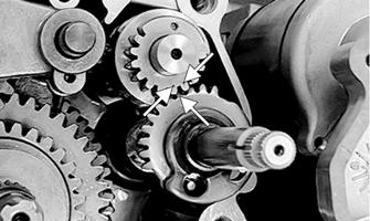
KM702A
15.Install the two alignment pins, gasket, and transmission case cover and secure with eight cap screws.
Tighten in a crisscross pattern to 20 ft-lb.
KM651A
16.Install a spacer washer and the drive bevel gear on the driveshaft; then while holding the centrifugal clutch housing with an appropriate holder, secure the bevel gear with a new nut and tighten to 72 ft-lb.
KM650
17.Use a center punch to stake the nut to the driveshaft. 18.Apply clean engine oil to a new O-ring and install in the groove of the secondary driven bevel gear housing; then with the index marks aligned, install the secondary driven bevel gear assembly in the transmission case.

KM673
19.Loosely secure the secondary driven bevel gear assembly using the four cap screws; then using a crisscross pattern, tighten the cap screws until fully seated in the transmission housing.
KM646A
Installing Right-Side Components
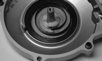
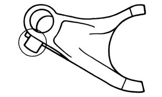
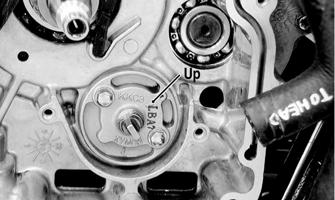
A.Oil Pump 1.Install the oil pump with the arrow on the pump body directed upward; then secure with the two cap screws and tighten securely. Make sure the shaft turns freely after installing.
KM434A
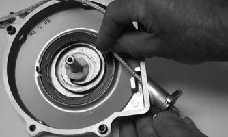
2.Install the oil pump driven sprocket and drive chain; then secure the driven sprocket with a snap ring. 3.Install the oil pump baffle and tighten the cap screws securely.
B.Rotor/Flywheel C.Trigger Coil D.Stator Coil 4.Install the starter idler shaft and gear in the crankcase; then install the starter driven gear on the crankshaft.
KM767
NOTE: Make sure the crankshaft and rotor/fly-
wheel contact surfaces are clean and dry before installing the flywheel.
5.Install the key in the crankshaft; then with the starter one-way bearing correctly installed, place the rotor/flywheel onto the crankshaft and position the aligning keyway with the key. 6.Secure the rotor/flywheel on the crankshaft with the nut and tighten to 47 ft-lb; then install the spring and oil-through in the crankshaft.
KM773A
7.Install the trigger coil and stator coil in the right-side crankcase cover; then secure with the existing hardware and tighten securely.
E.Water Pump AT THIS POINT
To install the water pump, see Fuel/Lubrication/Cooling.
F.Transmission See Servicing Right-Side Components in this sub-section.
Center Crankcase Components
NOTE: This procedure cannot be done with the
engine/transmission in the frame. Complete Removing procedures for Top-Side, Left-Side, and Right-Side must precede this procedure.
NOTE: For efficiency, it is preferable to remove and
disassemble only those components which need to be addressed and to service only those components. The technician should use discretion and sound judgment.
Separating Crankcase Halves
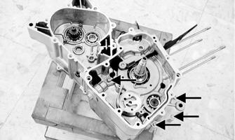
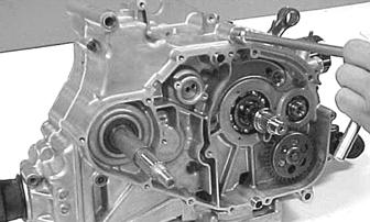
1.Remove the left-side and right-side cap screws securing the crankcase halves noting the position of the different-sized cap screws for joining purposes.
KM720A
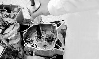
2.Using Crankcase Separator/Crankshaft Remover and tapping lightly with a rubber mallet, separate the crankcase halves. Account for two alignment pins and a gasket.
Disassembling Crankcase Half
1.Remove the crankshaft from the left crankcase half.
KM721
2.Remove the balancer shaft from the left crankcase half.

KM722
AT THIS POINT
To service crankshaft assembly, see Servicing Center Crankcase Components sub-section.
Servicing Center Crankcase Components
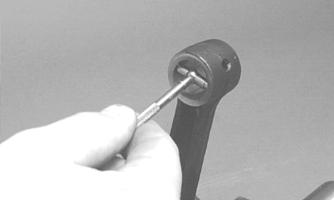
CRANKSHAFT ASSEMBLY Measuring Connecting Rod (Small End Inside Diameter) 1.Insert a snap gauge into the upper connecting rod small end bore; then remove the gauge and measure it with micrometer.
CC290D
2.Maximum diameter must not exceed specifications.
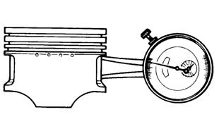
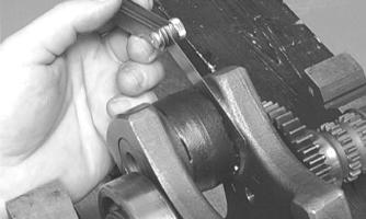
Measuring Connecting Rod (Small End Deflection) 1.Place the crankshaft on a set of V-blocks and mount a dial indicator and base on the surface plate. Position the indicator contact point against the center of the connecting rod small end journal. 2.Zero the indicator and push the small end of the connecting rod away from the dial indicator. 3.Maximum deflection must not exceed specifications.
Measuring Connecting Rod (Big End Side-to-Side) 1.Push the lower end of the connecting rod to one side of the crankshaft journal.
CC289D
3.Acceptable gap range must be within specifications.
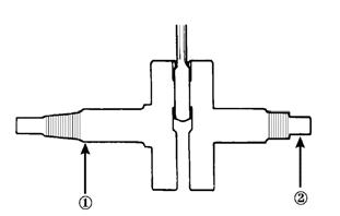
Measuring Crankshaft (Runout) 1.Place the crankshaft on a set of V blocks.
2.Mount a dial indicator and base on the surface plate.
Position the indicator contact at point 1 of the crankshaft.
ATV-1074
3.Zero the indicator and rotate the crankshaft slowly.
CAUTION
Care should be taken to support the connecting rod when rotating the crankshaft.
4.Maximum runout must not exceed specifications. NOTE: Proceed to check runout on the other end of
the crankshaft by positioning the indicator contact at point 2 and following steps 3-4.
Measuring Crankshaft (Web-to-Web) 1.Using a calipers, measure the distance from the outside edge of one web to the outside edge of the other web.
ATV-1017
2.Acceptable width range must be within specifications.
CRANK BALANCER SHAFT Inspecting Inspect the gear teeth and bearing surfaces for chips, discoloration, or excessive wear.
KM724
Assembling Crankcase Half
NOTE: For ease of assembling, install components
on the left-side crankcase half.
To assemble center crankcase components, install the balancer shaft into the left-side crankcase half; then align the timing mark on the balancer shaft with the timing mark on the crankshaft. Install the crankshaft.
KM728A
Joining Crankcase Halves
1.Verify that the alignment pins and a new gasket are in place and that both case halves are clean and grease free. Place the right-side half onto the left-side half.
2.Using a plastic mallet, lightly tap the case halves together until cap screws can be installed. 3.From the right side, install the crankcase cap screws noting the location of the different-sized cap screws; then tighten only until snug. NOTE: Rotate the crankshaft back and forth to
ensure no binding or sticking occurs while tightening the cap screws.

MD1008
4.From the left side, install the remaining crankcase cap screws; then tighten only until snug. NOTE: Rotate the crankshaft back and forth to
ensure no binding or sticking occurs while tightening the cap screws.
CC871
5.In a crisscross/case-to-case pattern, tighten the cap screws until the halves are correctly joined; then tighten to 8 ft-lb. NOTE: Rotate the crankshaft back and forth to
ensure no binding or sticking occurs.
AT THIS POINT
After completing center crankcase components, proceed to Installing Right-Side Components, to Installing Left-Side Components, and to Installing Top-Side Components.
Installing Engine/Transmission
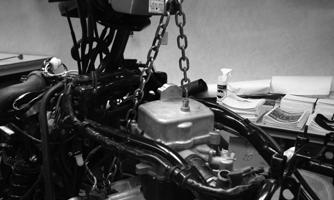
1.Attach a suitable engine lift to the front engine mounting boss; then lift the engine/transmission assembly into the frame from the left side. The front of the engine/transmission should go in first.
KM331
2.Lifting the front of the engine/transmission, move the assembly forward sufficiently to clear the rear engine mounts; then engage the secondary bevel driveshaft into the universal joint splines.
KM328
3.Slide the engine/transmission rearward into the rear engine mounts; then install the rear through-bolts and nuts. Do not tighten at this time. 4.Remove the engine lift from the front engine mounting boss; then install the engine mounting brackets to the frame. Finger tighten only.
KM414A
6.Tighten the nuts on the two rear and one front through-bolt to 29 ft-lb. 7.Connect the shift linkage using the existing hardware.
8.Install the output drive boot onto the bevel driven gear housing and secure with the existing clamp.
KM315A
9.Connect the V-belt cooling boots to the V-belt housing and secure with the existing hose clamps.
KM307A
10.Connect the engine ground wire to the engine; then connect the starter positive wire to the starter using the existing hardware. Tighten securely.
KM319A
11.Connect the coolant temperature sensor; then connect the trigger coil connector, shift position connector, and stator connector.
KM324A
KM347A
12.Install the ignition coil (see Electrical System). 13.Install the carburetor (see Fuel/Lubrication/Cooling). 14.Install the muffler assembly (see Steering/Body/Controls). 15.Install the gas tank and air filter (see Fuel/Lubrication/Cooling). 16.Install the fenders and front rack; then install the side panels (see Steering/Body/Controls). 17.Install the battery; then connect the positive and negative battery cables. 18.Pour in the recommended amount and grade of engine coolant, engine oil, and transmission lubricant.
19.Start the engine and allow it to warm up; then check all fluid levels and add as required.