15 minute read
Drive System

SPECIAL TOOLS A number of special tools must be available to the technician when performing service procedures in this section. Refer to the current Special Tools Catalog for the appropriate tool description. NOTE: When indicated for use, each special tool
will be identified by its specific name, as shown in the chart below, and capitalized.
NOTE: Special tools are available from the Textron
Off Road Service Parts Department.
Description
Pivot Lock Nut Wrench Rear Axle Nut Wrench Pinion Gear Bearing Nut Wrench Pinion Puller V Blocks
p/n
0444-201 0444-198 0444-203 0444-202 0644-535
Rear Drive Axle
REMOVING 1.Secure the ATV on a support stand to elevate the rear wheels.
2.Compress the brake lever and engage the brake lever lock; then remove the rear wheels and hub caps. 3.Remove the cotter pins and rear hub nuts; then remove the hubs.
4.Disengage the brake lever lock; then remove the rear brake calipers and brake disc.
! WARNING
Make sure the ATV is solidly supported on the support stand to avoid injury.
NOTE: Do not apply the brakes with the calipers
removed. The brake pistons will be pushed out and brake fluid will be spilled.
KM505
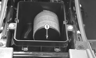
5.Remove the rear drive gear case; then drain the gear case.
KM504
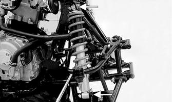
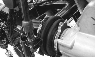
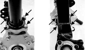
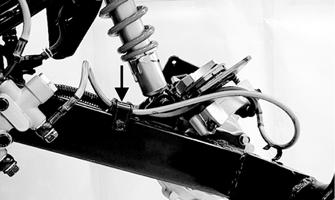
7.Remove the clamp securing the brakeline hose to the swing arm; then remove the lower rear shock absorber mounting nut and bolt.
KM505
8.Remove the left and right pivot caps; then remove the right-side pivot bolt.
KM506
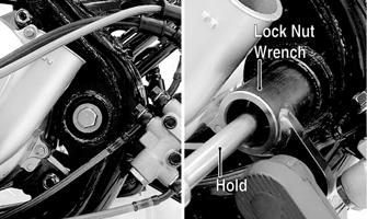
9.From the left side, remove the pivot lock nut using
Pivot Lock Nut Wrench; then remove the left pivot adjusting bolt.
KM533B
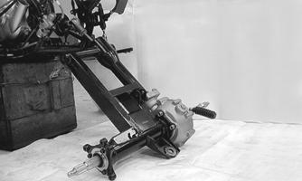
10.Remove the swing arm assembly. Account for the driveshaft spring.
KM508
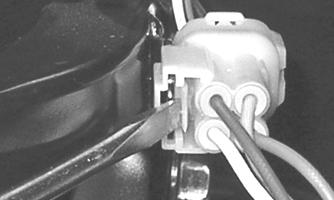
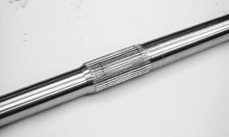
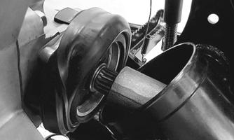
11.Disengage the universal joint from the transmission output shaft splines and set the driveshaft aside.

KM509
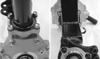
12.Remove the eight cap screws securing the swing arm to the final drive gear case.
KM513
13.Support the swing arm from the right side; then using a rubber mallet, drive the axle shaft from the swing arm tube. Account for two O-rings.

KM536

KM537
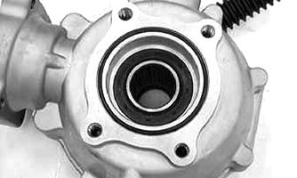
14.Place the right end (shorter length) of the axle on a wood block; then using a rubber mallet, drive the gear case from the axle.
KM538
CAUTION
Support the gear case by hand or damage to the gear case could occur as it will fall free once it clears the splined portion of the axle.
CLEANING AND INSPECTING 1.Clean all parts with parts-cleaning solvent and dry with compressed air. 2.Inspect all seals for nicks, tears, or deterioration.
KM519
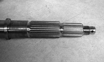
3.Inspect all splines and hubs for excessive wear, chips, cracks, or distortion.

KM539
KM540
4.Check that all bearings turn freely and smoothly and are not worn, discolored, or missing dust seals. 5.Inspect brake components for leaks, excessive wear, or discoloration.
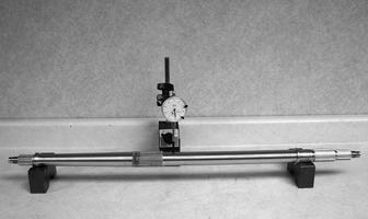
6.Check the axle shaft for runout using a dial indicator and suitable supports. Maximum runout is 3 mm (0.12 in.). NOTE: Axle runout is equal to 1/2 the total dial
indicator reading.
KM543
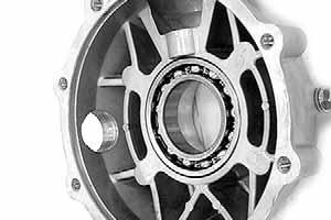
7.Check the final drive gear case assembly for smooth gear operation. If gears are noisy or if there is any catching or binding, the gear case assembly must be repaired.
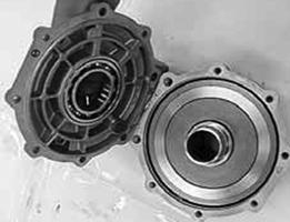
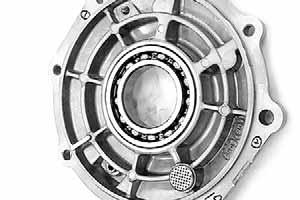
DISASSEMBLING 1.Remove the cap screws securing the gear case cover to the gear case; then remove the gear case cover and right ring gear shim.
KM918
KM919A
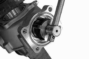
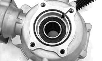
2.Remove the oil seal from the front of the gear case; then using the Pinion Gear Bearing Nut Wrench, remove the pinion nut.

KM920A
KM921
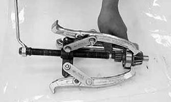
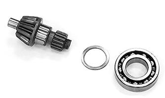
3.Remove the pinion shaft using the pinion puller; then using a three-jaw puller, remove the pinion bearing.
Account for the pinion shim.
KM922
KM923 KM924A
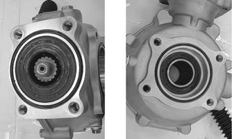
4.Remove the oil seals from the case and cover; then drive the bearings out of the case.

KM925
KM926
KM927
KM928
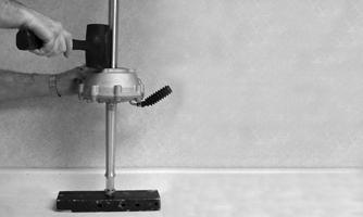
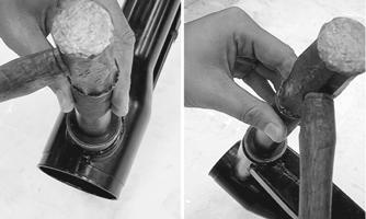
5.Heat the gear case to approximately 180° F and using a blind-bushing puller, remove the pinion needle bearing.
CLEANING AND INSPECTING 1.Clean all components in parts cleaning solvent and dry with compressed air. 2.Inspect all bearings for excessive wear, discoloration, roughness in turning, or flaking. 3.Inspect gears for excessive wear, chipped teeth, flaking, or discoloration. 4.Inspect the gear case and cover for cracks, warpage, or scoring of bearing bores. 5.If seals have not been removed and will be reused, inspect for nicks, tears, missing tension springs, or excessive wear on lips.
ASSEMBLING 1.Drive the bearings into the gear case and gear case cover using an appropriate bearing driver. Make sure the bearing is firmly seated.
KM926 KM928
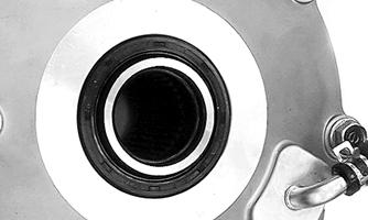
2.Apply grease to the seal lips; then using a seal driver, drive the seals into the gear case and cover (flat side out) until flush with the seal bore.

KM927A
KM925A
3.Drive a new pinion needle bearing into the gear case; then apply molybdenum disulfide grease to the needle bearing. Secure with the snap ring. 4.If the pinion bearing was removed from the pinion, install the shim and bearing on the pinion shaft with the marked-side of the bearing directed toward the front of the pinion shaft.
KM924
KM935

NOTE: When the gear set, ring gear, ring gear bear-
ing, and/or gear case is being replaced, use a 2 mm (0.08 in.) thick shim for initial set-up.
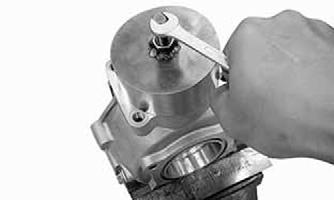
5.Drive the pinion assembly into the gear case seating the bearing firmly; then secure with a new lock nut and using the pinion lock nut wrench, tighten to 72 ft-lb.
KM920A
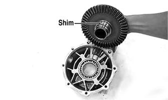
6.Apply grease to the pinion seal lips and install into the gear case until fully seated; then apply a light coating of machinist’s layout dye or paste to several ring gear teeth. 7.Install the proper shims on the ring gear and install into the gear case; then install the case cover and secure with the case cap screws. Tighten in a crisscross pattern while rotating the pinion gear.
Checking Tooth Contact 1.Rotate the ring gear several turns in either direction; then check gear contact through the oil filler hole. 2.Examine the tooth contact pattern in the dye and compare the pattern to the illustrations.
ATV-0103
ATV-0105
ATV-0104
Correcting Tooth Contact NOTE: If tooth contact pattern is comparable to the
correct pattern illustration, no correction is necessary.
If tooth contact pattern is comparable to an incorrect pattern, correct tooth contact according to the following chart.
After tooth contact is corrected, gear backlash must be checked.
Checking Backlash 1.Mount a dial indicator through the oil fill plug to contact a tooth on the ring gear; then “zero” the dial indicator.
Tooth Contact
Contacts at Top Contacts at Root
Shim Correction
Decrease Shim Thickness Increase Shim Thickness
KM936
2.While locking the pinion shaft to prevent it from turning, rock the ring gear back and forth and record the measurement. Standard backlash should be 0.05-0.25 mm (0.002-0.010 in.). Maximum service limit is 0.4 mm (0.016 in.). 3.Remove the dial indicator and rotate the ring gear 120°; then repeat steps 1-2. 4.Repeat step 3 for a total of three measurements; then compare the difference between the three. Maximum allowable difference is 0.2 mm (0.08 in.). NOTE: If the difference in measurements exceeds
specifications, the bearings are not installed squarely or the gear case is warped. If backlash is not within specifications, correct using the following chart.

NOTE: Always change both shims by the same
amount on opposite sides. If left shim is increased, right shim must be decreased by the same amount.
Backlash Ring Gear Left Side Ring Gear Right Side
Insufficient Decrease Shim Increase Shim Excessive Increase Shim Decrease Shim
5.After backlash is corrected, recheck gear tooth contact. Repeat Correcting Tooth Contact and Checking
Backlash until both are within specifications. 6.When tooth contact and backlash are within specification, remove the cap screws securing the cover to the gear case. 7.Clean any oil from the mating surfaces; then apply an even coat of silicone sealant to the mating surfaces and install the gear case covers. 8.Install six 8 mm and two 10 mm cap screws and while rotating the pinion gear, tighten in a crisscross pattern to the specified torque (8 mm cap screws to 19 ft-lb, 10 mm cap screws to 36 ft-lb).
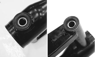
REPLACING SWING ARM SEALS AND BEARINGS To replace damaged or worn seals and bearings in the swing arm assembly, use the following procedure. 1.Remove the dust seals from the swing arm pivot; then using a slide hammer and bearing puller, remove the pivot bearings.

KM521
2.Drive in new pivot bearings until fully seated; then install new dust seals.
KM522
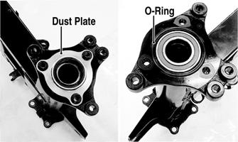
3.Remove the three cap screws, the dust plate, and one
O-ring from the left axle housing on the swing arm; then from the right side, drive out the axle bearing.
KM523A
4.Using a suitable bearing driver, install the new axle bearing into the axle housing; then install the O-ring and dust plate. Tighten the three cap screws securely.
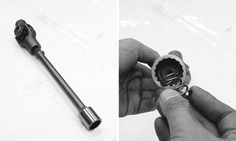
INSTALLING 1.Install new O-rings in the grooves of the gear case; then grease the center splines of the axle and install in the gear case from the left side.
KM527
2.Install the rear axle and gear case into the right side of the swing arm; then secure the gear case to the swing arm assembly with the eight cap screws.
Tighten to 50 ft-lb.
KM528A
3.Apply grease to the universal joint splines and driveshaft splines; then install the driveshaft spring into the driveshaft.
KM529
NOTE: Apply a liberal amount of grease to the
driveshaft splines and the driveshaft spring. This will aid in keeping the spring in position while assembling.
4.Insert the driveshaft assembly into the swing arm tube; then engage the driveshaft splines with the pinion shaft splines in the rear drive gear case.

KM530
5.Pack approximately 3g (0.1 oz) of grease into each swing arm pivot bearing cavity; then apply grease to the lips of the dust seals.
KM531
6.Align the swing arm assembly in the frame and engage the universal joint onto the splines of the secondary driven bevel gear shaft.
KM532
7.Install the right pivot bolt and left pivot adjusting bolt and tighten securely; then move the swing arm up and down to seat the bearings. Tighten the left pivot bolt to 36 in.-lb and the right pivot bolt to 82 ft-lb.
8.Install the left pivot lock nut; then while holding the left pivot adjusting bolt, use Pivot Lock Nut Wrench to tighten the lock nut to 82 ft-lb.
KM533B
9.Install the shock absorber using the existing hardware and tighten to 29 ft-lb; then install the brakeline hose clamp on the swing arm and tighten securely.
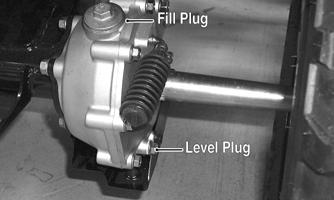
KM505A
10.Tighten the final drive gear case drain plug securely; then remove the fill plug and level plug.
KM131A
11.Pour the recommended gear lubricant into the fill hole until lubricant is visible on the threads of the level hole; then install the level plug and the fill plug and tighten securely. 12.Install the rear drive gear case guard and tighten the cap screws securely. 13.Apply grease to the brake disc hub and wheel hubs; then install the disc and rear hubs.

KM502
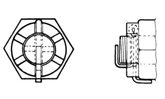
14.Install the hub nuts and tighten to 72 ft-lb; then install new cotter pins and bend as shown.
KM469
15.Install the rear brake calipers and tighten to 25 ft-lb. 16.Install the rear hub caps; then install the rear wheels and tighten in a crisscross pattern to 40 ft-lb. 17.Remove the ATV from the support stand.
Front Brake Lever/Master Cylinder Assembly
NOTE: The master cylinder is a non-serviceable
component; it must be replaced as an assembly.
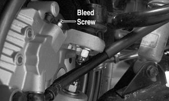
REMOVING 1.Connect a clear hose to the bleed screw on either front brake caliper; then open the bleed screw and pump the brake fluid into a suitable container. Close the bleed screw.
CAUTION
Brake fluid is highly corrosive. Do not spill brake fluid on any surface of the ATV.
KM116A
NOTE: Do not reuse brake fluid. When exposed to
air, brake fluid rapidly absorbs moisture.
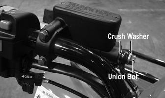
2.Remove the brakeline hose union bolt; then remove the cap screws securing the master cylinder assembly to the handlebar. Discard the crush washers from the union bolt.
KM800A
3.Remove the brake lever, brake light switch, and brake lever lock.
4.Remove the brake master cylinder by removing the two bolts securing it to the handlebar.
INSPECTING 1.Inspect the pivot bolt securing the brake lever for wear.
2.Inspect the brake lever for elongation of the pivot hole.
3.Inspect the reservoir for cracks and leakage. 4.Inspect the brake hose for cracks and deterioration and the condition of the fittings (threaded and compression). 5.Inspect the brake light switch for corrosion, cracks, missing or broken mounting tabs, or broken and frayed wiring. NOTE: If the brake light switch is defective, see
Electrical System — Lights.
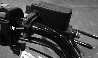
INSTALLING 1.Install the brake light switch on the master cylinder; then install the brake lever and brake lever lock. 2.Install the master cylinder assembly on the handlebar engaging the alignment stud in the hole in the handlebar; then secure with the master cylinder clamp and two cap screws. Make sure the UP arrow on the clamp is directed upward.
KM800C
3.Tighten the cap screws to 13 ft-lb. 4.Using new crush washers, secure the brake hose to the master cylinder with the brake hose union bolt.
Tighten to 25 ft-lb.
KM800A
5.Fill the master cylinder with DOT 4 brake fluid; then bleed the system (see Periodic Maintenance/Tune-Up - Hydraulic Brake Systems).
Auxiliary Brake Pedal/Master Cylinder Assembly
NOTE: The auxiliary brake master cylinder is a
non-serviceable component; it must be replaced as an assembly.
REMOVING 1.Connect a clear plastic hose to the appropriate bleed screw on the rear brake caliper; then loosen the bleed screw and pump the foot brake until the fluid is pumped into a suitable container.
CAUTION
Brake fluid is highly corrosive. Do not spill brake fluid on any surface of the ATV.
2.Compress the reservoir clamp and remove the reservoir hose; then remove the union bolt. Account for and discard two crush washers.
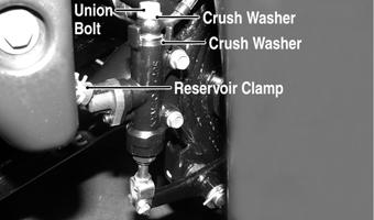
KM801A
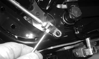
3.Remove the cotter pin from the clevis pin and remove the clevis pin; then remove the two cap screws securing the master cylinder to the frame and remove the master cylinder.

KM801B
4.Loosen the jam nut; then remove the clevis and adjuster nut.
INSTALLING 1.Install the jam nut; then install the clevis and adjuster nut. Finger-tighten only at this time. 2.Secure the master cylinder to the frame with the two cap screws and tighten securely. 3.Using two new crush washers, connect the brake hose to the master cylinder with the union bolt; then making sure the spring clamp is seated securely, connect the reservoir hose to the master cylinder.
Tighten the union bolt to 25 ft-lb. 4.Making sure the brake pedal is fully released and against the stop, turn the clevis and adjuster nut until the hole in the clevis is aligned with the hole in the brake pedal lever; then tighten the jam nut securely.
CD476

KM801C
5.Fill the master cylinder reservoir with DOT 4 brake fluid and bleed the system (see Periodic Maintenance/Tune-Up - Hydraulic Brake Systems).
Troubleshooting Drive System
Troubleshooting Brake System
Problem: Power not transmitted from engine to wheels Condition Remedy
1. Rear axle shaft serration worn — broken
1.Replace shaft
Problem: Braking poor Condition Remedy
1. Pad worn 1.Replace pads 2. Pedal free-play excessive 2.Adjust free-play 3. Brake fluid leaking 3.Repair — replace hydraulic system 4. Hydraulic system entrapped air 4.Bleed hydraulic system 5. Master cylinder/brake cylinder seal worn 5.Replace appropriate cylinder
Problem: Brake lever travel excessive Condition Remedy
1. Hydraulic system entrapped air 1.Bleed hydraulic system 2. Brake fluid low 2.Add fluid to proper level/bleed system 3. Brake fluid incorrect 3.Replace with correct fluid 4. Piston seal — cup worn 4.Replace master cylinder
Problem: Brake fluid leaking Condition Remedy
1. Connection joints loose 1.Tighten joint 2. Hose cracked 2.Replace hose 3. Piston seal worn 3.Replace master/brake cylinder