15 minute read
Steering/Body/Controls

The following steering components should be inspected periodically to ensure safe and proper operation:
A.Handlebar grips not worn, broken, or loose.
B.Handlebar not bent or cracked and has equal and complete full-left and full-right turning capability.
C.Steering post bearing assembly/bearing housing not broken, worn, or binding.
D.Ball joints not worn, cracked, or damaged.
E.Tie rods not bent or cracked.
F.Knuckles not worn, cracked, or damaged.
G.Cotter pins not damaged or missing. The frame, welds, and racks should be checked periodically for damage, bends, cracks, deterioration, broken components, and missing components.
Front Rack/Body Panel/Fender
REMOVING 1.Remove the seat.
2.Release both headlight connectors from the frame; then disconnect the headlight connectors from the main harness.
NOTE: Use a small screwdriver to disengage the tab
connector allowing the connector assembly to be removed from the frame.
KC223
3.Remove the Phillips-head screws securing the front rack over-mold to the rack; then remove the four cap screws securing the rack to the frame.
XA002
XA061A
4.Remove the two reinstallable rivets securing the steering post cover; then remove the cover.
XA062A
5.Remove the gas tank cap and two reinstallable rivets securing the gas tank cover. Slide the cover forward to remove.
XA063

XA069
6.Remove the Phillips-head screws with lock nuts and three cap screws securing each footwell to the vehicle. Remove the footwells.

XA064A
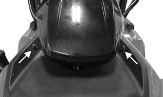
7.Remove the four cap screws securing the rear section of the front body panel to the frame; then remove the two cap screws securing the body panel to the gas tank.
XA065A XA067
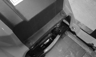
9.From within the front fascia, remove the two cap screws securing the fascia to the front bumper. From the front of the vehicle, remove the two cap screws securing the front of the fascia to the bumper.
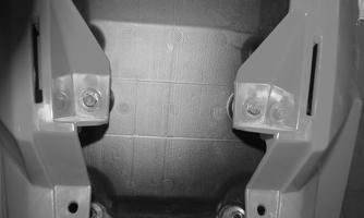

XA068A
XA070
10.Remove the Allen-head screw securing the shift knob to the shift lever. Turn the steering wheel full left and remove the front body panel.
CLEANING AND INSPECTING 1.Clean all body components with soap and water. 2.Inspect the body and fenders for cracks. 3.Inspect threaded areas of all mounting studs for stripping. 4.Inspect for missing decals.
INSTALLING 1.Place the front panel assembly onto the frame.
Loosely install the four cap screws located under the seat.
XA072
4.Secure the front body panel to the gas tank; then install both footwells.
XA065A
2.Secure the two cap screws securing the lower fascia to the front bumper; then from within the front bumper assembly, secure the additional two caps screws to the frame. Tighten the cap screws from step 1.
XA066
XA070
XA068A
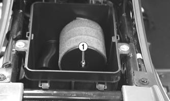
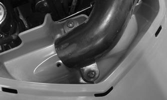
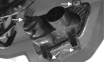
3.Secure the shift knob to the shift lever using the
Allen-head screw. Secure the CVT intake tube using the two machine screws. Connect each headlight connector; then secure the connectors to the frame via the locking tabs.
XA064A
5.Install the gas tank cover making sure the locating tabs properly align with and engage the front body panel. Secure the gas tank cover with the two reinstallable rivets. Install and secure the steering post cover.
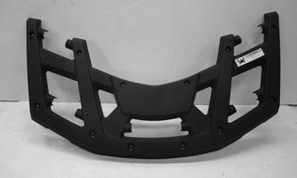
6.Place the front rack into position and secure using the four cap screws. Install the front over-mold onto the front rack using the self-tapping screws.
Front Fascia/Headlight
REMOVING 1.Release each locking tab securing each headlight connector to the frame; then disconnect each connector.
XA072
2.Remove the cap screws securing each headlight assembly to the front fascia and front body panel.
Remove the headlights.
XA082A
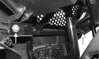
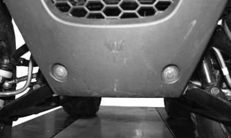
3.From the front of the vehicle, remove the two cap screws securing the lower portion of the fascia to the front bumper.
XA070
4.From within the front body panel, remove the remaining five cap screws securing the front fascia to the front body panel. Remove the fascia.
XA083A
CLEANING AND INSPECTING 1.Clean the fascia and related components with soap and water.
2.Inspect the fascia and fenders for cracks. 3.Inspect threaded areas of all mounting studs for stripping. 4.Inspect for missing decals.
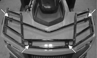
INSTALLING 1.Place the front fascia into the front body panel and secure it using the five cap screws in the locations shown. From the front of the fascia, install and secure the two lower cap screws connecting to the bumper.
XA083A
2.Install both headlights assemblies; then connect each connector to the main wire harness connectors.
Secure each connector to the frame.
XA082A
XA072
Rear Rack/Body Panel/Fender
REMOVING 1.Remove the seat, steering post cover, gas tank cover, battery, and both left and right footwells. NOTE: When disconnecting the battery, disconnect
the negative cable first, then the positive cable.
2.Disconnect the green ground wire (A) and starter relay primary connector (B). Remove the SIG relay (C) and starter relay from the rear body panel. Using a flat blade screwdriver, lightly pry against the PDM locking tab (D) to release the PDM from the rear body panel.
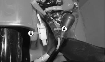
XA076A
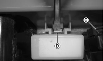
XA078A
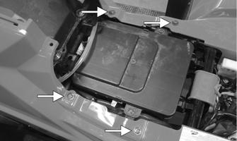
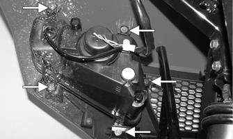
3.Remove the six cap screws securing the front body panel to the frame and gas tank. Pull the front body panel out and away from the frame.

XA077A
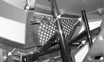
4.Remove the self-tapping screws securing the rear over-mold to the rear rack; then remove the four cap screws securing the rear rack to the frame. Remove the rack. Account for the four steel inserts installed into each rubber grommet.

XA080A

XA081A
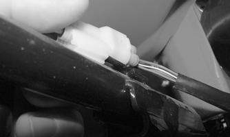
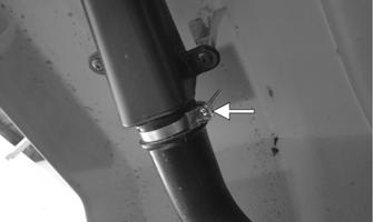
5.Located under the left rear fender, loosen the clamp securing the two halves of the CVT outlet pipe. Disconnect the two halves.
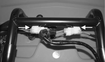
6.Using a flat blade screwdriver, release the connector locking tabs; then disconnect the tail light/brake light connectors.
XA084A
7.Remove the four cap screws securing each tail light/brake light assembly to the rear body panel assembly. Remove the tail light/brake light assemblies.
XA085A
8.Remove the rear body panel assembly.
CLEANING AND INSPECTING 1.Clean all body components with soap and water. 2.Inspect the body and fenders for cracks. 3.Inspect threaded areas of all mounting studs for stripping. 4.Inspect for missing decals.
INSTALLING 1.Place the rear body panel into position on the frame while guiding the SIG relay, starter relay, and PDM through the front of the body panel. Secure the two halves of the CVT outlet tubes together with the clamp. 2.With the four steel inserts installed into each rubber grommet, place the rear rack into position and secure with the four cap screws. 3.Place the rear over-mold atop the rear rack and secure it using the self-tapping screws.
XA080A
4.Install the six cap screws securing the front body panel to the frame, gas tank, and rear body panel; then install and secure the gas tank cover and steering post covers using the plastic reinstallable rivets.
XA077A
5.Place the PDM, SIG relay, and starter relay into their respective positions within the battery tray. Ensure the PDM locks into place. Connect the starter relay primary connector (B) and green ground wire connector (A).
XA076A
6.Place each tail light/brake light assembly into place and secure with the cap screws. Connect each wire connector to the main harness; then secure to the frame.
XA085A
XA084A
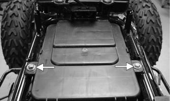
7.Install and secure both footwells. Place the battery into the tray and secure it with the battery bracket.
Connect the battery cables. Install the seat. NOTE: When connecting the battery cables, con-
nect the positive cable first, then the negative cable.
Steering Post Cover/Instrument Pod
REMOVING 1.Remove the reinstallable rivet on the front of the instrument pod and the two cap screws on the rear; then lift the assembly off and disconnect the speedometer cable.
2.Remove the self-tapping screw securing the LCD gauge assembly to the instrument pod; then remove the LCD gauge. NOTE: The LCD gauge is not a serviceable compo-
nent. If any functions are incorrect or indicator lights do not illuminate, the LCD gauge must be replaced.
INSPECTING The LCD gauge is not a serviceable component. To inspect the LCD gauge, see Electrical System.
INSTALLING 1.Connect the main harness connector to the LCD gauge; then connect the ignition harness to the ignition connectors.
2. Place the instrument pod onto the mounting bracket; then secure with the reinstallable rivet and two cap screws.
Steering Post/Tie Rods
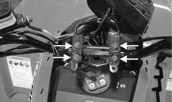
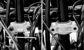
REMOVING 1.Remove the steering post cover. 2.Remove the instrument pod; then remove the cap screws securing the handlebar to the steering post.
Account for two handlebar holders.
XA075A
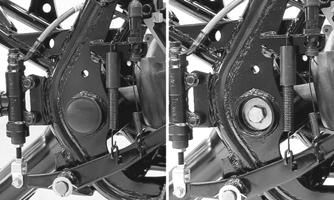
3.Lift the handlebar out of the lower handlebar holders and lay the handlebar forward. 4.Remove the cotter pins and slotted nuts securing the tie rod ends to the steering post arm; then disconnect the tie rods from the arm.
KM590
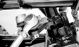
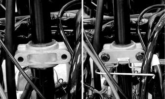
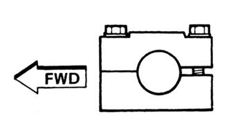
5.Remove the cotter pin and slotted nut from the lower end of the steering post; then remove the upper steering shaft support block. Account for a cable guide, two steering support blocks, and the upper steering post bushing.
KM589
6.Remove the steering post from the ATV.
CLEANING AND INSPECTING 1.Wash the tie rod ends in parts-cleaning solvent. Dry with compressed air. Inspect the pivot area for wear.
Apply a low-temperature grease to the ends.
2.Inspect the tie rods for damaged threads or wear. 3.Inspect the tie rods for cracks or unusual bends. 4.Inspect all welded areas for cracks or deterioration. 5.Inspect the steering post and steering-post holders for cracks, bends, or wear. 6.Inspect the handlebar clamps for cracks or wear. 7.Inspect the handlebar for cracks, wear, or unusual bends.
8.Inspect the handlebar grips for damage or wear. 9.Inspect the lower steering post support bearing and seal for wear or cracks.
! WARNING
Always wear safety glasses when using compressed air.
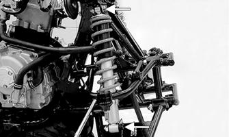
INSTALLING 1.Apply a thin coat of grease to the lips of the lower steering post seals; then lower the steering post into position in the lower steering post bearings.
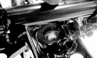
KM593
2.Apply a thin coat of grease to the upper steering post bushing; then secure the steering post with the support blocks and existing hardware. Tighten to 17 ft-lb.
KM589
KM595
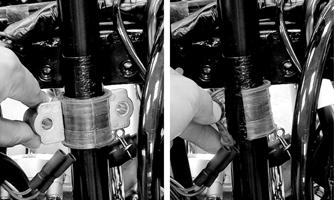
3.Install the slotted nut on the lower steering post and tighten to 50 ft-lb; then install a new cotter pin.

KM591
4.Place the inner tie rod ends into the steering post arm and tighten the slotted nuts to 15 ft-lb; then install new cotter pins.
KM590
5.Install the handlebar and tighten the clamp cap screws to 18 ft-lb making sure to tighten the front cap screws first.
KM587

KM597
6.Install the instrument pod. 7.Install the steering post cover.
Front Wheel Alignment
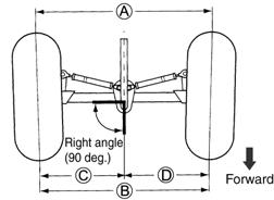
1.With the ATV on a level surface, center the handlebar for straight ahead using a suitable means of measuring centering; then adjust tire pressure to specifications (see General Information/Foreword —
Specifications). 2.Support the front of the ATV with the wheels free to rotate; then center and secure the handlebar. 3.Measure the distance (A) and (B) between the front wheels; then subtract distance (B) from (A). Distance
A - Distance B = Toe-In. 4.Adjust toe-in to 15 mm (0.60 in.); then measure distances (C) and (D). Distances (C) and (D) should be equal. 5.After all the adjustments are to specifications, tighten the tie-rod lock nuts to 15 ft-lb. NOTE: Prior to locking the jam nuts, make sure the
ball joints are at the center of their normal range of motion and at the correct angle.
NOTE: The front wheels do not have to be removed
to adjust the tie rod. Also, care should be taken not to disturb the handlebar position.
Throttle Control
REMOVING 1.Remove the boot from the throttle cable adjuster; then loosen the jam nut and turn the adjuster completely in to loosen the cable. 2.Remove the three machine screws securing the cover to the throttle control; then remove the cover and disengage the throttle cable from the throttle arm. 3.Turn the cable adjuster out of the throttle control housing; then remove the two machine screws securing the throttle control to the handlebar and remove the throttle control.
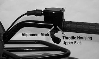
INSTALLING 1.Making sure the throttle housing upper flat aligns with the alignment mark on the handlebar, place the throttle control into position on the handlebar and secure with the two machine screws; then tighten the machine screws securely.
KM122B
2.Thread the throttle cable into the throttle housing and turn the adjuster completely in; then connect the throttle cable to the throttle arm.
3.Install the throttle housing cover; then adjust the throttle cable (see Fuel/Lubrication/Cooling —
Throttle Cable Free-Play).
Headlight — Taillight/Brake Light
Turn the ignition switch to the LIGHTS position; the headlights and taillight should illuminate. Test the brake light by compressing the brake lever. The brake light should illuminate.
NOTE: The bulb portion of the headlight is fragile.
HANDLE WITH CARE. When replacing the headlight bulb, do not touch the glass portion of the bulb. If the glass is touched, it must be cleaned with a dry cloth before installing. Skin oil residue on the bulb will shorten the life of the bulb.
! WARNING
Do not attempt to remove the bulb when it is hot. Severe burns may result.
To replace the headlight bulb, use the following procedure.
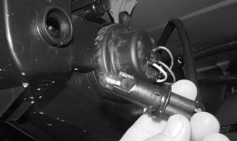
1.Remove the rubber boot from the back of the headlight housing; then remove the three-wire connector from the bulb.

XA057
2.Press forward then up on the spring clip and swing the spring clip away from the bulb; then remove the bulb from the housing.
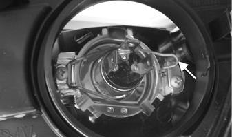
XA058A
3.Install the new bulb into the housing; then secure with the spring clip.
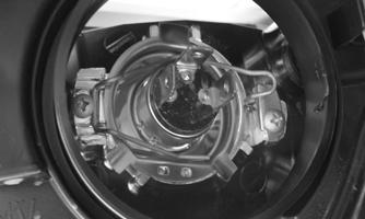
XA058
4.Connect the three-wire connector to the bulb; then install the rubber boot.
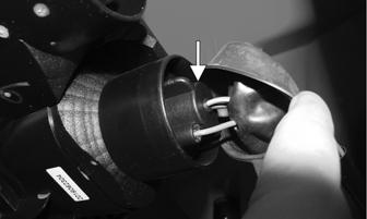
To replace the front running light bulbs, use the following procedure. Rotate the bulb socket counterclockwise to remove from the headlight housing, account for the seal. Carefully pull the bulb away from the socket.
CAUTION
When replacing the headlight bulb, be careful not to touch the glass portion of the bulb. Grasp the new bulb with a clean cloth.
XA059
To replace the taillight/brake light bulb, use the following procedure. 1.Pull the rubber boot away; then rotate the socket counterclockwise to access the bulb. Account for the seal.
XA056A
2.To remove the bulb, push the bulb in and turn it counterclockwise. 3.Install the new bulb by turning it clockwise while pushing in. 4.Insert the socket into the taillight housing; then rotate the socket clockwise to secure.
Troubleshooting
Problem: Handling too heavy or stiff Condition Remedy
1. Front wheel alignment incorrect 1.Adjust alignment 2. Lubrication inadequate 2.Lubricate appropriate components 3. Tire inflation pressure incorrect 3.Adjust pressure 4. Tie rod ends seizing 4.Replace tie rod ends 5. Linkage connections seizing 5.Repair — replace connections
Problem: Steering oscillation Condition Remedy
1. Tires inflated unequally 1.Adjust pressure 2. Wheel(s) wobbly 2.Replace wheel(s) 3. Wheel hub cap screw(s) loose — missing 3.Tighten — replace cap screws 4. Wheel hub bearing worn — damaged 4.Replace bearing 5. Tie rod ends worn — loose 5.Replace — tighten tie rod ends 6. Tires defective — incorrect 6.Replace tires 7. A-arm bushings damaged 7.Replace bushings 8. Bolts — nuts (frame) loose 8.Tighten bolts — nuts
Problem: Steering pulling to one side Condition Remedy
1. Tires inflated unequally 1.Adjust pressure 2. Front wheel alignment incorrect 2.Adjust alignment 3. Wheel hub bearings worn — broken 3.Replace bearings 4. Frame distorted 4.Repair — replace frame 5. Shock absorber defective 5.Replace shock absorber
Problem: Steering impaired Condition Remedy
1. Tire pressure too high 1.Adjust pressure 2. Steering linkage connections worn 2.Replace connections 3. Cap screws (suspension system) loose 3.Tighten cap screws
Problem: Tire wear rapid or uneven Condition Remedy
1. Wheel hub bearings worn — loose 1.Replace bearings 2. Front wheel alignment incorrect 2.Adjust alignment
Problem: Steering noise Condition Remedy
1. Cap screws — nuts loose 1.Tighten cap screws — nuts 2. Wheel hub bearings broken — damaged 2.Replace bearings 3. Lubrication inadequate 3.Lubricate appropriate components