8 minute read
Suspension

The following suspension system components should be inspected periodically to ensure proper operation: A.Shock absorber rods not bent, pitted, or damaged. B.Rubber damper not cracked, broken, or missing. C.Shock absorber body not damaged, punctured, or leaking. D.Shock absorber eyelets not broken, bent, or cracked. E.Shock absorber eyelet bushings not worn, deteriorated, cracked, or missing.
F.Shock absorber spring not broken or sagging.
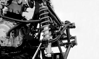
Front Shock Absorbers
REMOVING 1.Secure the ATV on a support stand to elevate the wheels and to release load on the suspension.
2.Remove the cap screws and nuts securing each shock absorber to the A-arm and frame.
! WARNING
Make sure the ATV is solidly supported on the support stand to avoid injury.
KM573A
CLEANING AND INSPECTING 1.Clean the shock absorbers in parts-cleaning solvent. 2.Inspect each shock rod for nicks, pits, bends, and oily residue. 3.Inspect the springs, spring retainers, shock rods, shock bodies, and eyelets for cracks, leaks, and bends.
INSTALLING 1.Install each shock absorber to the frame and A-arm with cap screws and nuts. Tighten all nuts to 29 ft-lb.
2.Remove the ATV from the support stand.
CAUTION
Do not tighten the nut beyond the recommended specification or the shock eyelet or mount WILL be damaged.
Rear Shock Absorber
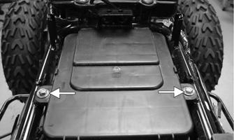
REMOVING 1.Secure the ATV on a support stand to elevate the wheels and to release load on the suspension.
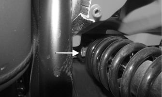
2.Remove the lower shock mounting nut and cap screw. ! WARNING
Make sure the ATV is solidly supported on the support stand to avoid injury.
XA088
NOTE: Support the swing arm with a block of wood
or other support to allow removal of the cap screw.
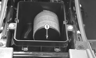
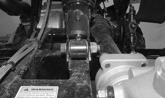
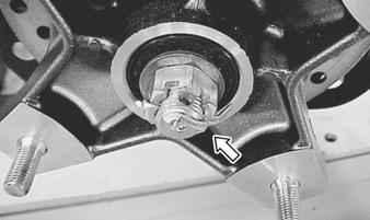
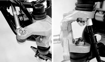
3.Remove the upper shock mounting nut and cap screw; then remove the shock absorber from the frame.
XA089A
CLEANING AND INSPECTING 1.Clean the shock absorber in parts-cleaning solvent.
2.Inspect the shock absorber body, bottom stop, and rubber bushing for damage and leaking oil. If any defects are found, replace the shock absorber. 3.Inspect the spring, spring seat, and preload adjustment collar for damage or corrosion. If corrosion or damage is present on the collar, it must be replaced.
INSTALLING 1.Raise the swing-arm and place the shock absorber in position; then install the upper and lower cap screws and nuts.
2.Tighten the upper nut and the lower nut to 29 ft-lb.
ADJUSTING SPRING PRELOAD The rear spring preload is adjustable by changing the spring set length via the ramped adjustment collar. Using the following procedure, adjust the spring. Adjust the spring preload by turning the adjuster collar (A) clockwise (when viewed from above the shock) to increase spring preload or counterclockwise to decrease spring preload.

XA090A
NOTE: To aid in adjusting preload, safely lift the
vehicle using a jack from under the frame. Lift the vehicle high enough so the wheels are no longer touching the floor.
Front A-Arms
REMOVING 1.Secure the ATV on a support stand to elevate the front wheels; then remove a front wheel.
2.Remove the hub cap; then remove the cotter pin from the nut. ! WARNING
Make sure the ATV is solidly supported on the support stand to avoid injury.
SP366
3.Remove the nut securing the hub. 4.Remove the cap screws securing the brake caliper; then remove the caliper and lay aside.
KM266A
5.Remove the hub assembly; then remove the disc cover.
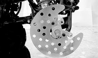
KM569
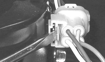
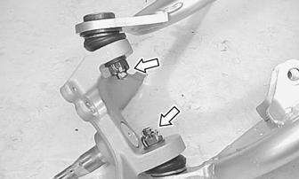
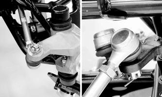
6.Remove the cotter pin and slotted nut securing the tie rod end to the knuckle; then remove the tie rod end from the knuckle.
KM573
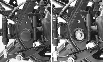
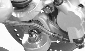
7.Remove the brake hose clamp from the A-arm; then remove the cotter pins and slotted nuts securing the upper and lower ball joints.
KM570
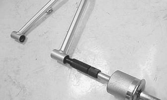
8.Remove the shock absorber mounting cap screws; then remove the shock absorber assembly. 9.Using a ball joint remover, remove the ball joints from the knuckle; then remove the front bumper.

CLEANING AND INSPECTING 1.Clean the knuckle in parts-cleaning solvent; then dry with compressed air. If any damage or excessive wear is detected, the knuckle must be replaced. 2.Inspect the ball joint for boot damage or wear.
Replace the A-arm if the ball joint is damaged or worn.
3.Inspect the arm for broken welds, cracks, or bends.
Replace if damaged. 4.Remove the bushings and dust seals and inspect for damage to seal lips and spacers. NOTE: The pivots are equipped with roller bear-
ings. The bearing rollers may fall out when the spacers are removed.
5.Check the bearings for excessive wear and replace them if worn.
6.Using a suitable bearing remover, remove the pivot bearings; then clean all parts in parts-cleaning solvent.
SP382
NOTE: All bearings, bushings, and seals that are
removed must be replaced with new ones.
INSTALLING 1.Install the bearings in the upper arm pivot to a depth of 13.6 mm (0.535 in.) with a bearing installer and suitable spacer.
ATV2196A
2.Coat the spacers and the lips of the dust seals with multi-purpose grease; then install them in the upper pivot. 3.Repeat steps 1 and 2 for the lower A-arm. 4.Clean all grease from the ball joint tapers and the knuckle bores; then install the arms to the steering knuckle and tighten the ball joint nuts to 22 ft-lb.
Install new cotter pins.

SP388A
NOTE: During assembly, new cotter pins should be
installed.
SP390
5.Install the arms to the frame with the pivot cap screws; then tighten the nuts to 32 ft-lb.

KM579
6.Install the front bumper assembly; then install the front shock absorbers. Apply red Loctite #271 on the cap screw threads and tighten to 29 ft-lb. 7.Apply red Loctite #271 to the mounting cap screws; then install the disc cover and tighten securely.
KM569
8.Connect the tie rod ends to the steering knuckle; then tighten the nut to 15 ft-lb and install a new cotter pin. NOTE: During assembly, new cotter pins should be
installed.
KM581
Wheels and Tires
TIRE SIZE
! WARNING
Use only approved tires when replacing tires. Failure to do so could result in unstable ATV operation.
The ATV is equipped with low-pressure tubeless tires of the size and type listed. Do not under any circumstances substitute tires of a different type or size. ! WARNING
Always use the size and type of tires specified. Always maintain proper tire inflation pressure.
! WARNING
Do not mix tire tread patterns. Use the same pattern type on front and rear. Failure to heed warning could cause poor handling qualities of the ATV and could cause excessive drive train damage not covered by warranty.
TIRE INFLATION PRESSURE Tire inflation pressure should be as specified.
REMOVING 1.Secure the ATV on a support stand to elevate the wheels.
2.Remove the wheels.
! WARNING
Make sure the ATV is solidly supported on the support stand to avoid injury.
NOTE: Keep left-side and right-side wheels sepa-
rated for installing them on their proper sides.
CLEANING AND INSPECTING 1.Clean the wheels and hubs with parts-cleaning solvent.
2.Clean the tires with soap and water. 3.Inspect each wheel for cracks, dents, or bends. 4.Inspect each tire for cuts, wear, missing lugs, and leaks.
NOTE: Make sure each wheel is installed on its proper hub as noted in removing (the “rotation arrow” must indicate forward direction of rotation).
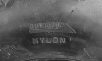
XA091
2.Tighten in a crisscross pattern to 40 ft-lb.
CHECKING/INFLATING 1.Using an air pressure gauge, measure the air pressure in each tire. Adjust the air pressure as necessary to meet the recommended inflation pressure. 2.Inspect the tires for damage, wear, or punctures. ! WARNING
Do not operate the ATV if tire damage exists.
NOTE: If repair is needed, follow the instructions
found on the tire repair kit or remove the wheel and have it repaired professionally.
NOTE: Make sure all tires are the specified size and
have identical tread pattern.
3.Check the front wheel toe-in and toe-out and adjust as necessary (see Steering/Body/Controls — Front
Wheel Alignment). 4.Test drive the ATV on a dry, level surface and note any pulling to the left or right during acceleration, deceleration, and braking. NOTE: If pulling is noted, measure the circumfer-
ence of the front and rear tires on the pulling side. Compare the measurements with the tires on the opposite side. If pulling is noted during braking only, check and adjust the brakes as necessary and recheck operation (see Periodic Maintenance/Tune-Up — Hydraulic Brake Systems).
5.Increase the air pressure in the tires with the smallest circumference measurement until all tires are equal in circumference.
6.Repeat steps 4-5 as necessary to ensure proper handling.
Troubleshooting
Problem: Suspension too soft Condition Remedy
1. Spring(s) weak 1.Replace spring(s) 2. Shock absorber damaged 2.Replace shock absorber
Problem: Suspension too stiff Condition Remedy
1. A-arm-related bushings worn or binding 1.Replace bushing
Problem: Suspension noisy Condition Remedy
1. Cap screws (suspension system) loose 1.Tighten cap screws 2. A-arm-related bushings worn 2.Replace bushings
Problem: Rear wheel oscillation Condition Remedy
1. Rear wheel hub bearings worn — loose 1.Replace bearings 2. Tires defective — incorrect 2.Replace tires 3. Wheel rim distorted 3.Replace rim 4. Wheel hub cap screws loose 4.Tighten cap screws 5. Axle shaft nut loose 5.Tighten nut 6. Auxiliary brake adjusted incorrectly 6.Adjust brake 7. Rear suspension arm-related bushing worn 7.Replace bushing 8. Rear shock absorber damaged 8.Replace shock absorber 9. Rear suspension arm nut loose 9.Tighten nut