Drive System GENERAL INFORMATION Ring Gear Backlash
0.28-0.38 mm (0.011-0.015 in.)
Ring Gear End Play
0.1-0.2 mm (0.004-0.008 in.)
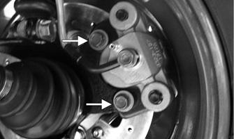
All gear cases are tagged beneath a cover bolt. This tag is marked with a production date code, sequence code, and a ratio code. The “1” or “3.1” on the lower-right corner indicates a 3.1:1 gear set ratio (11:34 teeth). SPECIAL TOOLS
KC293A
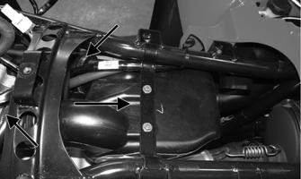
3. Remove the mounting cap screw from below the actuator on the suspension side.
A number of special tools must be available to the technician when performing service procedures in this section. Refer to the current Special Tools Catalog for the appropriate tool description. NOTE: When indicated for use, each special tool
will be identified by its specific name, as shown in the chart below, and capitalized. Description
p/n
Backlash Measuring Tool
0544-010
CV Boot Clamp Tool
0444-120
Gear Case Seal Installer Tool Kit
0444-273
Internal Hex Socket
0444-104
Pinion Gear/Shaft Removal Tool
0444-127
Slide Hammer Kit
0444-225
Multi-Seal Remover
0644-180
NOTE: Special tools are available from the Textron Off Road Service Department.
KC294A
4. Loosen but do not remove the mounting cap screw at the front of the actuator; then slide the actuator to the rear enough to clear the slotted mounting tab and the selector shaft.
Front Drive Actuator NOTE: The actuator is not a serviceable component. If it is defective, it must be replaced. NOTE: The actuator will operate only when the ignition switch is in the ON position.
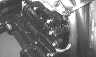
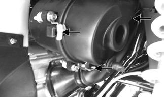
The front drive actuator is located on the side of the front drive input housing. With the engine stopped and the ignition switch in the ON position, a momentary “whirring” sound can be heard each time the front drive selector switch is shifted. If no sound is heard, see Electrical System. If the actuator runs constantly or makes squealing or grinding sounds, the actuator must be replaced. REMOVING
1. Disconnect the connector on the actuator harness. 2. Remove the mounting cap screw from the driveshaft side of the actuator.
KC295A
INSTALLING
1. Lubricate the O-ring on the actuator; then ensure that all mounting surfaces are clean and free of debris. 2. Align the actuator with the selector shaft and slide it forward onto the shaft taking care to engage the cap screw in the slot of the front mounting tab.
97