17 minute read
Steering/Body/Controls

The following steering components should be inspected periodically to ensure safe and proper operation: A.Handlebar grips not worn, broken, or loose. B.Handlebar not bent, cracked, and has equal and complete full-left and full-right turning capability. C.Steering post bearing assembly/bearing housing not broken, worn, or binding. D.Ball joints not worn, cracked, or damaged. E.Tie rods not bent or cracked.
F.Knuckles not worn, cracked, or damaged. G.Cotter pins not damaged or missing. The frame, welds, and racks should be checked periodically for damage, bends, cracks, deterioration, broken components, and missing components.
Front Rack/Body Panel/Fender
REMOVING 1.Remove the seat and both side panels. 2.Remove the front rack overmold from the rack; then remove the rack. Account for two nuts and four cap screws.
XA002 KC224
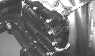
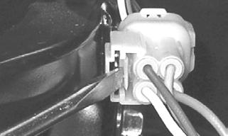
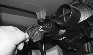
NOTE: Use a small screwdriver to disengage the tab
connector allowing the connector assembly to be removed from the frame.
KC223
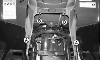
4.Remove the two push pins from the front access cover; then remove the cap screws (A) Remove the reinstallable rivets (B) and the tank cover.

XA004
XA005A
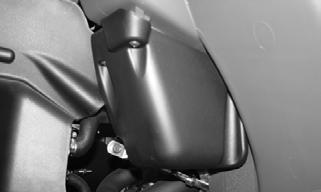
5.Remove the shift knob; then remove the shift mechanism splash shield. Remove the shift lever via the cap screw and nut. Account for spring.
XA006
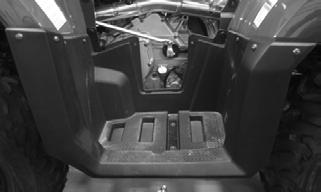
6.Remove the screws securing the front body to the front body supports.

XA007A
7.Remove the left-side and right-side footwell fasteners.
CLEANING AND INSPECTING 1.Clean all components with warm soap and water. 2.Inspect fenders for cracks. 3.Inspect for any missing decals.
INSTALLING 1.Place the front body panel/fender onto the ATV.
Making sure the shift spring is in place, the shift lever is properly positioned, and with the front rack in place, loosely install the front rack hardware. 2.Connect the light connectors and attach onto the frame.
KC224
3.Install the screws securing the front body to the front body supports.
XA007A
4.Install the left-side and right-side footwell fasteners.
Do not tighten at this time. 5.Place the gas tank cover and front access panel into position and secure with the existing hardware; then install the two cap screws securing the rear of the panel to the frame. Tighten all cap screws and fasteners securely. 6.Install the side panels and seat.
Rear Rack/Body Panel
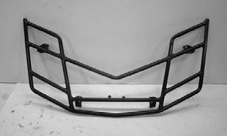
REMOVING 1.Remove the machine screws securing the rear rack overmold to the rear rack; then remove the cap screws securing the rear rack to the frame and frame brackets. Remove the rack.

XA009

XA010
2.Remove two cap screws securing the rear body panel/fender to the side frame and the cap screws securing the rear fenders to the footwells.
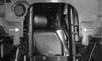
XA011A

XA012
3.Disconnect the battery (negative cable first) and remove from the battery compartment; then disconnect the starter relay wires and route the wiring out of the compartment.
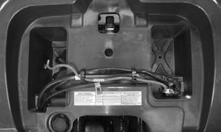
XA013
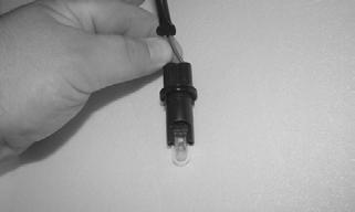
4.Using a small screwdriver, remove the light connectors from the frame; then disconnect both connectors and remove the rear body panel/fender.
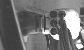
KC281

KC279
CLEANING AND INSPECTING 1.Clean all rear body panel components with warm soap and water. 2.Inspect side panels and rear body panel for cracks. 3.Inspect threaded areas of all mounting bosses for stripping. 4.Inspect for missing decals.
INSTALLING 1.Place the rear body panel/fender in place on the
ATV; then secure with the cap screws on the side frame and the rear rack assembly. Fasten the rear rack overmold to the rear rack. Tighten all fasteners securely.
XA011A

XA014
2.Connect the light connectors and secure to the frame; then install the battery and starter relay. Connect all wiring making sure to connect the positive cables first.
KC279
3.Secure the rear fenders to the footwells and tighten the nuts securely. 4.Install the seat.
Steering Post/Tie Rods
REMOVING 1.Remove the front body panel and left-side fender well.
XA015
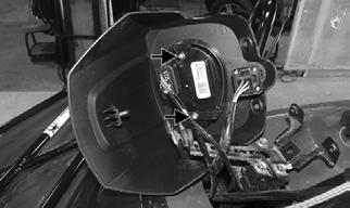
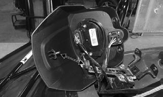
2.Remove the front access panel and release the nylon cable ties securing the PDM. 3.Remove the steering post cover; then remove the cap screws securing the handlebar caps and move the handlebar out of the way. Account for the two handlebar caps.

XA016
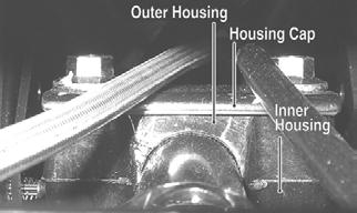
4.Remove the cap screws securing the upper steering post to the frame. Account for the housing cap, outer housing, and inner housing.
KC307A
5.Remove the cotter pins from the inner tie rod ends; then remove the nuts and disconnect the inner tie rod ends.

KC184A
NOTE: If tie rods are to be completely removed,
remove the outer tie rod ends from the knuckles at this time.
6.Remove the cap screw securing the lower steering post to the bearing. Account for a flat washer.

KC184B
7.Remove the steering post from the ATV.
CLEANING AND INSPECTING 1.Wash the tie rod ends in parts-cleaning solvent. Dry with compressed air. Inspect the pivot area for wear.
Apply a low-temperature grease to the ends.
2.Inspect the tie rods for damaged threads or wear. 3.Inspect the tie rods for cracks or unusual bends. 4.Inspect all welded areas for cracks or deterioration. 5.Inspect the steering post and steering-post brackets for cracks, bends, or wear. 6.Inspect the bearing halves, bearing caps, and bearing housings for cracks or wear. 7.Inspect the handlebar tube for cracks, wear, or unusual bends.
8.Inspect the handlebar grips for damage or wear.
! WARNING
Always wear safety glasses when using compressed air.
INSTALLING 1.Install the steering post into the frame and secure the lower end in the bearing with a flat washer and cap screw. Tighten to 40 ft-lb.
KC184B
2.Apply grease to the inner and outer housings of the upper steering post support; then with the housing cap in place, secure with the cap screws. Tighten to 20 ft-lb.
KC307A
3.Using red Loctite #271 on the threads, install the tie rod ends into the lower steering post arm and tighten to 30 ft-lb; then install new cotter pins.
KC184A
4.Place the handlebar and caps in place on the steering post and with the handlebar correctly positioned, tighten the cap screws to 20 ft-lb.
XA016
5.Install the steering post cover; then install the left-side fender well and front access panel.
LCD Gauge
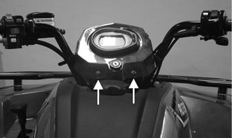
REPLACING 1.Remove the two screws securing the instrument pod to the pod mounting bracket.
XA017A
2.Unplug the gauge from the wiring harness; then remove the nuts and bracket securing the gauge to the instrument pod.

KC516A KC516B
3.Install the new gauge and mounting bracket; then connect the wiring harness to the gauge. 4. Put the instrument pod into position making sure the rear tab is in position first; then install the screws on the front.
KC516C
Handlebar Grip
REMOVING 1.Loosen but do not remove the cap screw in the end of the handlebar; then tap lightly on the head to dislodge the handlebar plug.
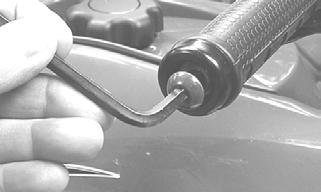
KC310

KC309A
2.Grasp the end and remove the cap screw, plug, and end cap.
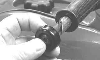
KC308
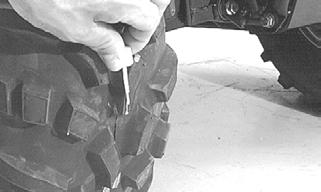
3.Using a sharp utility knife, split the handlebar grip from end to end and peel off the rubber. 4.Using an adhesive solvent, clean all glue residue from the handlebar.
INSTALLING 1.Apply a liberal amount of Handlebar Grip Adhesive to the inside of the new grip. 2.Slide the grip onto the handlebar until it is fully seated with the smooth part of the grip facing up. NOTE: A quick, firm push is required to seat the
grip completely on the handlebar. Install while the glue is wet.
3.Wipe off any excess glue; then secure the grip with the plug, end cap, and cap screw.
Throttle Control
REMOVING 1.Remove the two machine screws securing the throttle control to the handlebar.
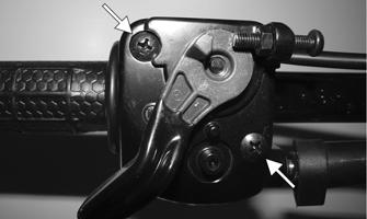
XA041A
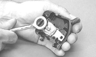
2.Slide the grommet out of the lower half of the throttle control; then remove the cable from the actuator arm.

AF676D
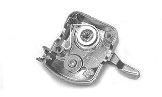
3.Remove the cap screw, lock washer, and washer securing the actuator arm to the throttle control lever.
AF677D
4.Remove the actuator arm and account for a bushing.
Note the position of the return spring for installing purposes.
AF678D
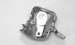
INSTALLING 1.Place the return spring into the throttle control; then place the bushing and actuator arm into position.
Secure with the cap screw, lock washer, and washer.
AF679D
2.Using a pair of needle-nose pliers, place the spring into position on the actuator arm.

AF680D
3.Place the two halves of the throttle control onto the handlebar and secure with the two machine screws.
ADJUSTING To adjust throttle cable free-play, see Fuel/Lubrication/Cooling.
Steering Knuckles
REMOVING AND DISASSEMBLING 1.Secure the ATV on a support stand to elevate the wheel; then remove the wheel.
2.Remove the wheel cap from the hub; then remove the cotter pin from the nut. 3.Remove the nut securing the hub. 4.Remove the brake caliper. 5.Remove the hub assembly. 6.Remove the cotter pin from the tie rod end and remove the tie rod end from the knuckle.
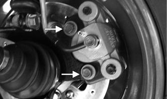
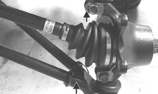
7.Remove the two cap screws securing the ball joints in the knuckle.
8.Tap the ball joint end out of the knuckle; then remove the knuckle.
9.Remove the snap ring from the knuckle; then remove the bearing. ! WARNING
Make sure the ATV is solidly supported on the support stand to avoid injury.

PR287A

PR288
CAUTION
Use extreme care when removing the bearing. If the bearing is allowed to fall, it will be damaged and will have to be replaced.
CLEANING AND INSPECTING 1.Clean all knuckle components. 2.Inspect the bearing for pits, gouges, rusting, or premature wear.
3.Inspect the knuckle for cracks, breaks, or porosity. 4.Inspect threads for stripping or damage.
ASSEMBLING AND INSTALLING 1.Install the bearing; then install the snap ring making sure it seats into the knuckle.
PR287A
2.Install the knuckle to the upper and lower ball joints and secure with the two cap screws. Tighten to 35 ft-lb.
KC313A
3.Install the tie rod end and secure with the nut.
Tighten to 30 ft-lb; then install a new cotter pin and spread the pin. NOTE: During assembling, new cotter pins should
be installed.
4.Apply a small amount of grease to the hub splines. 5.Install the hub assembly onto the splines of the shaft. 6.Secure the hub assembly with the nut. Tighten only until snug.
KC305
7.Secure the brake caliper to the knuckle with the
“patch-lock” cap screws. Tighten to 20 ft-lb.

KC283
8.Pump the hand brake lever; then engage the brake lever lock.
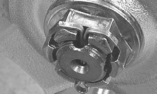
9.Secure the hub nut (from step 6) to the shaft. Tighten to 200 ft-lb.
10.Install a new cotter pin and spread the pin to secure the nut.
11.Install the wheel; then using a crisscross pattern, tighten the wheel nuts in 20 ft-lb increments to a final torque of 40 ft-lb (steel wheel), 60 ft-lb (aluminum wheel w/black nuts), or 80 ft-lb (aluminum wheel w/chrome nuts). 12.Remove the ATV from the support stand.
Front Wheel Alignment
1.Thoroughly wash the ATV to remove excess weight (mud, etc.). 2.Refer to the specifications and ensure the tires are properly inflated to the recommended pressure. NOTE: Ensure the inflation pressure is correct in
the tires or inaccurate measurements can occur.
3.Place the ATV in a level position taking care not to push down or lift up on the front end; then turn the handlebar to the straight ahead position. NOTE: When measuring and adjusting, there
should be a normal operating load on the ATV (without an operator but with approved accessories).
4.Measure the distance from the outside edge of each handlebar grip to equal reference points on each side. 5.Adjust the handlebar direction until the two measurements are equal; then secure the handlebar. NOTE: Care must be taken not to allow the handle-
bar to turn while securing it.
NOTE: The front wheels do not have to be removed
to adjust the tie rod. Also, care should be taken not to disturb the handlebar position.
6.Using a permanent marker of some type, mark the center of each front tire (at a height parallel to the belly panel).
AF789D
7.Measure the distance between the marks (at a height parallel to the belly panel) at the front side; then record the measurement.
8.Push the ATV forward until the marks are parallel to the belly panel on the back side; then measure the distance between the marks.
9.The difference in the measurements must show 1/8-1/4 in. toe-out (the front measurement 1/8-1/4 in. more than the rear measurement). 10.If the difference in the measurements is not within specifications, adjust both tie rods equally until within specifications. NOTE: Prior to locking the jam nuts, make sure the
ball joints are at the center of their normal range of motion and at the correct angle.
733-559A
Exhaust System
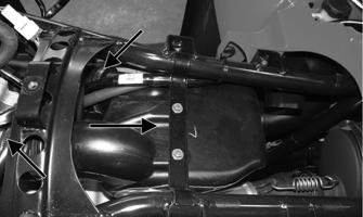
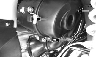
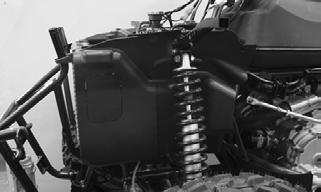
REMOVING MUFFLER 1.Remove the two exhaust springs at the muffler/exhaust pipe juncture.

KC170
2.Slide the muffler rearward to clear the mounting lugs and remove the muffler. Account for a grafoil seal.
INSPECTING MUFFLER 1.Inspect muffler externally for cracks, holes, and dents.
2.Inspect the muffler internally by shaking the muffler back and forth and listening for rattles or loose debris inside the muffler.
NOTE: For additional details on cleaning the muf-
fler/spark arrester, see Periodic Maintenance/Tune-Up.
INSTALLING MUFFLER 1.Using a new grafoil seal, place the muffler into position engaging the mounting lugs into the grommets; then slide the muffler forward.
2.Install the two exhaust springs.
Seat
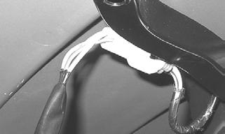
REMOVING/INSTALLING 1.To remove the seat, lift up on the latch release (located at the rear of the seat). Raise the rear of the seat and slide it rearward.
2.To lock the seat into position, slide the front of the seat into the seat retainers and push down firmly on the rear of the seat. The seat should automatically lock into position.
Lights
Rotate the ignition switch to the lights position; the headlights and taillights should illuminate. Test the brake lights by compressing the brake lever. The brake lights should illuminate.
HEADLIGHTS NOTE: The bulb portion of a headlight is fragile.
HANDLE WITH CARE. When replacing a headlight bulb, do not touch the glass portion of the bulb. If the glass is touched, it must be cleaned with a dry cloth before installing. Skin oil residue on the bulb will shorten the life of the bulb.
! WARNING
Do not attempt to remove a bulb when it is hot. Severe burns may result.
To replace the headlight bulb, use the following procedure.
1.Remove the protective rubber boot from the rear of the headlight housing; then remove the wiring harness connector from the back of the headlight bulb.

XA018

KC162
2.Press in and release the spring retainer and pull rearward clear of the bulb assembly.

KC163A
3.Remove the headlight bulb assembly from the headlight housing. 4.Install the new headlight bulb into the headlight housing being careful not to get fingerprints or other contaminates on the glass; then secure with the spring.

KC163B
5.Connect the wiring harness connector to the bulb; then install the protective rubber boot making sure it seals completely on the headlight harness.
XA018
TAILLIGHTS-BRAKE LIGHTS To replace a taillight-brake light bulb, use the following procedure. 1.Remove the protective rubber boot; then turn the bulb socket assembly counterclockwise and remove from the housing.
XA019
2.Press in and turn the bulb counterclockwise to remove. Press in and turn clockwise to install the bulb.
3.Insert the bulb socket assembly into the housing and turn it clockwise to secure. Install the rubber boot.
RUNNING LIGHTS The running lights are located outboard of the headlights. To replace the bulbs, use the following procedure. 1.Rotate the bulb socket counterclockwise; then pull the bulb from the socket.

XA018B
XA032
2.Push a new bulb into the socket; then place the socket into the light housing and turn clockwise to secure.
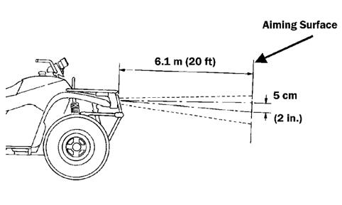
CHECKING/ADJUSTING HEADLIGHT AIM The headlights can be adjusted vertically and horizontally. The geometric center of the HIGH beam light zone is to be used for vertical and horizontal aiming. 1.Position the ATV on a level floor so the headlights are approximately 6.1 m (20 ft) from an aiming surface (wall or similar aiming surface).

ATV-0070C
NOTE: There should be an average operating load
on the ATV when adjusting the headlight aim.
2.Measure the distance from the floor to the mid-point of each headlight. 3.Using the measurements obtained in step 2, make horizontal marks on the aiming surface. 4.Make vertical marks which intersect the horizontal marks on the aiming surface directly in front of the headlights. 5.Switch on the lights. Make sure the HIGH beam is on. DO NOT USE LOW BEAM.
6.Observe each headlight beam aim. Proper aim is when the most intense beam is centered on the vertical mark 5 cm (2 in.) below the horizontal mark on the aiming surface. 7.Adjust each headlight by turning the adjuster screw clockwise to raise the beam or counterclockwise to lower the beam.
KC406A
Troubleshooting
Problem: Handling too heavy or stiff Condition Remedy
1. Front wheel alignment incorrect 1.Adjust alignment 2. Lubrication inadequate 2.Lubricate steering shaft 3. Tire inflation pressure low 3.Adjust pressure 4. Tie rod ends seizing 4.Replace tie rod ends 5. Linkage connections seizing 5.Repair — replace connections
Problem: Steering oscillation Condition Remedy
1. Tires inflated unequally 1.Adjust pressure 2. Wheel(s) bent 2.Replace wheel(s) 3. Wheel lug nut(s)/wheel stud(s) loose — missing 3.Tighten — replace lug nuts/wheel studs 4. Wheel hub bearing worn — damaged 4.Replace bearing 5. Tie rod ends worn — loose 5.Replace — tighten tie rod ends 6. Tires defective — incorrect 6.Replace tires 7. A-arm bushings damaged 7.Replace bushings 8. Bolts — nuts (frame) loose 8.Tighten bolts — nuts
Problem: Steering pulling to one side Condition Remedy
1. Tires inflated unequally 1.Adjust pressure 2. Front wheel alignment incorrect 2.Adjust alignment 3. Wheel hub bearings worn — broken 3.Replace bearings 4. Frame distorted 4.Repair — replace frame 5. Shock absorber defective 5.Replace shock absorber
Problem: Tire wear rapid or uneven Condition Remedy
1. Wheel hub bearings worn — loose 1.Replace bearings 2. Front wheel alignment incorrect 2.Adjust alignment 3. Tire inflation pressure incorrect 3.Adjust pressure
Problem: Steering noise Condition Remedy
1. Cap screws — nuts loose 1.Tighten cap screws — nuts 2. Wheel hub bearings broken — damaged 2.Replace bearings 3. Lubrication inadequate 3.Lubricate appropriate components