Drive and Brake Systems GENERAL INFORMATION
The die-cast aluminum housings have been assembled with thread-rolling screws (trilobular). When assembling with these screws, start the screws carefully into the housing; then use the following torque values. Size
New Housing
Reassembled Housing
M6 (Torx T-30 Recess) 9 ft-lb
8 ft-lb
M8 (Torx T-40 Recess) 28 ft-lb
23 ft-lb
WC938A
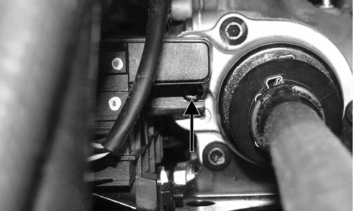
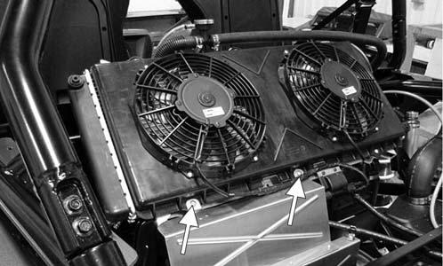
3. Remove the mounting cap screw from below the actuator on the suspension side.
SPECIAL TOOLS
A number of special tools must be available to the technician when performing service procedures in this section. Refer to the current Special Tools Catalog for the appropriate tool description. NOTE: When indicated for use, each special tool
will be identified by its specific name, as shown in the chart below, and capitalized. Description Backlash Measuring Tool (24-Spline Axle)
p/n 0544-010
Backlash Measuring Tool (27-Spline Axle)
0544-011
CV Boot Clamp Tool
0444-120
Hose Clamp Pliers
0644-545
Hub Retaining Wrench
0444-270
Internal Hex Socket
0444-104
Pinion Gear/Shaft Removal Tool
0444-127
Gear Case Seal Installer Tool
0444-273
WC940A
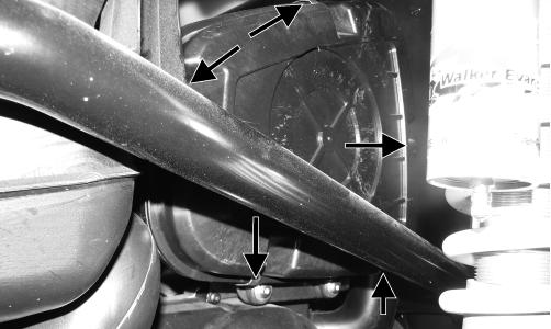
4. Loosen but do not remove the mounting cap screw at the front of the actuator; then slide the actuator to the rear enough to clear the slotted mounting tab and the selector shaft. Remove from the right side.
NOTE: Special tools are available from the Arctic Cat Service Department.
Front Drive Actuator NOTE: The actuator is not a serviceable component. If it is defective, it must be replaced. NOTE: The actuator will operate only when the ignition switch is in the ON position. WC939A
The front drive actuator is located on the left side of the front differential input housing. With the engine stopped and the ignition switch in the ON position, a momentary “whirring” sound can be heard each time the drive select switch is shifted. If no sound is heard, see Electrical System. If the actuator runs constantly or makes squealing or grinding sounds, the actuator must be replaced. REMOVING
1. Select LOCK on the drive select switch; then disconnect the connector on the actuator harness. 2. Using a T-30 torx wrench, remove the mounting cap screw from the driveshaft side of the actuator.
114
INSTALLING
1. Lubricate the O-rings on the actuator; then ensure all mounting surfaces are clean and free of debris. 2. Align the actuator with the selector shaft and slide it forward onto the shaft taking care to engage the cap screw in the slot of the front mounting tab. NOTE: Make sure to properly align the differential lock actuator lever with the hole in the differential lock plunger.