19 minute read
Periodic Maintenance/Tune-Up

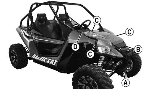
Tighten all nuts, bolts, and cap screws. Care must be taken that all calibrated nuts, bolts, and cap screws are tightened to specifications. It is advisable to lubricate certain components periodically to ensure free movement. Apply light oil to the components using the following list as reference. A.Accelerator Pedal Pivot/Cable Ends
B.Brake Pedal Pivot
C.Shift Cable
SPECIAL TOOLS A number of special tools must be available to the technician when performing service procedures in this section. Refer to the current Special Tools Catalog for the appropriate tool description. NOTE: When indicated for use, each special tool
will be identified by its specific name, as shown in the chart below, and capitalized.
NOTE: Special tools are available from the Arctic
Cat Service Department.
Description p/n
Compression Tester Kit 0444-213 Oil Filter Wrench 0644-389 Valve Clearance Adjuster 0444-255
Air Filter
CLEANING AND INSPECTING FILTER CAUTION
Failure to inspect the air filter frequently if the vehicle is used in dusty, wet, or muddy conditions can damage the engine.
1.Unsnap the five fasteners securing the air cleaner housing cover and remove the cover.
WC023A
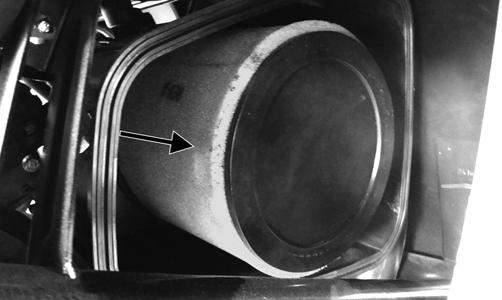
2.Remove the air filter from the housing; then remove the foam filter medium.
WC024A
3.Place each inner and outer element in a pan larger than the elements and spray both sides generously with cleaning solvent. Let sit approximately three minutes.
NOTE: Foam Filter Cleaner and Foam Filter Oil
are available from Arctic Cat.
4.In a pan larger than each element and with a mild detergent (dish soap) and water, wash all the dirt and oil off by squeezing or matting each element not twisting it (wringing out or twisting the filter can cause damage.) 5.Rinse off any remaining soap. 6.Remove any excess water from the elements by matting with a towel. 7.Allow the elements to dry completely. 8.Spray oil generously onto each air filter and work the oil into the elements.
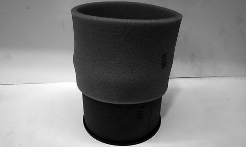
9.Squeeze each element to remove excess oil. 10.Attach the foam filter to the inner filter screen.
WC140
CAUTION
A torn air filter can cause damage to the vehicle engine. Dirt and dust may get inside the engine if the element is torn. Carefully examine the element for tears before and after cleaning it. Replace the element with a new one if it is torn.
11.Clean any dirt or debris from inside the air cleaner.
Be sure no dirt enters the throttle body.
12.Install the filter in the air filter housing. Position the filter frame on top. 13.Install the air filter housing cover and secure with the retaining clips.
CHECKING AND CLEANING DRAINS 1.Inspect the drain beneath the main housing for debris or liquid. Remove and clean the drain bulb if contaminated.
2.Wipe any accumulation of oil or gas from the filter housing and drain.
Valve/Tappet Clearance
To check and adjust valve/tappet clearance, use the following procedure. NOTE: The engine must be cold for this procedure. NOTE: On the X, the seats, left-side seat belt and
anchor, left-side heat shroud and shield, cargo box, and rear body panel must be removed for this procedure.
NOTE: On the 4X, the rear seats, left-rear seat belt
retractor, left-side heat shroud and shield, cargo box, and rear body panel must be removed for this procedure.
1.Remove the spark plugs and timing inspection plug; then remove the tappet covers (for more detailed information, see Engine/Transmission - Servicing
Top-Side Components). NOTE: Remove the crankshaft end cap and install
the special cap screw (left-hand threads) to rotate the engine.
2.Rotate the crankshaft to the TDC position on the compression stroke of the front cylinder. The stamped “F” must be visible.
GZ063
NOTE: At this point, the rocker arms and adjuster
screws must not have pressure on them.
3.Align the timing mark to the magneto cover mark.
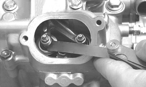
CHECKING Using a feeler gauge, check each valve/tappet clearance. If clearance is not within specifications, loosen the jam nut and rotate the tappet adjuster screw until the clearance is within specifications. Tighten each jam nut securely after completing the adjustment.
CAUTION
The feeler gauge must be positioned at the same angle as the valve and valve adjuster for an accurate measurement of clearance. Failure to measure the valve clearance accurately could cause valve component damage.
VALVE/TAPPET CLEARANCE
Intake 0.1016 mm (0.004 in.) Exhaust 0.1524 mm (0.006 in.)
CC007D
ADJUSTING A.Place the Valve Clearance Adjuster onto the jam nut securing the tappet adjuster screw; then rotate the valve adjuster dial clockwise until the end is seated in the tappet adjuster screw. B.While holding the valve adjuster dial in place, use the valve adjuster handle and loosen the jam nut; then rotate the tappet adjuster screw clockwise until friction is felt.
C.Align the valve adjuster handle with one of the marks on the valve adjuster dial. D.While holding the valve adjuster handle in place, rotate the valve adjuster dial counterclockwise until proper valve/tappet clearance is attained. NOTE: Refer to the appropriate specifications in
CHECKING for the proper valve/tappet clearance.
NOTE: Rotating the valve adjuster dial counter-
clockwise will open the valve/tappet clearance by 0.05 mm (0.002 in.) per mark.
E.While holding the adjuster dial at the proper clearance setting, tighten the jam nut securely with the valve adjuster handle.
F.Rotate engine 270° to the TDC position of the rear cylinder (the stamped “R” must be visible); then repeat steps A-E for the rear cylinder.
GZ059
4.Install the spark plugs and timing inspection plug; then remove the cap screw from the crankshaft and install the crankcase end cap. NOTE: Apply grease to the end cap to aid in instal-
lation.
5.Place the two tappet covers into position making sure the proper cap screws are with the proper cover.
Tighten the cap screws securely.
Testing Engine Compression
NOTE: The engine should be warm (operating tem-
perature) and the battery fully charged for an accurate compression test. In the event the engine cannot be run, cold values are included.
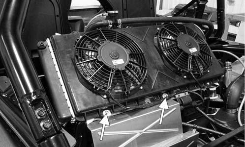
NOTE: On the X, the seats and rear body panel
must be removed and the radiator tilted rearward for this procedure.
NOTE: On the 4X, the rear seats and rear body
panel must be removed and the radiator tilted rearward for this procedure.
1.Remove the high tension lead from the spark plugs. 2.Using compressed air, blow any debris from around the spark plugs.
3.Remove the spark plugs; then attach the high tension leads to the plugs and ground the plugs on the cylinder heads well away from the spark plug holes. 4.Attach the Compression Tester Kit. 5.While holding the throttle in the full-open position, crank the engine over with the electric starter until the gauge stops climbing (five to 10 compression strokes). Compression should be 190-220 psi.
! WARNING
Always wear safety glasses when using compressed air.
NOTE: If the throttle is not held in the full-open
position, compression reading can be low.
6.If compression is abnormally low, verify the following: A.Battery is fully charged and in good health. B.Starter cranks engine over (normal speed). C.Gauge is functioning properly. D.Throttle in the full-open position. E.Valve/tappet clearance correct. F.Engine warmed up. G.Intake not restricted.
NOTE: To service top-side components, see
Engine/Transmission.
7.Pour approximately 30 ml (1 fl oz) of oil into the spark plug holes, reattach the gauge, and retest compression. 8.If compression increases to normal, service the top end (see Engine/Transmission - Servicing Top-Side
Components).
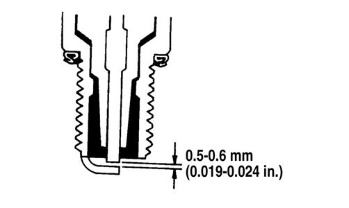
Spark Plugs
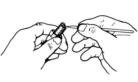
A light brown insulator indicates the plug and fuel/air ratio are correct. A white or dark insulator indicates that the engine may need to be serviced. To maintain a hot, strong spark, keep the plug free of carbon. Adjust the gap to 0.5-0.6 mm (0.019-0.024 in.).
ATV-0051
CAUTION
Before removing a spark plug, be sure to clean the area around the spark plug. Dirt could enter engine when removing or installing the spark plug.
ATV0052E
A new spark plug should be tightened 1/2 turn once the washer contacts the cylinder head. A used spark plug should be tightened 1/8-1/4 turn once the washer contacts the cylinder head.
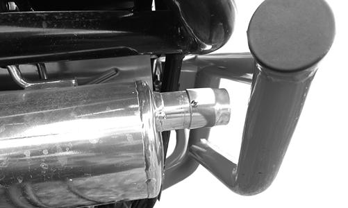
Muffler/Spark Arrester
Clean the spark arrester using the following procedure.
1.Remove the machine screw securing the spark arrester to the muffler.
! WARNING
Wait until the muffler cools to avoid burns.
WC900
2.Remove the spark arrester screen; then using a suitable brush, clean the carbon deposits from the screen taking care not to damage the screen. NOTE: If the screen is damaged in any way, it must
be replaced.
3.Install the spark arrester assembly and secure with the machine screw. Tighten the cap screw to 6 ft-lb.
Engine/Transmission Oil - Filter
OIL - FILTER Change the engine oil and oil filter at the scheduled intervals. The engine should always be warm when the oil is changed so the oil will drain easily and completely. 1.Park the vehicle on level ground. 2.Remove the oil level stick/filler plug.
! WARNING
Use caution when removing oil level stick. Exhaust components may be extremely hot.
WC895A
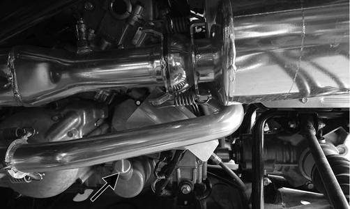
3.Remove the drain plug from the bottom of the engine and drain the oil into a drain pan. Account for and discard the gasket.
! WARNING
Use extreme caution when removing the oil drain plug. Hot oil can cause severe injury and skin burns.
PR078A
4.Using the Oil Filter Wrench and a ratchet handle (or a socket or box-end wrench), remove the old oil filter. Account for and discard the O-ring. NOTE: Clean up any excess oil after removing the
filter.
5.Apply oil to a new filter O-ring and check to make sure it is positioned correctly; then install the new oil filter. Tighten securely. 6.Install the engine drain plug with new gasket and tighten to 20 ft-lb. Pour the specified amount of the recommended oil in the filler hole. Install the oil level stick/filler plug. 7.Start the engine (while the vehicle is outside on level ground) and allow it to idle for a few minutes. 8.Turn the engine off and wait approximately one minute.
9.Unscrew the oil level stick and wipe it with a clean cloth.
10.Install the oil level stick and thread into the engine case.
NOTE: The oil level stick should be threaded into
the case for checking the oil level.
11.Remove the oil level stick; the oil level must be within the operating range but not exceeding the upper mark.
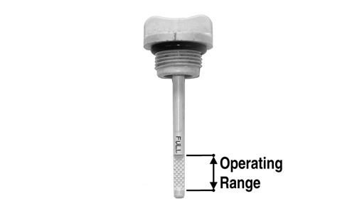
GZ461A
CAUTION
Do not over-fill the engine with oil. Always make sure that the oil level is not above the upper mark.
12.Inspect the area around the drain plug and oil filter for leaks.
Front Differential - Rear Drive Lubricant
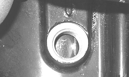
To check front differential lubricant, use the following procedure. 1.Remove the level plug; lubricant should be level with the bottom threads.
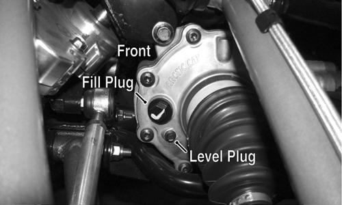
WC019A
2.If low, remove the fill plug and add SAE approved 80W-90 hypoid gear lube until it appears at the level plug threads. To check rear drive lubricant, use the following procedure.
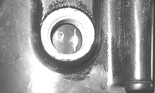
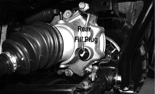
1. Remove the fill plug; the lubricant level should be level with the bottom of the plug threads.
WC020A
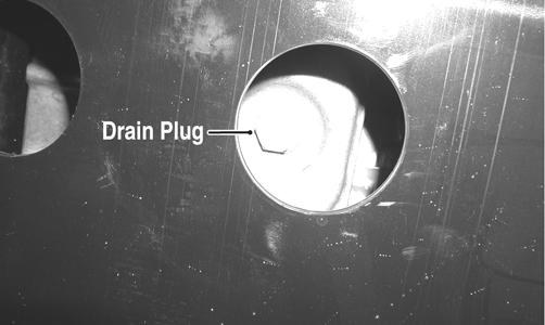
2.If low, add SAE approved 80W-90 hypoid gear lube as necessary. To change the lubricant, use the following procedure. 1.Place the vehicle on level ground. 2.Remove each fill plug. 3.Drain the lubricant into a drain pan by removing the drain plug from the gear case.
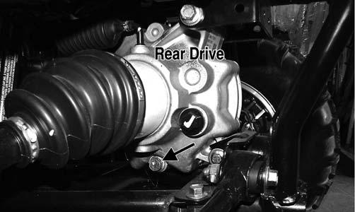
WC020B
4.After all the lubricant has been drained, install the drain plugs and tighten to 45 in.-lb. 5.Pour the appropriate amount of recommended lubricant into the fill hole.
6.Install the fill plug and tighten to 16 ft-lb. NOTE: If the lubricant is contaminated with water,
inspect the drain plug, fill plug, and/or bladder.
Driveshaft/Coupling
The following drive system components should be inspected periodically to ensure proper operation. A.Spline lateral movement (slop). B.Coupling cracked, damaged, or worn. C.Carrier bearings smooth rotation and bearing supports tight.
Headlight - Taillight/Brakelight
NOTE: The LEDs are not replaceable. The entire
assembly must be replaced as a component.
To replace the headlight assembly, use the following procedure.
1.With the hood removed, remove the wiring harness connector from the back of the headlight.
WC360B
2.Remove the three mounting screws; then remove the headlight assembly.
WC099A
2.Remove the taillight/brakelight assembly. 3.Install the new taillight/brakelight assembly and secure with new lock nuts. Tighten securely; then connect the electrical connector.
CHECKING/ADJUSTING HEADLIGHT AIM The headlights can be adjusted vertically. The geometric center of the HIGH beam light zone is to be used for vertical aiming. 1.Position the vehicle on a level floor so the headlights are approximately 6.1 m (20 ft) from an aiming surface (wall or similar aiming surface).
WC360A
3.Install the new headlight assembly and connect the wiring harness. Install the hood. 4.Adjust the headlight using the Checking/Adjusting
Headlight Aim instructions in this sub-section.
To replace the taillight/brakelight assembly, use the following procedure. 1.Disconnect the taillight/brakelight connector; then remove the lock nuts securing the assembly to the mounting bracket.
0748-171
NOTE: The tires must be properly inflated and
there should be an average operating load on the vehicle when adjusting the headlight aim.
2.Measure the distance from the floor to the mid-point of each headlight. 3.Using the measurements obtained in step 2, make horizontal marks on the aiming surface. 4.Switch on the lights. Make sure the HIGH beam is on. DO NOT USE LOW BEAM.
5.Observe each headlight beam aim. Proper aim is when the most intense beam is 5 cm (2 in.) below the horizontal mark on the aiming surface. 6.Adjust each headlight until correct aim is obtained by turning the screw with a 4 mm wrench counterclockwise to raise or clockwise to lower the beam.
WC361A
Shift Lever/Shift Cable
CHECKING Turn the ignition switch on; then shift the transmission into park. The letter P should illuminate on the LCD gauge and the park icon (P) should illuminate. The vehicle should not be able to move.
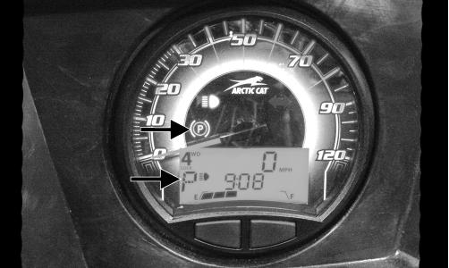
WC033A
Move the shift lever all the way forward. The letter L should illuminate on the LCD gauge.
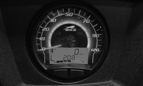
WC094
If either park or low range cannot be reached, the shift cable must be adjusted.
ADJUSTING NOTE: Shift cable adjustment should not be neces-
sary unless replacing the shift cable or shift lever.
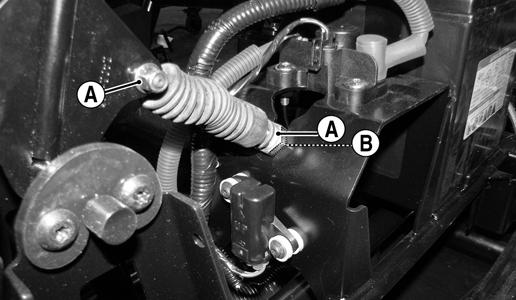
1.Remove the seats; then remove the battery cover and center console. 2.Loosen adjuster nut (A) and jam nut (B) and adjust the cable as necessary to obtain park in the full aft position of the shift lever and low range full forward.
Tighten the jam nut securely.
WC348C
Hydraulic Brake System
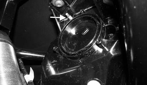
CHECKING/BLEEDING The hydraulic brake system has been filled and bled at the factory. To check and/or bleed a hydraulic brake system, use the following procedure. 1.With the master cylinder in a level position, check the fluid level in the reservoir. If the level in the reservoir is not above the MIN, add DOT 4 brake fluid.

PR095
2.Depress the brake pedal several times to check for a firm brake. If the brake is not firm, the system must be bled.
3.To bleed the brake system, use the following procedure:
A.Remove the cover and fill the reservoir with DOT 4 brake fluid.
B.Install and secure the cover; then slowly press the brake pedal several times. C.Install one end of a clear hose onto the bleed screw farthest from the cylinder (right rear) and direct the other end into a container; then while holding slight pressure on the brake pedal, open the bleed screw and watch for air bubbles. Close the bleed screw before releasing the brake pedal. Repeat this procedure until no air bubbles are present.
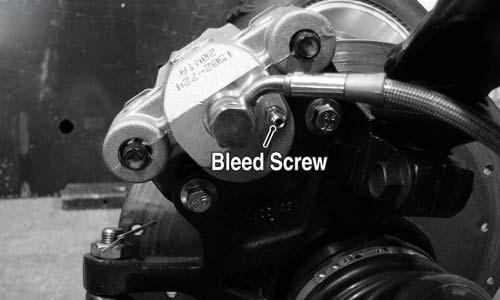
WC268B
NOTE: During the bleeding procedure, watch the
reservoir very closely to make sure there is always a sufficient amount of brake fluid. If the fluid level gets low in the reservoir, refill the reservoir before the bleeding procedure is continued.
D.Repeat step C until the brake pedal is firm. E.At this point, perform step B, C, and D on the left rear bleed screw; then move to the right front bleed screw and follow the same procedure. Finish with the left front bleed screw.
4.Carefully check the entire hydraulic brake system to ensure all hose connections are tight, the bleed screws are tight, the protective caps are installed, and no leakage is present.
CAUTION
This hydraulic brake system is designed to use DOT 4 brake fluid only. If brake fluid must be added, care must be taken as brake fluid is very corrosive to painted surfaces.
INSPECTING HOSES Carefully inspect the hydraulic brake hoses for cracks or other damage. If found, the brake hoses must be replaced.
CHECKING/REPLACING PADS The clearance between the brake pads and brake discs is adjusted automatically as the brake pads wear. The only maintenance that is required is replacement of the brake pads when they show excessive wear. Check the thickness of each of the brake pads as follows. 1.Remove a wheel.
2.Measure the thickness of each brake pad. 3.If thickness of either brake pad is less than 1.0 mm (0.039 in.), the brake pads must be replaced. NOTE: The brake pads should be replaced as a set. 4.To replace the rear brake pads, use the following procedure.
A.Remove the cap screws securing the caliper holder to the knuckle; then remove the pads from the caliper.
PR237
B.Install the new brake pads. C.Secure the caliper holder to the knuckle with new
“patch-lock” cap screws. Tighten to 20 ft-lb.
WC268A
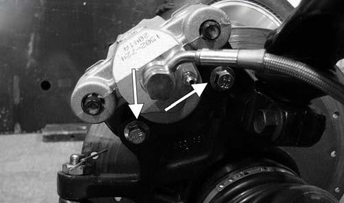
5.To replace the front brake pads, use the following procedure. A.Remove the E-clips from the inboard end of the caliper anchor bolts; then remove the anchor bolts from the knuckle.

WC611A
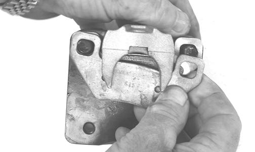
B.Remove the caliper and pads from the vehicle.
WC610
NOTE: It will be necessary to retract the pistons to
accommodate new pads. It may be necessary to open the bleed screw slightly.
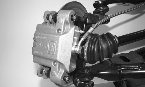
C.Install the new brake pads; then secure the caliper and pads to the knuckle with the anchor bolts.
Tighten to 35 ft-lb and install the E-clips.
6. Install the wheels and using a crisscross pattern, tighten the wheel nuts in 20 ft-lb increments to a final torque of 40 ft-lb (steel wheel), 60 ft-lb (aluminum wheel w/black nuts), or 80 ft-lb (aluminum wheel w/chrome nuts). 7.Burnish the brake pads (see Burnishing Brake Pads).
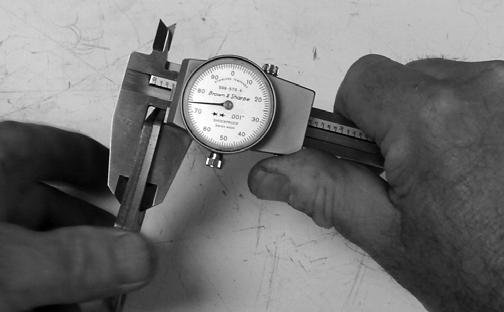
BRAKE DISC Using a micrometer, measure the thickness of the brake disc in multiple contact surfaces. If thickness is 0.125-in. or less, the disc must be replaced. To replace the brake disc, see Drive and Brake Systems – Hub.
Burnishing Brake Pads
Brake pads must be burnished to achieve full braking effectiveness. Braking distance will be extended until brake pads are properly burnished. To properly burnish the brake pads, use the following procedure.
1.Choose an area large enough to safely accelerate the vehicle to 30 mph and to brake to a stop. 2.Accelerate to 30 mph; then release the accelerator pedal and depress the brake pedal to decelerate to 0-5 mph. 3.Repeat procedure 20 times until brake pads are burnished. ! WARNING
Failure to properly burnish the brake pads could lead to premature brake pad wear or brake loss. Brake loss can result in severe injury.
Replacing V-Belt
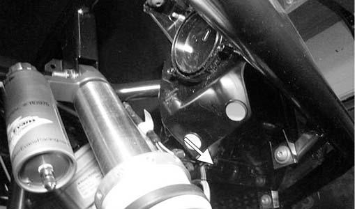
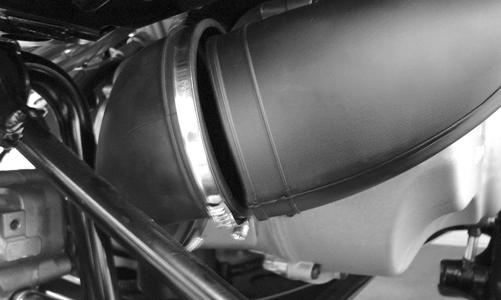
REMOVING 1.Raise the rear of the vehicle just enough to unload the rear suspension (weight off the shock absorbers). 2.Remove the right rear shock absorber; then loosen the clamp securing the cooling exhaust duct to the boot.
WC599
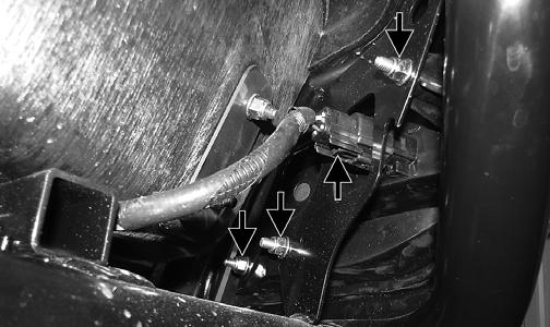
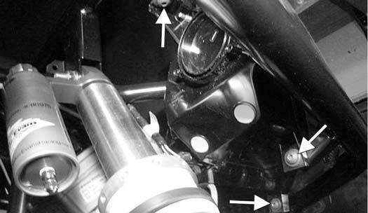
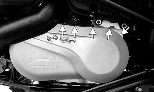
3.Remove the cap screws securing the CVT cover,
CVT exhaust pipe mount, and air filter bracket. Note the longer cap screws securing the exhaust cooling duct bracket and air filter housing bracket.
WC620A
4.Remove the CVT cover. Account for two alignment pins. 5.Remove the cap screw securing the driven clutch to the transmission input shaft. Account for the washer and alignment shim(s).
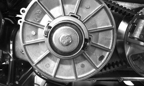
WC597
WC810
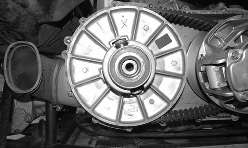
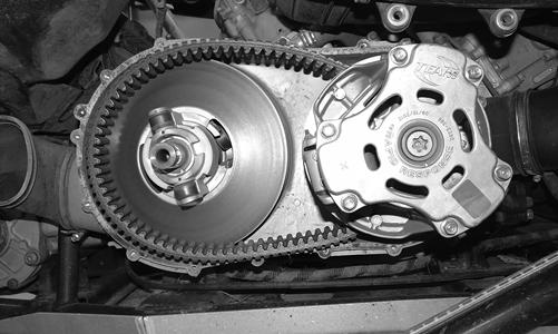
6.Remove the movable sheave and V-belt and any belt threads or debris in the CVT housing or sheaves.
WC809
NOTE: If threads are fouling the drive clutch, it may be
necessary to remove the clutch and disassemble it to free threads from the center bearing (see Engine/Transmission - Removing Right-Side Components).
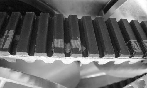
CHECKING Use the Drive Belt Gauge to identify any abnormal wear. Measure across the top of the V-belt (in multiple locations) using a Vernier caliper. Do not squeeze the belt as doing so may produce an inaccurate measurement. The V-belt must be at least 28.5 mm at any point.
INSTALLING NOTE: If any drive clutch or driven clutch compo-
nent has been replaced or the technician is unsure of shim quantity/placement, clutch offset must be verified (see Engine/Transmission - Installing Right-Side Components steps 10-13).
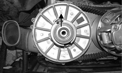
1.Making sure the directional arrow on the belt is aligned with engine rotation, place the new drive belt in place on the drive clutch; then making sure the
“X” marks are aligned, install the movable sheave on the driven clutch.
WC667
WC810A
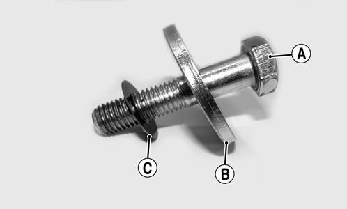
2.Secure the driven clutch with the cap screw (A), washer (B), and alignment shim(s) (C); then tighten to 60 ft-lb.
WC741A
3.Place the alignment pins and new gasket on the clutch housing; then install the CVT cover, CVT exhaust pipe mount, and air filter bracket and secure with the cap screws. Tighten in a crisscross pattern to 8 ft-lb. 4.Connect the exhaust duct and tighten the boot clamp securely. 5.Install the rear shock absorber and secure with the cap screws. Tighten the upper cap screw to 40 ft-lb and the lower cap screw to 35 ft-lb. NOTE: Drive belts require a break-in period (see
Drive Belt Break-In Procedure in the General Information Section).
CAUTION