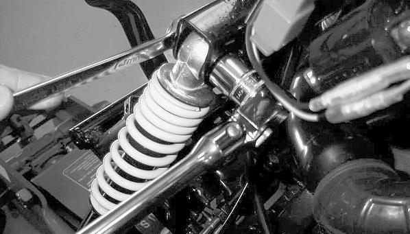
Steering/Body/Controls The following steering components should be inspected periodically to ensure safe and proper operation. A. Handlebar grips worn, broken, or loose. B. Handlebar bent, cracked, and an equal and complete full-left and full-right turn capability. C. Steering post bearing assembly/bearing housing broken, worn, or binding. D. Ball joints worn, cracked, or damaged. E. Tie rods bent or cracked. F. Knuckles worn, cracked, or damaged. G. Cotter pins damaged or missing. The frame and welds should be checked periodically for damage, bends, cracks, deterioration, broken components, and missing components.
YT224
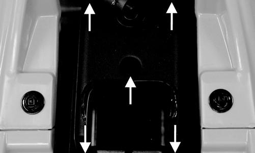
4. Remove both left and right footwells by removing the Phillips-head screws and cap screws. 5. On the 90 Utility, remove both front and rear racks. Note the spacers installed in the rubber grommets of the main body panel. 6. Remove the two cap screws and plastic push pin securing the handlebar pod to the bracket.
Body REMOVING
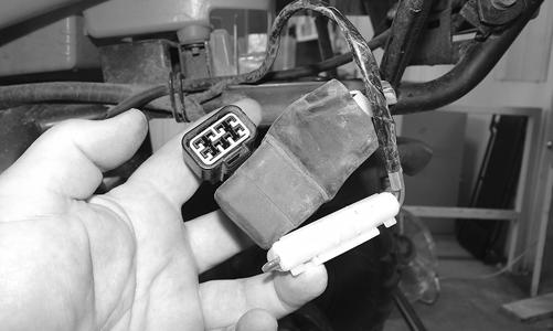
1. Remove the seat and battery bracket; then disconnect the battery and remove it from the vehicle. 2. Disconnect the CDI unit; then pull the CDI connector, main relay, and main fuse case through the main body panel. YT225A
7. Disconnect the one 4-pin connector and two 2-pin connectors from the pod and remove from vehicle. 8. Disconnect both brakelight switches and handlebar switch connectors. 9. Remove the two Allen-head cap screws from the hydraulic hand brake assembly.
YT223
3. Disconnect both left and right headlight connectors.
KM208A
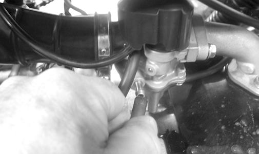
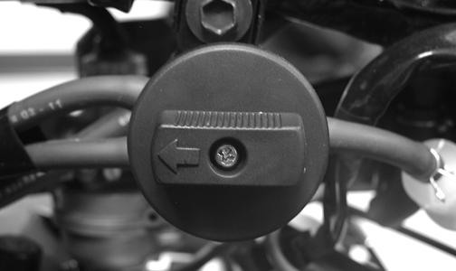
10. Remove the two Phillips-head cap screws securing the throttle cable cover to the housing; then remove the throttle cable. 11. Remove both brake cables from the right side of the handlebar. Match-mark both cable locations. 15