37 minute read
Engine/Transmission

This section has been organized into sub-sections which show a progression for the complete servicing of the Arctic Cat Y-12+ engine/transmission. NOTE: Arctic Cat recommends the use of new gas-
kets, lock nuts, and seals and lubricating all internal components when servicing the engine/transmission.
NOTE: A new ATV and an overhauled ATV engine
require a “break-in” period. The first 10 hours (or 200 miles) are most critical to the life of this ATV. Proper operation during this break-in period will help assure maximum life and performance from the ATV. Instruct the customer to follow the proper break-in procedure as described in the Operators Manual.
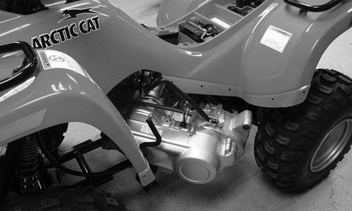
Removing Engine/ Transmission
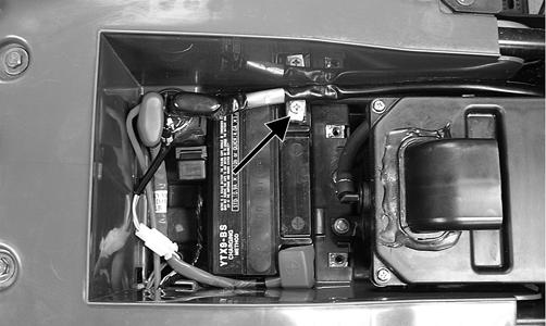
1.Turn the gas tank valve to the OFF position; then remove the seat and disconnect the negative battery cable securing it away from the battery.
CD643
! WARNING
Battery acid is harmful if it contacts eyes, skin, or clothing. Care must be taken whenever handling a battery.
KM853A
2.Drain the transmission lubricant.

YT215A
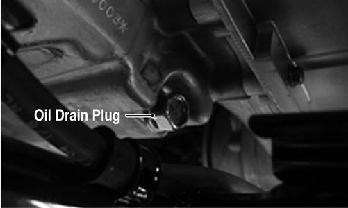
3.Drain the engine oil. NOTE: The drain plug is located at the left-rear of
the engine.
KM041A
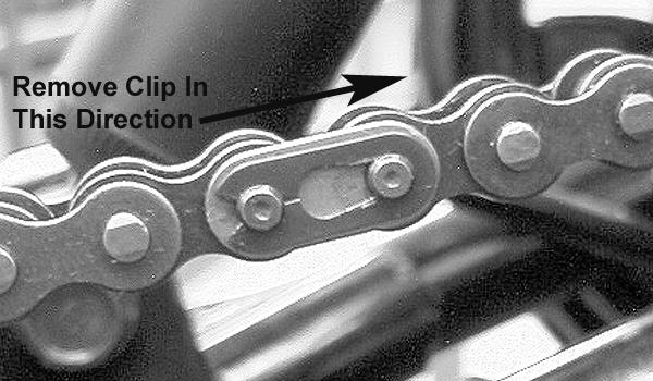
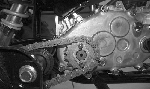
4.Remove the left and right footwells and the left-side footwell mounting plate; then remove the drive sprocket and chain from the transmission output shaft.
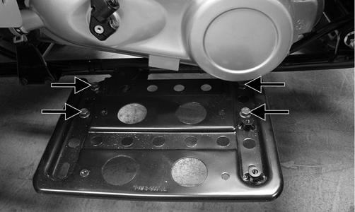
YT002A
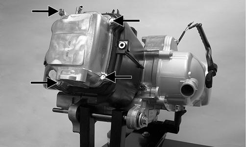
5.Remove the air filter housing cover and air filter element. 6.Remove the intake boot from the carburetor; then remove the cap screws securing the air filter housing to the crankcase and remove the air filter housing and intake boot.

YT006A
7.Remove the exhaust pipe/muffler assembly and related mounting hardware; then remove the shift linkage. Account for a grafoil seal on the exhaust pipe.

YT008A

YT005A
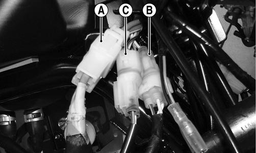
8.Disconnect the electric choke connector (C), stator coil connector (B), and starter harness connector (A); then remove the spark plug cap.
YT010A
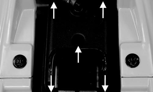
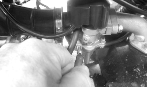
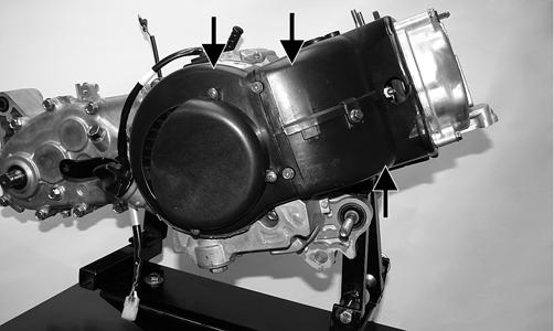
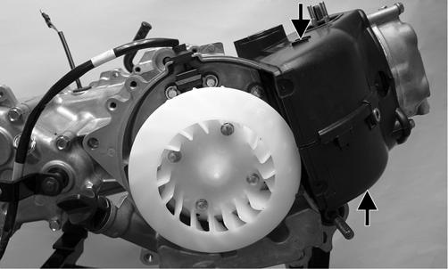
9.Remove the gasline hose from the carburetor. 10.Remove the nuts from the one rear and two front through bolts. Do not remove the bolts at this time. 11.Remove the cooling duct from the front of the V-belt housing; then disconnect the gear shift position switch connectors. 12.Remove the cap screws securing the front engine mounting brackets to the frame; then remove the through bolts and brackets. 13.Slide the engine/transmission forward sufficiently to clear the rear mounting brackets; then swing the rear of the assembly out the left side and remove the engine/transmission from the frame.
YT014
Top-Side Components
NOTE: For efficiency, it is preferable to remove and disassemble only those components which need to be addressed and to service only those components. The technician should use discretion and sound judgment.
NOTE: The engine/transmission does not need to be
removed from the frame for this procedure.
AT THIS POINT
To service any one specific component, only limited disassembly of components may be necessary. Note the AT THIS POINT information in each sub-section.
Removing Top-Side Components
A.CAMSHAFT HOLDER/ROCKER
ARMS B.CYLINDER HEAD/CAMSHAFT NOTE: Arctic Cat recommends the use of new gas-
kets, lock nuts, and seals and lubricating all internal components when servicing the engine/transmission.
1.Remove the intake pipe/carburetor assembly.
Account for an O-ring between the intake pipe and cylinder head. 2.Remove the fan shroud; then remove the cylinder/ cylinder head shroud. Note the location of the carburetor float bowl drain hose clip.
YT016A

YT017A
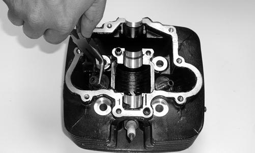
3.Remove the cylinder head cover. Account for the gasket. 4.Rotate the engine to top-dead-center (TDC) on the compression stroke; then remove the cam chain tensioner assembly.
YT095
YT098A
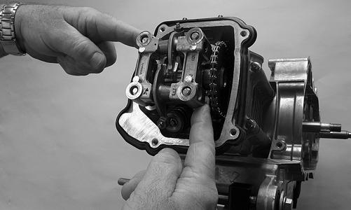
5.Remove the cylinder head nuts on top of the cam shaft holder. Account for four flat washers.
YT106A
6.Remove the camshaft holder noting the location of the two alignment pins. Do not allow the alignment pins to fall into the engine.
YT107
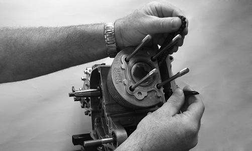
7.Remove the camshaft from the cylinder head and secure the cam chain to prevent it falling into the crankcase.

YT168A
CAUTION
Do not rotate the crankshaft without keeping tension on the cam chain or engine damage could occur.
AT THIS POINT
To service valves and cylinder head, see Servicing TopSide Components sub-section.
8.Remove the cam chain guide.
AT THIS POINT
To inspect cam chain guide, see Servicing Top-Side Components sub-section.
YT112
C.CYLINDER D.PISTON NOTE: Steps 1-8 in the preceding sub-section must
precede this procedure.
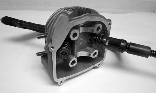
9.Remove the two cap screws from the left side of the cylinder head; then remove the cylinder head.
Account for two alignment pins and remove and discard the cylinder head gasket.

YT109B

YT110A
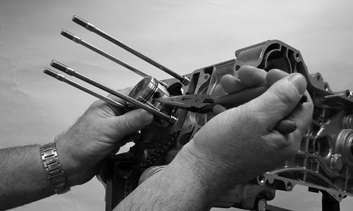
10.Lift the cylinder off the crankcase taking care not to allow the piston to drop against the crankcase.
Account for the gasket and two alignment pins.
11.Remove the cam chain tensioner pivot bolt; then remove the chain tensioner.
AT THIS POINT
To service cylinder, see Servicing Top-Side Components sub-section.
CAUTION
When removing the cylinder, be sure to support the piston to prevent damage to the crankcase and piston.

YT114A
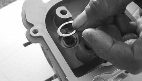
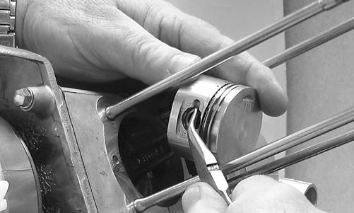
12.Using a needle-nose pliers, remove the circlip securing the piston pin in the piston; then remove the piston pin and piston. Take care not to drop the circlip into the crankcase.
YT115
NOTE: Support the connecting rod with rubber
bands or install a connecting rod holder to avoid damaging the rod.
NOTE: If the existing rings will not be replaced with
new rings, note the location of each ring for proper installation. When replacing with new rings, replace as a complete set only. If the piston rings must be removed, remove them in this sequence.
CAUTION
Do not allow the connecting rod to go down inside the crankcase. If the rod is down inside the crankcase and the crankshaft is rotated, severe damage will result.
AT THIS POINT
To service piston, see Servicing Top-Side Components sub-section.
AT THIS POINT
To service center crankcase components only, proceed to Removing Left-Side Components.
Servicing Top-Side Components
VALVE ASSEMBLY When servicing valve assembly, inspect valve seats, valve stems, valve faces, and valve stem ends for pits, burn marks, or other signs of abnormal wear. NOTE: Whenever a valve is out of tolerance, it must
be replaced.
Cleaning/Inspecting Cylinder Head Assembly Inspect the combustion area of the cylinder head for cracks, burned valves or carbon build-up. NOTE: If valves are discolored, they must be
replaced. Arctic Cat recommends taking heads to a qualified machine shop for valve replacement or valve seat grinding.
REMOVING VALVES NOTE: Keep all valves and valve components as a
set. Note the original location of each valve set for use during installation. Return each valve set to its original location during installation.
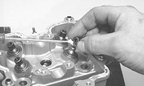
1.Using a valve spring compressor, compress the valve springs and remove the valve cotters. Account for an upper spring retainer.

CC391D
2.Remove the valve seal and the lower remaining spring seat. Discard the valve seal.
CC928
DSC2274
NOTE: The valve seals must be replaced. 3.Remove the valve springs; then invert the cylinder head and remove the valves. Measuring Valve Stem to Guide Clearance 1.Insert a snap gauge 1/2 way down into each valve guide bore; then remove the gauge and measure it with a micrometer.
2.Using a micrometer, measure the valve stem outside diameter. Valve stem to guide clearance must not exceed specifications. 3.If valve stem to guide clearance exceeds specifications, the cylinder head assembly must be replaced. Servicing Valves/Valve Guides/Valve Seats If valves, valve guides, or valve seats require servicing or replacement, Arctic Cat recommends the components be taken to a qualified machine shop for servicing.
Measuring Rocker Arm to Shaft Clearance 1.Using a dial calipers, measure the inside diameter of the rocker arm. 2.Using a micrometer, measure the outside diameter of the rocker arm shaft. 3.Subtract the shaft diameter from the rocker arm diameter. 4.Acceptable clearance must be within specifications. Installing Valves 1.Apply grease to the inside surface of the valve seals; then place a valve guide seal over each valve guide.
CAUTION
If valves are discolored or pitted or if the seating surface is worn, the valve must be replaced. Do not attempt to grind the valves or severe engine damage may occur.
CC144D
2.Insert each valve into its original valve location. 3.Install the valve springs and seats with the closest wound end of the spring directed toward the cylinder head. 4.Place a spring retainer over the valve springs; then using the valve spring compressor, compress the valve springs and install the valve keepers.

YT138
PISTON ASSEMBLY NOTE: Whenever a piston, rings, or pin are out of
tolerance, they must be replaced.
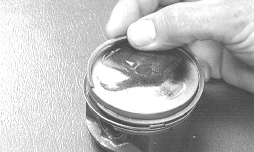
Inspecting Piston 1.Inspect the piston for cracks in the piston pin, boss, top, and skirt areas. 2.Inspect the piston for seizure marks or scuffing. If piston is scored or galled, replace it with a new one. 3.Inspect the perimeter of each piston for signs of
“blowby” indicated by dark discoloration. “Blowby” is caused by worn piston rings, excessive carbon in ring grooves, or an out-of-round cylinder. Removing Piston Rings 1.Starting with the top ring, slide one end of the ring out of the ring-groove.
CC400D
2.Remove and discard each ring by working it toward the top of the piston while rotating it out of the groove. NOTE: New rings must be installed as a complete
set only.
Measuring Piston-Ring End Gap (Installed) 1.Place each piston ring in the wear portion of the cylinder. Use the piston to position each ring squarely in the cylinder.
2.Using a feeler gauge, measure each piston-ring end gap. Acceptable ring end gap must be within specifications.

CC995
Measuring Piston Pin, Connecting Rod Small End, and Piston-Pin Bore 1.Measure the piston pin outside diameter at each end and in the center. If measurement exceeds specifications, the piston pin must be replaced.

ATV-1070
2.Inspect and measure the connecting rod small end inside diameter. If the measurement exceeds specifications, the connecting rod must be replaced (see
Center Crankcase Components in this section). 3.Insert an inside dial indicator into the piston-pin bore. Take two measurements to ensure accuracy.
The diameter must not exceed specifications. If the diameter exceeds specifications, the piston must be replaced.

ATV-1069
Measuring Piston Skirt/Cylinder Clearance 1.Measure the cylinder front to back in six places.
YT137
2.Measure the corresponding piston diameter at a point 15 mm above the piston skirt at a right angle to the piston-pin bore. Subtract this measurement from the measurement in step 1. The difference (clearance) must be within specifications. Installing Piston Rings 1.Install ring expander (4) in the bottom groove of the piston; then install the thin oil rings (3) over the expander making sure the expander ends do not overlap. Stagger the end gaps of the upper and lower thin oil rings according to the illustration. NOTE: Note the direction of the exhaust side of the
piston (5) for correct ring end gap orientation.

ATV-1085B
2.Install the compression rings (1 and 2) so the letter
“T” on the top surface of each ring faces the dome of the piston. Rotate the rings until the ring end gaps are on directly opposite sides of the piston according to the illustration.
NOTE: The chrome (silver) ring should be installed
in the top position.

MD1343C
CAUTION
Incorrect installation of the piston rings will result in engine damage.
CYLINDER/CYLINDER HEAD ASSEMBLY NOTE: If the cylinder/cylinder head assembly can-
not be trued, they must be replaced.
Cleaning/Inspecting Cylinder Head 1.Using a non-metallic carbon removal tool, remove any carbon buildup from the combustion chamber being careful not to nick, scrape, or damage the combustion chamber or the sealing surface. 2.Inspect the spark plug hole for any damaged threads.
Repair damaged threads using a “Time-Sert” insert. 3.Place the cylinder head on the surface plate covered with #400 grit wet-or-dry sandpaper. Using light pressure, move the cylinder head in a figure eight motion. Inspect the sealing surface for any indication of high spots. A high spot can be noted by a bright metallic finish. Correct any high spots before assembly by continuing to move the cylinder head in a figure eight motion until a uniform bright metallic finish is attained.
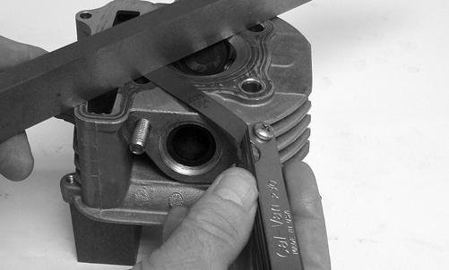
Measuring Cylinder Head Distortion 1.Remove any carbon buildup in the combustion chamber. 2.Lay a straightedge across the cylinder head; then using a feeler gauge, check the distortion between the head and the straightedge. 3.Maximum distortion must not exceed specifications.
CAUTION
Water or parts-cleaning solvent must be used in conjunction with the wet-or-dry sandpaper or damage to the sealing surface may result.

YT123
Cleaning/Inspecting Cylinder 1.Wash the cylinder in parts-cleaning solvent. 2.Inspect the cylinder for pitting, scoring, scuffing, warping, and corrosion. If marks are found, repair the surface using a cylinder hone. 3.Place the cylinder on the surface plate covered with #400 grit wet-or-dry sandpaper. Using light pressure, move the cylinder in a figure eight motion. Inspect the sealing surface for any indication of high spots.
A high spot can be noted by a bright metallic finish.
Correct any high spots before assembly by continuing to move the cylinder in a figure eight motion until a uniform bright metallic finish is attained.
CAUTION
Water or parts-cleaning solvent must be used in conjunction with the wet-or-dry sandpaper or damage to the sealing surface may result.
CC997
Inspecting Cam Chain Guide 1.Inspect cam chain guide for cuts, tears, breaks, or chips. 2.If the chain guide is damaged, it must be replaced. Honing Cylinder 1.Using a slide gauge and a dial indicator or a snap gauge, measure the cylinder bore diameter in three locations from top to bottom and again from top to bottom at 90° from the first measurements for a total of six measurements. The trueness (out-of-roundness) is the difference between the highest and lowest reading. Maximum trueness (out-of-roundness) must not exceed specifications.

CC127D
2.Wash the cylinder in parts-cleaning solvent. 3.Inspect the cylinder for pitting, scoring, scuffing, and corrosion. If marks are found, repair the surface using a #320 grit ball hone. NOTE: To produce the proper 60° cross-hatch pat-
tern, use a low RPM drill (600 RPM) at the rate of 30 strokes per minute. If honing oil is not available, use a lightweight petroleum-based oil. Thoroughly clean cylinder after honing using soap and hot water. Dry with compressed air; then immediately apply oil to the cylinder bore. If the bore is severely damaged or gouged, replace the cylinder.

CC390D
4.At this point, repeat step 1 and if any measurement exceeds the limit, the cylinder must be replaced. Measuring Camshaft Lobe Height 1.Using a micrometer, measure each cam lobe height.

YT129
2.The lobe heights must exceed minimum specifications.
Inspecting Camshaft Bearing/ Sprocket 1.Inspect the camshaft bearings for roughness during rotation or signs of discoloration.
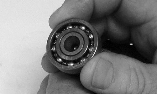
YT128
2.Inspect the timing sprocket for excessive wear.
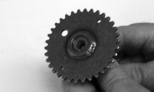
YT127
Installing Top-Side Components
A.PISTON B.CYLINDER 1.Lubricate the piston pin, connecting rod, and piston pin bore with motor oil; then install the piston on the connecting rod making sure there is a circlip on each side and the open end of the circlip is directed upwards or downwards. NOTE: The piston should be installed so the word
“IN” points upward.
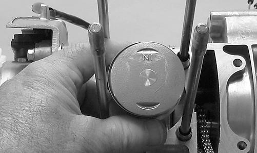
YT161
YT159
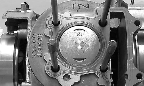
2.Place the two alignment pins into position. Place a new cylinder gasket into position; then place a piston holder (or suitable substitute) beneath the piston skirt and square the piston in respect to the crankcase.

YT161A
3.Lubricate the inside wall of the cylinder; then using a ring compressor or the fingers, compress the rings and slide the cylinder over the piston. Route the cam chain up through the cylinder cam chain housing; then remove the piston holder and seat the cylinder firmly on the crankcase.
CAUTION
The cylinder should slide on easily. Do not force the cylinder or damage to the piston, rings, cylinder, or crankshaft assembly may occur.
YT158
C.CYLINDER HEAD/CAMSHAFT D.CAMSHAFT HOLDER/ROCKER
ARMS NOTE: Steps 1-3 in the preceding sub-section must
precede this procedure.
4.While keeping tension on the cam chain, place the front cam chain guide into the cylinder.
CAUTION
Care should be taken that the bottom of the chain guide is secured in the crankcase boss.
YT112
5.Place a new gasket into position on the cylinder.
Place the alignment pins into position; then place the head assembly into position on the cylinder making sure the cam chain is routed through the chain cavity.
CAUTION
Keep tension on the cam chain to avoid damaging the crankcase boss.

YT168
6.Install two alignment pins into the top of the cylinder head as illustrated.
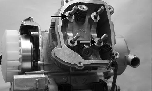
YT169A
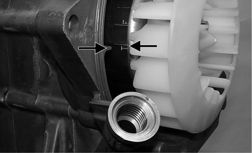
7.Make sure the crankshaft is positioned at TDC; then install the camshaft with the single large reference hole (A) directed up and the two small timing holes (B) parallel to the top of the cylinder head.
YT095A

YT173A
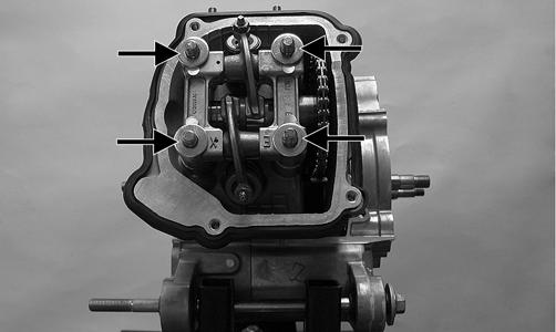
8.Place the camshaft holder into position on the cylinder head making sure the camshaft bearings are seated correctly; then install four flat washers (A) and four nuts (B). Tighten in a crisscross pattern to 15 ft-lb.

YT172A
9.Install the two cap screws securing the left side of the cylinder head and cylinder to the crankcase and tighten to 7 ft-lb.

YT098B
10.Install the cam chain tensioner assembly into the cylinder using a new gasket; then secure with two cap screws and tighten to 7 ft-lb.

YT098C
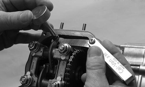
11.Using a small flat screwdriver, release the cam chain tension spring by rotating clockwise; then install the plug bolt and tighten securely. 12.Adjust the valve/tappet clearance (see Periodic
Maintenance/Tune-Up); then install the valve cover with new gasket. Tighten the cap screws to 7 ft-lb.
YT170
YT090A
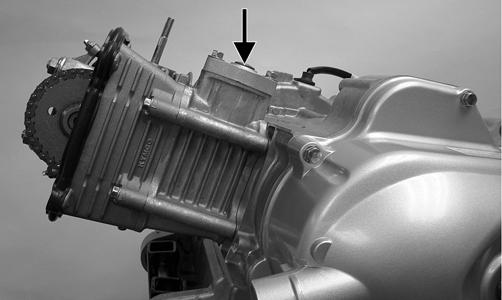
13.Install the intake pipe/carburetor assembly onto the cylinder head using a new O-ring. Tighten the flange nuts to 7 ft-lb.
Left-Side Components
NOTE: For efficiency, it is preferable to remove and disassemble only those components which need to be addressed and to service only those components. The technician should use discretion and sound judgment.
NOTE: The engine/transmission does not have to be
removed from the frame for this procedure.
AT THIS POINT
To service any one specific component, only limited disassembly of components may be necessary. Note the AT THIS POINT information in each sub-section.
Removing Left-Side Components
A.V-BELT COVER B.V-BELT/DRIVE CLUTCH/DRIVEN
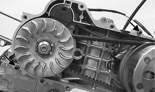
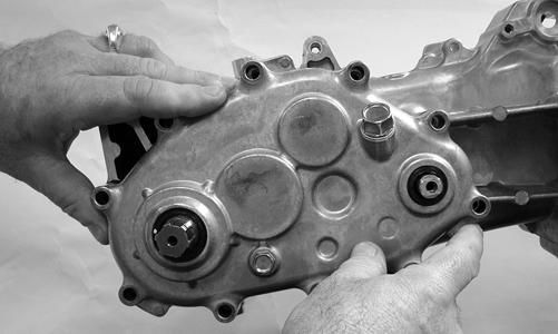
PULLEY C.CENTRIFUGAL CLUTCH D.GEAR POSITION SWITCH E.STARTER ONE-WAY CLUTCH 1.Remove the V-belt cover noting the location of the different-lengthed cap screw and the location of the alignment pins. Account for a gasket.

YT099A
YT160A
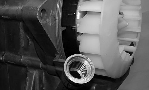
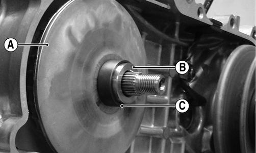
2.Remove the flange nut (A) securing the fixed drive face to the crankshaft. Account for the kick-start ratchet (B).

YT160B
3.Remove the V-belt; then remove the movable drive face (A). Account for a bushing (B) and speed limiter spacer (C).
YT021A
YT022
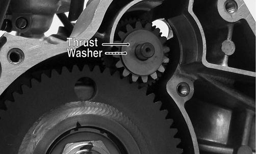
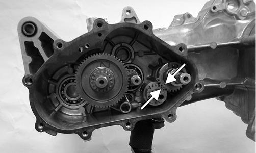
5.Remove the starter reduction gear shield; then remove the starter countershaft housing. Account for a thrust washer (A) and countershaft (B).
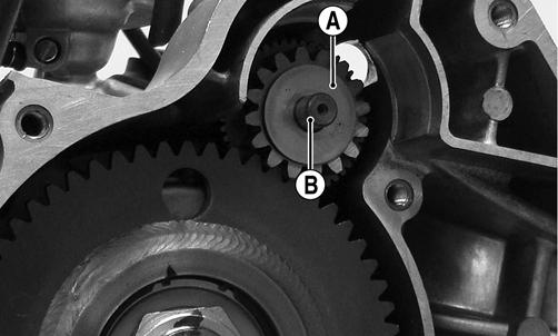
YT024A
NOTE: The thrust washer and countershaft may
come out with the countershaft housing.
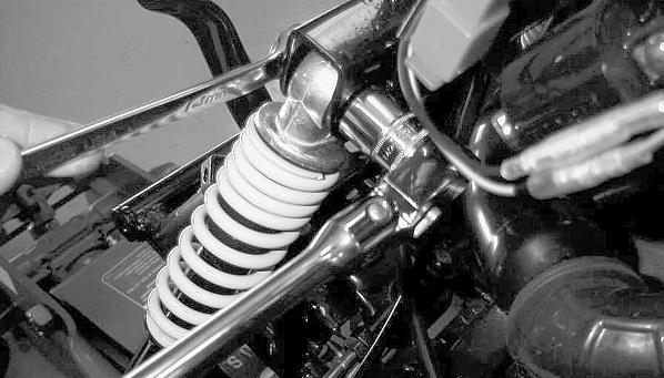
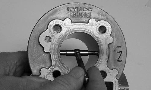
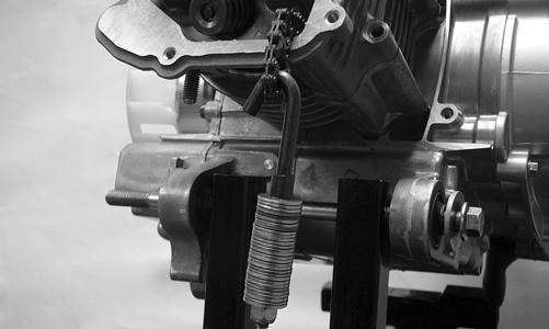
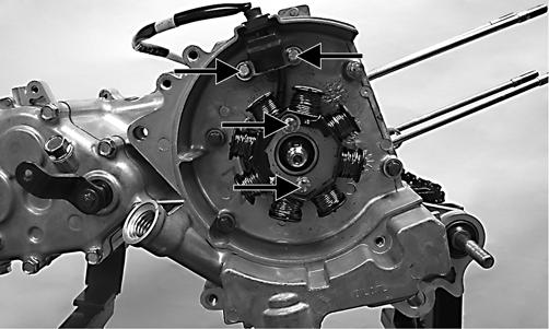
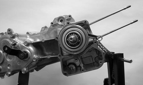
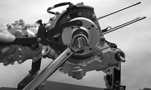
6.Remove the starter one-way nut using Starter One-
Way Clutch Nut Wrench (p/n 0444-191); then install
Starter One-Way Clutch Puller (p/n 0444-188) to the one-way housing.
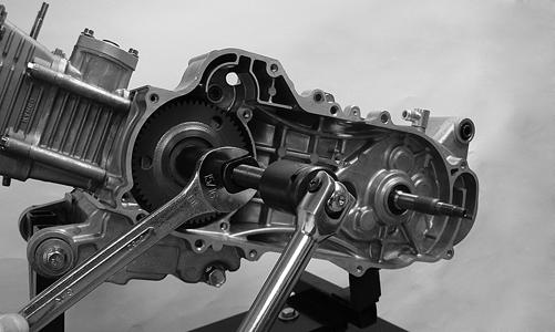
YT104
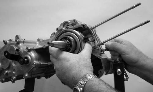
7.Install the push-bolt into the puller; then using two wrenches as illustrated, tighten the push-bolt until the one-way clutch is free of the crankshaft.
YT104
NOTE: It may be necessary to strike the head of the
bolt sharply with a hammer after tightening to free the one-way housing from the crankshaft.
8.Make sure the transmission is in neutral; then remove the gear position switch noting the orientation of the drive pin. Account for an O-ring.

YT028
Installing Left-Side Components
A.GEAR POSITION SWITCH B.STARTER ONE-WAY CLUTCH C.ROTOR/FLYWHEEL D.CENTRIFUGAL CLUTCH E.V-BELT/DRIVE CLUTCH/DRIVEN
PULLEY 1.With the transmission in neutral, install a new O-ring on the gear position switch; then orient the pin as shown and install the switch into the gear case.
Secure with a cap screw and tighten securely.
YT028
2.Secure the gear position switch wire as shown; then tighten the cap screw on the hold-down clip securely.

YT165A
3.Install the starter one-way clutch/gear assembly on the crankshaft; then with a thrust washer on each side of the starter countershaft gear, install the starter countershaft gear/countershaft into the crankcase.
YT024B
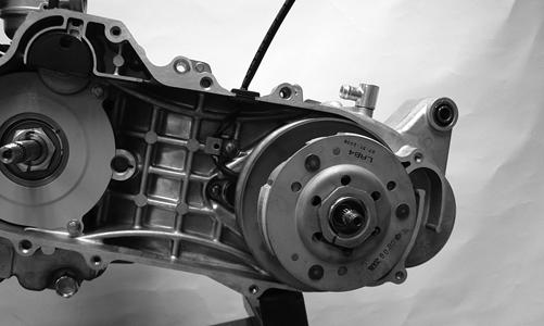
4.Install the starter countershaft housing; then install the starter one-way clutch cover. Tighten the cap screws securely.

YT023A
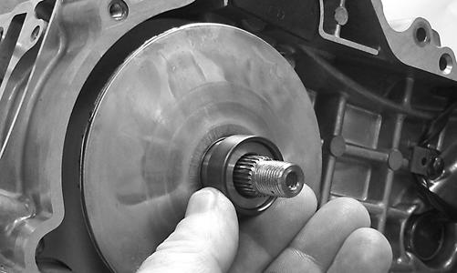
5.Install the driven pulley/centrifugal clutch assembly onto the transmission input shaft; then install the centrifugal clutch housing and secure with a flange nut (coated with red Loctite #271). Tighten to 40 ftlb.

YT147
6.Install the movable drive face, bushing, and speed limiter spacer.
YT164
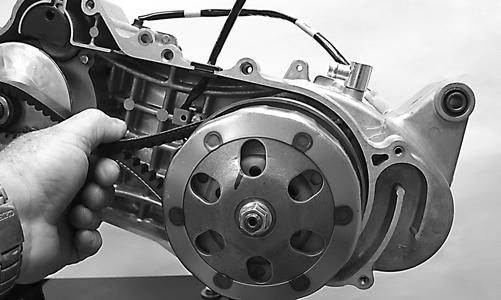
7.Place the V-belt over the driven pulley; then over the bushing/spacer. Pinch the belt in the middle to draw it down into the driven pulley approximately 1 inch.
YT157

YT163A
8.Install the fixed drive face onto the crankshaft and make sure sufficient splines are protruding to allow the kickstart ratchet to slide onto the splines; then install the ratchet (B) and secure with the flange nut (A) coated with red Loctite #271. Tighten to 27.5 ft-lb.
YT160B
CAUTION
Failure to fully engage the splines with the kick-start ratchet could cause false torque reading and crankshaft damage.
9.Install two alignment pins and the gasket; then secure the V-belt cover to the crankcase and tighten the cap screws in a crisscross pattern to 7 ft-lb. Make sure the different-lengthed cap screw is located as illustrated.
YT099A
Right-Side Components
AT THIS POINT
To service center crankcase components only, proceed to Removing Right-Side Components.
NOTE: For efficiency, it is preferable to remove and
disassemble only those components which need to be addressed and to service only those components. The technician should use discretion and sound judgment.
NOTE: The engine/transmission does not have to be
removed from the frame for this procedure.
AT THIS POINT
To service any one specific component, only limited disassembly of components may be necessary. Note the AT THIS POINT information in each sub-section.
Removing Right-Side Components
A.COOLING FAN B.ROTOR/FLYWHEEL C.STATOR COIL D.OIL PUMP 1.Remove the intake pipe/carburetor. Account for an
O-ring in the intake pipe. 2.Remove the cooling fan shroud; then remove the cooling shroud from the cylinder and cylinder head.

YT092
3.Remove the cooling fan; then remove the nut securing the rotor/flywheel.

YT029
4.Remove the rotor/flywheel using the rotor/flywheel puller. Account for a key.

YT145A
5.Remove the stator coil/trigger coil assembly.
YT155A
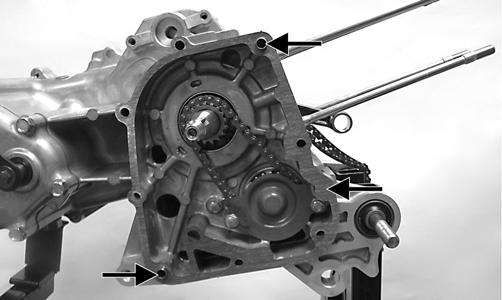
6.Remove the five internal and three external cap screws securing the inner magneto housing to the crankcase; then remove the housing. Account for two alignment pins and a gasket. NOTE: Some engine oil will spill when the cap
screws are loosened.

YT032A
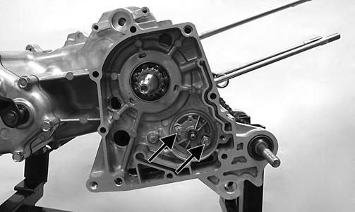
7.Remove the oil pump baffle; then remove the nut from the oil pump shaft and remove the driven gear and drive chain.

YT032
8.Remove the oil pump assembly being careful not to drop the oil pump driveshaft.

YT033
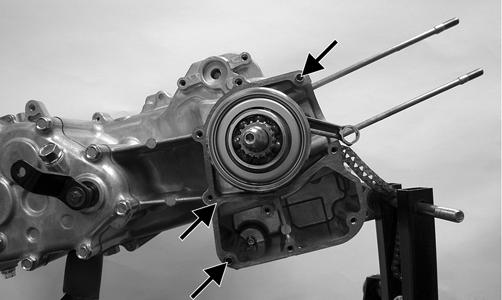
E.TRANSMISSION Removing 1.Note the orientation of the shift arm for assembly; then remove the shift arm from the shift shaft.

YT035
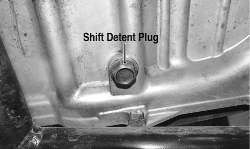
2.Loosen the shift detent plug (A) approximately eight turns; then remove the cap screws securing the transmission case cover. Note the location of two longer cap screws (B).

YT036A
YT220A
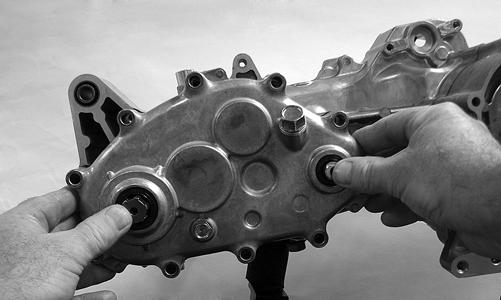
3.Carefully remove the transmission case cover while pressing in on the output driveshaft and shift shaft to leave components in the transmission case. Account for two alignment pins and gasket.

YT041A
NOTE: The driveshaft thrust washer may be stuck
to the cover. Make sure to install it on the driveshaft and keep together for assembly.
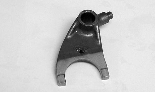
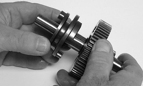
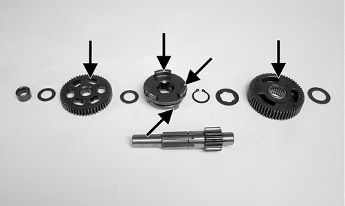
Disassembling NOTE: For steps 4-8 refer to illustration YT041B. 4.Remove the output driveshaft (A); then remove the shift fork shaft (G).

YT041B
5.Remove the main shaft (B) and shift fork together.
Account for the shift fork, a spacer, and a thrust washer.
YT051
YT042A
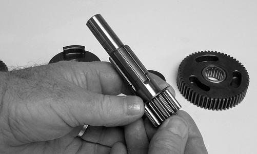
6.Remove the countershaft (C). Account for one thrust washer.

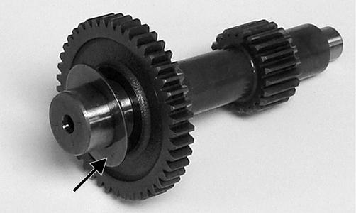
YT043A
7.Remove the shift shaft (E); then remove the shift cam/detent assembly (F). 8.Using a plastic mallet, drive the input driveshaft (D) and bearing from the transmission case.

YT037
F.MAIN SHAFT NOTE: If not absolutely necessary to replace com-
ponents, do not disassemble the main shaft.
To disassemble the main shaft components, use the following procedure. 1.Remove the forward gear spacer and thrust washer; then remove the forward gear. Account for the forward gear bushing and washer.
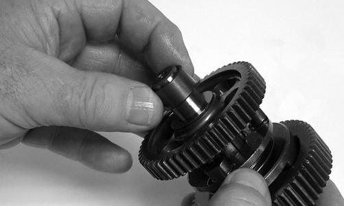
YT063
YT085
2.Remove the forward/reverse shift dog.
YT081
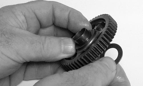
3.Remove the reverse gear snap ring and splined washer; then remove the reverse gear and thrust washer.

YT080
YT053
AT THIS POINT
The main shaft is now completely disassembled for inspection.
Servicing Right-Side Components
TRANSMISSION COMPONENTS 1.Inspect all gears for chipping, excessive wear, flaking, or discoloration.
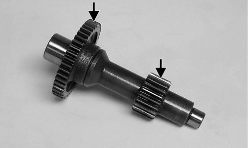

YT048A

YT100A
2.Inspect the shift dog and mating gears for chipping, flaking, discoloration, or signs of excessive wear.
YT100B
3.Inspect all splined shafts for excessive spline wear, twisting, or discoloration. 4.Inspect the shift fork and shift dog mating surfaces for galling, discoloration, or excessive wear. 5.Inspect the shift shaft and shift cam/detent assembly for wear, chipping, or broken spring. 6.Rotate all bearings to check for roughness, discoloration, or looseness in the transmission case or cover.
YT065
7.Inspect the detent spring and ball. Replace any worn or broken component. 8.Examine the transmission case and cover for cracks, discoloration, or chipped bearing bosses.
YT064B
OIL PUMP 1.Inspect the pump for damage. 2.If the oil pump is damaged, it must be replaced. NOTE: The oil pump is a non-serviceable compo-
nent and must be replaced as a complete assembly.
Installing Right-Side Components
NOTE: For steps 1-3, refer to illustration YT100C.
YT100C

A.MAIN SHAFT 1.Install the non-splined reverse thrust washer (A) on the main shaft; then install the reverse gear (B) and splined thrust washer (C). Secure with the snap ring (D) pressing firmly toward the reverse gear to seat in the groove.
YT080
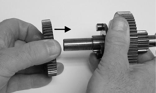
2.Install the forward/reverse shift dog (E), forward gear thrust washer (F), and forward gear bushing (G); then install the forward gear with the flat side toward the shift dog.
YT084A
3.Install the forward gear thrust washer (H) and the spacer (I).
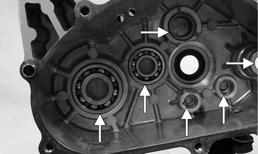
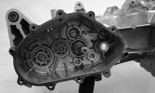
B.TRANSMISSION Assembling 1.Install new oil seals in the transmission case and cover; then coat the inner surfaces of the seals with multi-purpose grease. 2.Making sure the bearing is properly aligned in the transmission case, drive the input driveshaft and bearing into place with a plastic mallet.
The main shaft is now ready for installation into the transmission.
YT047
3.Install the countershaft with thrust washer into the transmission case.
YT043A
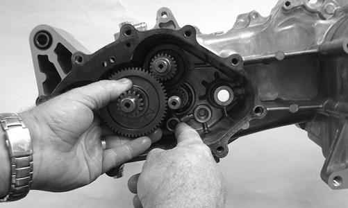
4.Place the shift fork into position on the shift dog; then install the main shaft assembly into the transmission case with the shift fork oriented as shown.
Make sure the spacer and thrust washer do not fall off the shaft.

YT083
5.Install the shift cam/detent assembly; then install the shift shaft aligning the timing index marks.
YT069A
6.Engage the shift fork into the shift cam/detent assembly; then secure with the shift fork shaft.

YT075
7.Install the output driveshaft; then install the thrust washer on the input driveshaft.

YT041A
9.Making sure the input driveshaft thrust washer is installed, carefully install the transmission case cover.

YT039A
YT078
CAUTION
Care must be taken to protect the lips of the shift shaft seal when installing the cover or seal damage may occur.
10.Secure the cover with the cap screws and tighten using the pattern shown to 22 ft-lb; then install the shift detent ball, spring, and plug and tighten securely.

YT036B
YT220A
11.Install the shift arm on the shift shaft and secure with the cap screw. Tighten securely.
YT035
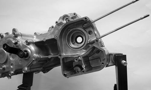
Center Crankcase Components
NOTE: This procedure cannot be done with the
engine/transmission in the frame. Complete Removing procedures for Top-Side, Left-Side, and RightSide must precede this procedure.
NOTE: For efficiency, it is preferable to remove and
disassemble only those components which need to be addressed and to service only those components. The technician should use discretion and sound judgment.
Disassembling Crankcase Halves
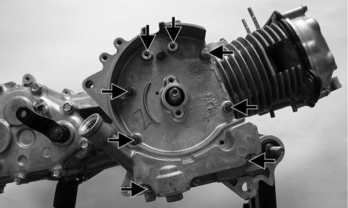
1.Remove one remaining cap screw from the right-side crankcase half; then tap the right-side crankcase half from the left side leaving the crankshaft in the left side. Account for a gasket and two alignment pins.

YT118A
YT119
2.Carefully remove the crankshaft from the left-side crankcase half while holding the timing chain clear of the timing sprocket; then remove the timing chain.
YT121
YT122
AT THIS POINT
The center components are now disassembled for inspection.
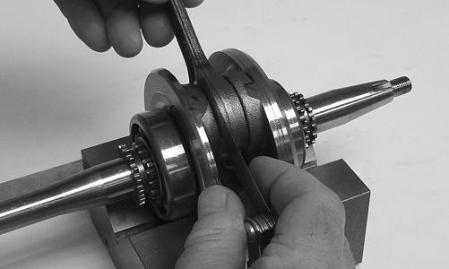
Servicing Crankcase Components
1.Inspect the crankshaft, crankshaft bearings, and connecting rod for excessive wear, damage, or discoloration. 2.Using a thickness gauge, check for the side-to-side clearance between the connecting rod and crankshaft. Clearance must not be greater than 0.05 mm.
YT134
3.Place the crankshaft assembly on a set of V blocks; then using a dial indicator, measure crankshaft runout. Runout must not exceed 0.10 mm.

YT133
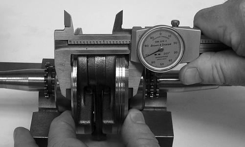
4.Using an appropriate caliper, measure crankshaft web-to-web distance. Measurement must not exceed 45.15 - 45.20 mm.
YT136
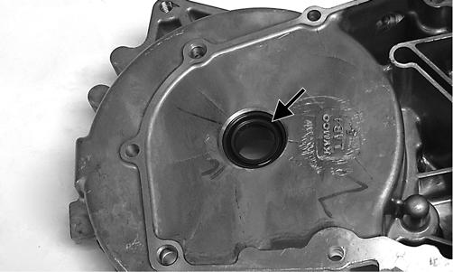
5.Examine crankcase halves for discoloration in bearing bosses, cracks, or signs of warping.

YT122A
6.Replace all oil seals with new seals and coat wear surfaces with clean, fresh grease.
YT153A

Assembling Crankcase Half
1.Place the timing chain into the crankcase; then install the crankshaft assembly into the crankcase half.

YT120
2.Install two alignment pins and a gasket; then install the right-side crankcase half. Secure with a cap screw (threads coated with red Loctite #271) and tighten to 8 ft-lb.
YT119A
YT118A
3.Install the oil pump into the crankcase with the arrow and dot directed upward; then secure with two cap screws and tighten to 7 ft-lb.
YT151A
4.Install the oil pump drive chain and driven gear and secure the gear to the pump shaft with the nut tightened to 7 ft-lb; then install the oil pump baffle and secure with the cap screws. Tighten securely.

YT152A
5.Install the inner magneto housing using a new gasket making sure the alignment pins are correctly located; then secure with the five internal and three external cap screws.
YT152B
YT155A
7.Install the rotor flywheel making sure the crankshaft and flywheel bore are clean and free of any oil; then with the key in place, secure with the flywheel nut coated with red Loctite #271. Tighten to 30 ft-lb.
YT143
8.Install the cooling fan and secure with four cap screws; then install the fan shroud.
Installing Engine/ Transmission
1.From the left side, place the engine/transmission into the frame tilting the top-side forward to clear the frame member.
YT014
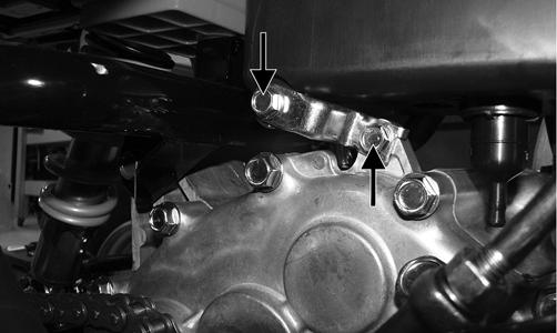
2.Install the two front engine mounting brackets on the frame and tighten the cap screws securely; then install the two front through-bolts. Do not tighten at this time.

YT012
3.Install the rear engine mounting through-bolt and nut; then tighten the front and rear nuts to 32.5 ft-lb. 4.Install the drive sprocket and chain and secure with the spline-lock; then install the cap screws and tighten to 8 ft-lb.
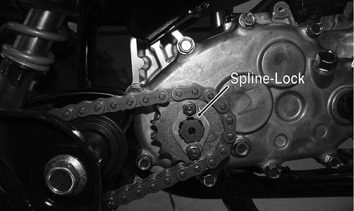
YT009A
5.Install the V-belt housing cooling duct and secure with the clamp; then install the exhaust pipe/muffler assembly using a new grafoil seal in the cylinder head. Tighten the exhaust pipe to cylinder head nuts to 7 ft-lb and the muffler mounting cap screws to 32 ft-lb.
YT008A
YT005A
6.Connect the shift linkage; then install the air filter housing and air filter. Tighten all hardware securely.
YT007A

YT003A
7.Connect the starter harness connector (A), stator coil connector (B), and electric choke connector (C); then install the spark plug cap.
YT010A
8.Connect the gasline hose (A) to the carburetor; then connect the crankcase breather hose (B) to the air filter housing.

YT004A
9.Connect the gear shift position switch connectors to the main harness and secure to the frame with a nylon tie. 10.Install the left-side footwell mounting plate to the frame; then install the left and right footwells and secure to the mountings and fenders. Tighten all hardware securely. 11.Pour the recommended quantity of engine oil into the crankcase; then install the level stick and fill the transmission with the recommended amount of gear lubricant. Install the level plug and fill plug.

YT221A
12.Start the engine and check for any fluid leaks. After a short “test-ride,” shut off the engine and check the fluid levels. Add fluids as required.
Troubleshooting
Problem: Engine will not start or is hard to start (Compression too low) Condition Remedy
1. Piston rings worn excessively 1.Replace rings 2. Cylinder bore worn 2.Replace - rebore cylinder 3. Spark plug seating poorly 3.Tighten plug 4. Starter motor cranks too slowly - does not turn 4.See Electrical System section 5. Valves burned - tappets adjusted too tight 5.Replace valves - adjust tappets
Problem: Engine will not start or is hard to start (No spark) Condition Remedy
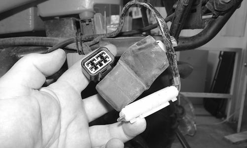
1. Spark plug fouled 1.Clean - replace plug 2. Spark plug wet 2.Clean - dry plug 3. Magneto defective 3.Replace magneto 4. CDI unit defective 4.Replace CDI unit 5. Ignition coil defective 5.Replace ignition coil 6. High-tension lead open - shorted 6.Replace high tension lead
Problem: Engine will not start or is hard to start (No fuel reaching the carburetor) Condition Remedy
1. Gas tank vent hose obstructed 1.Clean vent hose 2. Carburetor inlet needle defective 2.Replace needle 3. Fuel hose obstructed 3.Clean - replace hose 4. Fuel screens obstructed 4.Clean - replace inlet screen - valve screen
Problem: Engine stalls easily Condition Remedy
1. Spark plug fouled 1.Clean plug 2. Magneto defective 2.Replace magneto 3. CDI unit defective 3.Replace CDI unit 4. Carburetor jets obstructed 4.Clean jets
Problem: Engine noisy (Noise seems to come from piston) Condition Remedy
1. Piston - cylinder worn 1.Replace - service piston - cylinder 2. Combustion chamber carbon buildup 2.Clean chamber 3. Piston pin - piston pin bore worn 3.Replace - service pin - bore 4. Piston rings - ring groove(s) worn 4.Replace rings - piston
Problem: Engine noisy (Noise seems to come from clutch) Condition Remedy
1. Clutch shoe(s) worn 1.Replace clutch shoe(s) 2. Driven clutch hub warped - worn 2.Replace clutch
Problem: Engine noisy (Noise seems to come from crankshaft) Condition Remedy
1. Bearing worn - burned 1.Replace bearing 2. Lower rod-end bearing worn - burned 2.Replace bearing 3. Connecting rod side clearance too large 3.Replace thrust washer(s) 4. Engine oil low - incorrect grade 4.Fill crankcase with recommended engine oil
Problem: Engine idles poorly Condition Remedy
1. Magneto defective 1.Replace magneto 2. CDI unit defective 2.Replace CDI unit 3. Spark plug fouled - gap too wide 3.Adjust gap - replace plug 4. Ignition coil defective 4.Replace ignition coil 5. Float level out of adjustment 5.Adjust float height 6. Carburetor jets obstructed 6.Clean jets 7. Pilot screw setting improper 7.Adjust pilot screw
Problem: Engine runs poorly at high speed Condition Remedy
1. Spark plug gap too narrow 1.Adjust gap 2. Ignition coil defective 2.Replace ignition oil 3. Float level too low 3.Adjust float arm height 4. Air cleaner element obstructed 4.Clean element 5. Fuel hose obstructed 5.Clean - prime hose 6. Carburetor jets obstructed 6.Clean jets 7. Air filter inlet pipe obstructed 7.Remove obstruction
Problem: Exhaust smoke dirty or heavy Condition Remedy
1. Piston rings - cylinder worn 1.Replace - service rings - cylinder 2. Cylinder wall scored - scuffed 2.Replace - service cylinder 3. Crankcase over-full of oil 3.Drain excess oil from crankcase - recheck oil level 4. Air filter too much air filter element oil 4.Use recommended type and quantity air filter element oil 5. Carburetor jets incorrect size (too big) 5.Use recommended carburetor jets
Problem: Engine lacks power Condition Remedy
1. Piston ring(s) - cylinder worn 1.Replace - service rings - cylinder 2. Spark plug fouled 2.Clean - replace plug 3. Spark plug gap incorrect 3.Adjust gap - replace plug 4. Carburetor jets obstructed 4.Clean jets 5. Float level out of adjustment 5.Adjust float arm height 6. Air filter element obstructed 6.Clean element 7. Intake manifold leaking air 7.Tighten - replace manifold 8. Brake(s) dragging 8.Adjust brake(s) 9. Drive axle bent - worn bearings 9.Straighten - replace axle 10. Drive chain - sprockets stretched - worn 10.Replace sprocket - chain
Problem: Engine overheats Condition Remedy
1. Carbon deposit (piston crown) excessive 1.Clean piston 2. Engine oil low 2.Add engine oil 3. Octane low - gasoline poor 3.Drain - replace gasoline 4. Oil pump defective 4.Replace pump 5. Oil filter/screen obstructed 5.Clean filter/screen 6. Float level low 6.Adjust float arm height 7. Intake manifold leaking air 7.Tighten - replace manifold 8. Air filter element obstructed 8.Clean element