INSTALLING
Suspension
1. Place the shock absorber spring over the shock absorber, compress the spring, and install the retainer.
The following suspension system components should be inspected periodically to ensure proper operation.
2. Place bushings and sleeves (where appropriate) into shock eyelet; then install shocks with two cap screws and nuts.
A. Shock absorber rods bent, pitted, or damaged. B. Reservoirs damp or leaking. C. Shock absorber body damaged, punctured, or leaking. D. Shock absorber eyelets broken, bent, or cracked. E. Shock absorber eyelet bushings worn, deteriorated, cracked, or missing. F. Shock absorber spring broken or sagging. G. Sway bar mountings tight and bushings secure. H. Proper pre-load and damping for conditions.
SPECIAL TOOLS A number of special tools must be available to the technician when performing service procedures in this section. Refer to the current Special Tools Catalog for the appropriate tool description. Description
3. Tighten the front shock absorber cap screws to 40 ft-lb (head side). Tighten the upper rear shock absorber cap screws to 40 ft-lb and the lower rear shock absorber cap screws to 35 ft-lb. 4. Remove the vehicle from the support stand.
CHECKING/ADJUSTING RIDE HEIGHT NOTE: Ensure the vehicle is on level ground, the tires are properly inflated to 14 psi, and there is an average operating load in the vehicle.
1. Measure from the ground to the bottom of the skid plate along the front sway bar. Measurement should be 10.5 inches.
p/n
Shaft Bullet Tool
0644-404
Inflation Needle
0644-604
Piston Location (IFP) Tool
0644-575
Gas Shock Rod/Body Clamping Tool
0644-425
NOTE: Special tools are available from the Arctic Cat Service Department.
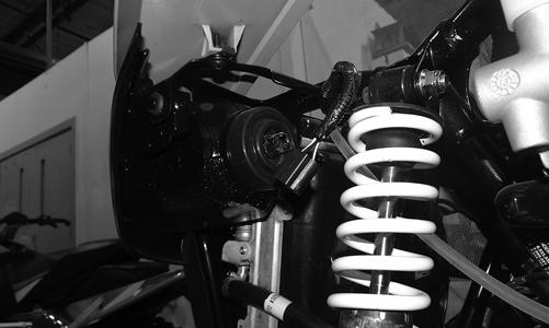
Shock Absorbers
WT492A
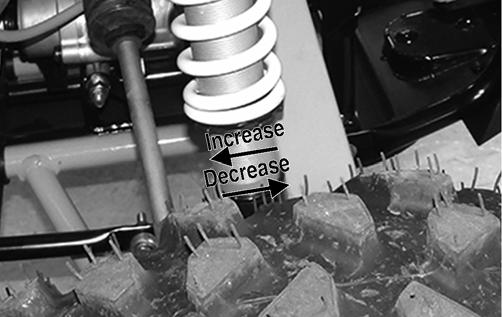
2. If measurement is not as specified, use an appropriate spanner wrench to adjust the left and right spring as required.
REMOVING 1. Secure the vehicle on a support stand to elevate the wheels and to release load on the suspension. 2. Remove the two cap screws and nuts securing each front shock absorber to the frame and lower A-arm. Account for bushings and sleeves from each. 3. Remove the two cap screws and nuts securing each rear shock absorber to the frame and lower trailing arm. Account for bushings and sleeves from each.
CLEANING AND INSPECTING 1. Completely remove pre-load by turning the adjusters to the end of the threads and removing the retainer; then remove the spring. 2. Clean all shock absorber components in parts-cleaning solvent.
WT077B
3. Measure from the ground to the bottom of the skid plate along the receiver hitch. Measurement should be 10 inches.
3. Inspect each shock rod for nicks, pits, rust, bends, and oily residue. 4. Inspect all springs, spring retainers, shock rods, sleeves, bushings, shock bodies, and eyelets for cracks, leaks, and bends. 153