24 minute read
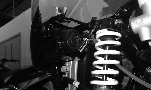
Suspension

The following suspension system components should be inspected periodically to ensure proper operation.
A.Shock absorber rods bent, pitted, or damaged.
B.Reservoirs damp or leaking.
C.Shock absorber body damaged, punctured, or leaking.
D.Shock absorber eyelets broken, bent, or cracked.
E.Shock absorber eyelet bushings worn, deteriorated, cracked, or missing.
F.Shock absorber spring broken or sagging.
G.Sway bar mountings tight and bushings secure.
H.Proper pre-load and damping for conditions. SPECIAL TOOLS A number of special tools must be available to the technician when performing service procedures in this section. Refer to the current Special Tools Catalog for the appropriate tool description.
Shaft Bullet Tool Inflation Needle
Description p/n
0644-404 0644-604
Piston Location (IFP) Tool Gas Shock Rod/Body Clamping Tool 0644-575 0644-425
NOTE: Special tools are available from the Arctic
Cat Service Department.
Shock Absorbers
REMOVING 1.Secure the vehicle on a support stand to elevate the wheels and to release load on the suspension. 2.Remove the two cap screws and nuts securing each front shock absorber to the frame and lower A-arm.
Account for bushings and sleeves from each. 3.Remove the two cap screws and nuts securing each rear shock absorber to the frame and lower trailing arm. Account for bushings and sleeves from each. CLEANING AND INSPECTING 1.Completely remove pre-load by turning the adjusters to the end of the threads and removing the retainer; then remove the spring. 2.Clean all shock absorber components in parts-cleaning solvent. 3.Inspect each shock rod for nicks, pits, rust, bends, and oily residue. 4.Inspect all springs, spring retainers, shock rods, sleeves, bushings, shock bodies, and eyelets for cracks, leaks, and bends. INSTALLING 1.Place the shock absorber spring over the shock absorber, compress the spring, and install the retainer. 2.Place bushings and sleeves (where appropriate) into shock eyelet; then install shocks with two cap screws and nuts. 3.Tighten the front shock absorber cap screws to 40 ft-lb (head side). Tighten the upper rear shock absorber cap screws to 40 ft-lb and the lower rear shock absorber cap screws to 35 ft-lb. 4.Remove the vehicle from the support stand. CHECKING/ADJUSTING RIDE HEIGHT NOTE: Ensure the vehicle is on level ground, the
tires are properly inflated to 14 psi, and there is an average operating load in the vehicle.
1.Measure from the ground to the bottom of the skid plate along the front sway bar. Measurement should be 10.5 inches.
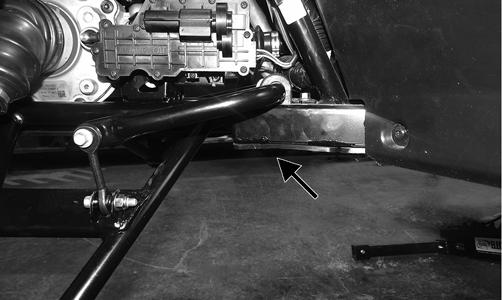
WT492A
2.If measurement is not as specified, use an appropriate spanner wrench to adjust the left and right spring as required.
WT077B
3.Measure from the ground to the bottom of the skid plate along the receiver hitch. Measurement should be 10 inches.
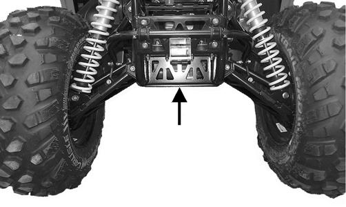
WT590A
4.If measurement is not as specified, use an appropriate spanner wrench to adjust the left and right spring as required.


WT078B
REBUILDING Inspection Inspect all components for any signs of wear or damage and replace parts as necessary. Preliminary Set-Up 1.Clean and dry the shock before beginning disassembly. 2.Stroke the shock to assess its condition and function.
Compress and rebound adjustment positions should be noted. NOTE: This is done by turning the adjustment
knobs clockwise while counting the number of clicks until the adjustment knob is fully closed or bottomed. There are six clicks per full 360° revolution of the adjustment knob. After noting positions, open all adjustment knobs by turning them counter-clockwise fully open.
NOTE: Throughout all procedures as a general rule,
replace all volatile parts (seals, O-rings, bearings, etc.).
DISASSEMBLING
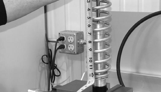
NOTE: Measure spring preload before removing the
spring.
FX068
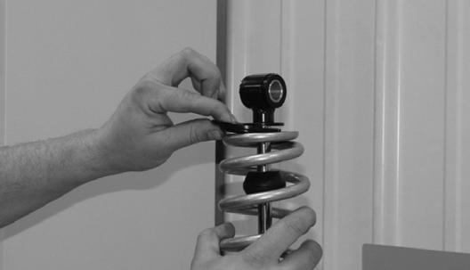
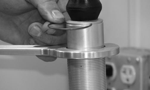
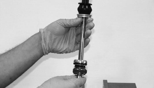
1.Loosen the spring preload adjuster rings with spanner wrenches.
2. Remove the spring retainer and spring.
FX067
FX066
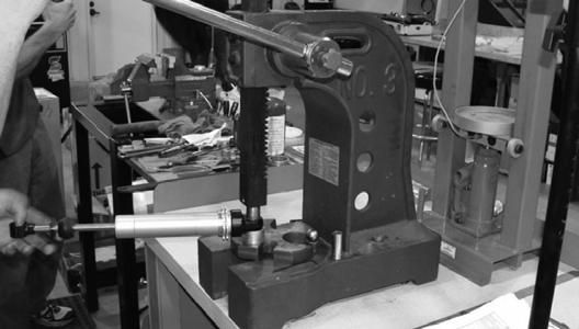
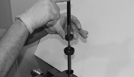
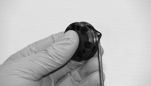
3. Press the rubber-bonded bushing out from the body end cap and eyelet bushings.
FX064
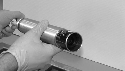
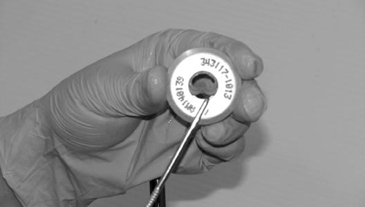
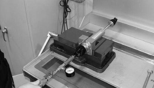
4. Secure the shock eyelet in the vise and insert the nitrogen needle. Fully depress the needle to release nitrogen pressure from the shock. After installing the appropriate body cap removal tool, insert the retaining wire into the groove between the cap and body.

FX061

FX060
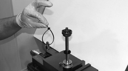
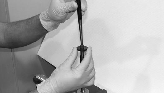
6. Using a valve shim, remove the retaining wire and pull the shaft assembly out of the body.
FX063

FX062
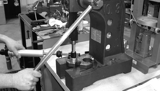
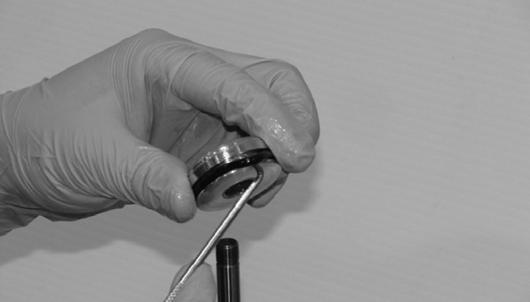
5. Tap upward on body cap removal tool to release cap; then depress the bearing assembly to full expose retaining wire.
FX059

FX058
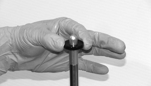
7. Dispose of used oil in an environmentally-acceptable manner; then use a body clamp block to secure the body in the vise.

FX057
FX056
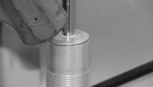
8. Apply sufficient heat to the body cap to break down the thread lock bond between the body cap and body.
Remove any thread lock residue from the body and body cap using a wire brush and small pick.


FX055

FX054
9. Remove the O-ring from the body cap; then push the
IFP out of body.

FX053
FX052
10. Remove the lock nut.

FX049
11. Remove the rebound valve stack and cable tie the valves together.
FX048
FX047
12. Remove the piston assembly; then remove the compression valve stack and cable tie it together. 13. Remove the rubber washer, bearing assembly, bearing cap, bumper, and washer.

FX044

FX043
14. Use Gas Shock Rod/Body Clamping Tool to secure the shaft; then apply sufficient heat to the eyelet to break the thread lock bond between the shaft and eyelet.

FX042

FX041
15.Using a small pick, remove all seals and O-rings from the bearing cap and bearing assembly. If a bearing is required in the bearing assembly, replace the bearing assembly.
FX040
FX039
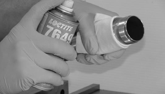
ASSEMBLING 1. Apply Loctite Primer #7649 to the shaft. Allow proper curing time before applying green Loctite #638 to the shaft.

FX038
2. Tighten to 50 ft-lb.

FX037

FX036
3. Assemble the shaft with eyelet washer and bumper. NOTE: Always lubricate seals and O-rings with a
thin layer of molybdenum grease before installing.

FX035

FX034
4. Replace the wiper seal in the bearing cap.

FX033
5. Replace the U-cup seal and O-ring.

FX032

FX031
6. Using Shaft Bullet Tool, install the bearing cap assembly and bearing assembly.

FX030

FX029
7.Install the bumper and compression valve stack.
FX028 FX027
8. Replace the O-ring and bearing on the piston. Install the piston making sure the compression side of piston is next to the compression shims.
FX026

FX025
9. Install the rebound valve stack; then replace the valve stack. Replace the lock nut and tighten to 18 ft-lb. Set aside for later assembly.

FX023
10. Replace the O-ring on the IFP. Apply a thin layer of molybdenum grease to the body before installing the
IFP into the body with the IFP relief contour facing towards the top of the body.


FX019
NOTE: When setting IFP depth, note the shock
absorber IFP shuttles 0.480” during installation.
A.The designed depth of the IFP must be decreased by 0.480” on the this shock absorber when the IFP depth is determined from the top of the body.
B.Example: 8.164”-0.480” = 7.684” installed IFP depth. NOTE: Handle the body carefully once the IFP is
set.
FX022


FX021
11. Apply Loctite Primer #7649 to the body and set the
IFP depth. 12. Replace the O-ring in the body cap. If the shock has been rebuilt several times, the body cap assembly may need to be replaced.

FX018
13. Apply green Loctite #638 two threads wide for 360° two threads up from the start of threads. Ensure the
Loctite does not make contact with the O-ring. Secure the body in Gas Shock Rod/Body Clamping Tool and tighten the body cap to 75 ft-lb.


FX018
14. Verify the IFP depth is correct. Fill the body with specified oil 3/8” from top of body. Pass a propane torch quickly over the body to eliminate any air bubbles in oil.

FX015

FX014
15. Slide the bearing assembly to the bottom of shaft before inserting. Insert the shaft assembly into the oil slowly allowing air bubbles to escape.

FX012
16. Push the bearing assembly just past the retainer groove in the body; then install the wire retainer.

FX011

FX010
17. Once the wire retainer is fully installed, slowly push the shaft assembly down. DO NOT pull the shaft out.
Clean any excess oil off the body. NOTE: If the shaft rebounds upward, it has hit the
IFP meaning the IFP will need to be reset.


FX007

FX008
18. Secure the body with body clamps and ensure the shaft has room to fully extend when charged. Charge with nitrogen using Inflation Needle to the specified pressure for about 10 seconds; the shaft should fully extend.
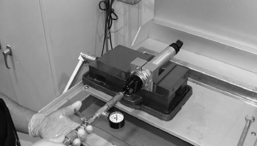
FX007
FX006
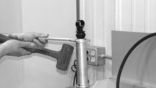
19. Inspect both ends of shocks for leaks. Use rubber mallet to secure bearing cap assembly.
FX005
FX004
20. Install the body cap and eyelet bushings.

FX003
FX002
21. Clean the assembly and install the spring to the desired preload setting.

FX001
Front A-Arms
REMOVING UPPER 1.Lift and support the vehicle with a support stand to allow access to the front suspension. 2.Remove the front wheels. 3.Remove the cotter pin and hub nut securing the hub.

WT328A
4.Remove and discard the “patch-lock” cap screws securing the brake caliper to the hub.

WT287A
5.Remove the cotter pin and nut securing the tie rod end to the knuckle; then remove the tie rod end from the knuckle.

WT330A
6.Remove and discard the cap screws securing the ball joints to the knuckle.

WT329A
CAUTION
Support the knuckle when removing the cap screws or damage to the threads will occur.
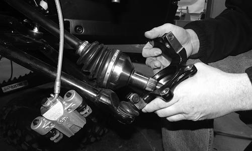
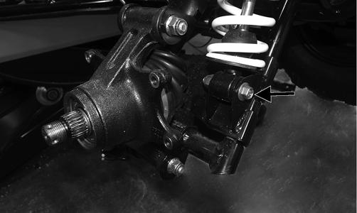
7.Tap the ball joints out of the knuckle; then remove the knuckle. 8.Remove and discard the cap screw securing the lower shock eyelet to the upper A-arm. Remove the shock from the A-arm.
WT498A
9.Remove the brakeline hose routing clip from the upper A-arm; then remove the cap screw securing the
A-arm to the frame. Remove the A-arm. NOTE: Having the steering rack turned completely
to the left and the clamp orientated as shown will aid in removing the cap screw.

WT334
10.Remove the snap ring securing the ball joint in the Aarm. Remove ball joint.

WT496
NOTE: Remove the ball joint only if replacement is
necessary.
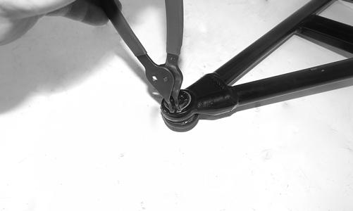
11.Remove and discard the cap screw and lock nut securing the sway bar link to the lower A-arm.
WT494A
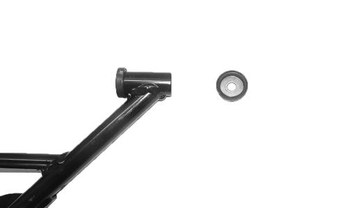
12.Remove the seals and sleeve and inspect for cracks, nicks, or tears. NOTE: Remove the bushings only if they must be
serviced.
13.Place the A-arm in a bench vise and using an appropriate tool, drive out and discard the bushings.

WT600
REMOVING LOWER NOTE: Having the steering rack turned completely
to the left and the clamp orientated as shown will aid in removing the cap screw.

WT333
1.Remove and discard the cap screw and lock nut securing the sway bar link to the lower A-arm.
WT494A
2.Remove the front bumper. NOTE: The front bumper will need to be removed to
remove the lower A-arm cap screw from the frame.
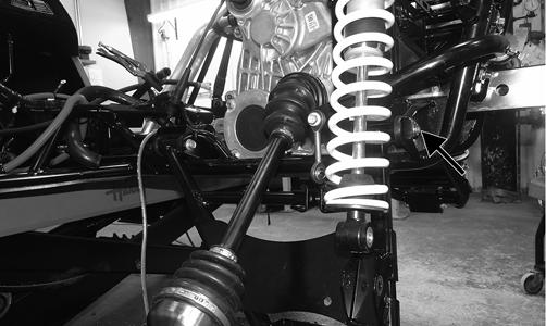
3.Remove the cap screw and discard the lock nut securing the lower A-arm to the frame. Remove the A-arm.
WT492A

WT493A
4.Remove the seals and sleeve and inspect for cracks, nicks, or tears. NOTE: Remove the bushings only if they must be
serviced.
5.Place the A-arm in a bench vise and using an appropriate tool, drive out and discard the bushings.
WT600
CLEANING AND INSPECTING 1.Clean all of the A-arm components in a parts-cleaning solvent. 2.Clean the ball joint opening of all residual Loctite, grease, oil, or dirt. 3.Inspect the A-arms for bends, cracks, and worn bushings. 4.Inspect the ball joint mounting holes for cracks or damage. 5.Inspect the frame mounts for signs of damage, wear, or weldment damage.

WT599
2.Place the A-arm in a bench vise and using a 16 mm reamer, ream out the bushings.

WT596
3.Insert the sleeve into the A-arm and apply molybdenum grease to the inside of the seals. Install the seals on the A-arm. 4.Apply Loctite Primer “T” to the A-arm socket; then apply Green Loctite #609 to the entire outside diameter of the ball joint. Install the ball joint into the A-arm and secure it with the snap ring.

WC237
WT497
5.Install the lower A-arm into the frame mounts and secure it with the cap screw and new lock nut. Fingertighten only at this time. 6.With a new “patch-lock” cap screw and new lock nut, secure the sway bar link to the lower A-arm. Tighten to 20 ft-lb.
WT494A
7.Tighten the lower A-arm cap screw to 40 ft-lb. 8.Install the upper A-arm to the frame with the cap screw and new lock nut. Finger-tighten only at this point.
WT334
9.Route the brakeline hose underneath the upper A-arm and secure it with the clip. Tighten to 30 in.-lb. 10.Install the knuckle on the lower ball joint using a new
“patch-lock” cap screw. Finger-tighten only at this time. With the axle going through the center of the knuckle, rotate it upward and secure the upper A-arm to the knuckle using a new “patch-lock” cap screw.
Tighten the cap screws to 35 ft-lb.
WT332
11.Install the tie rod end and secure it with the castle nut (coated with red Loctite #271). Tighten to 55 ft-lb; then install a new cotter pin and spread the pin to secure the nut.
WT330A
12.Install the hub assembly and secure it with the hub nut. Tighten to 200 ft-lb and install the new cotter pin.
Spread the pin to secure the nut.
WT328A
NOTE: During assembly, new cotter pins should
always be used.
NOTE: If the cotter pin cannot be inserted due to
misalignment of the hole and the slots in the nut, always tighten the nut until it is properly aligned.
13.Using a new “patch-lock” cap screw and existing washer, secure the shock to the upper A-arm. Tighten to 25 ft-lb.
WT498A
14.Tighten the cap screw securing the upper A-arm to the frame to 35 ft-lb. 15.Using new “patch-lock” cap screws, secure the brake caliper to the brake disc. Tighten to 20 ft-lb.
WT287A
16.Install the wheels and tighten the wheel nuts in 20 ftlb increments to a final torque of 40 ft-lb (steel wheel), 60 ft-lb (aluminum wheel w/black nuts), or 80 ft-lb (aluminum wheel w/chrome nuts). 17.Install the front bumper; then remove the vehicle from the support stand.
Rear A Arms
REMOVING 1.Lift and support the vehicle on a support stand that allows access to the rear suspension with the rear tires off of the floor. Remove the wheels. NOTE: The upper A-arm can be removed without
removing the hub or the knuckle. If it is the technician’s objective to only remove the upper A-arm, proceed to step 5.
2.Remove and discard the “patch-lock” cap screws securing the brake caliper to the hub.

WT418A
3.Remove and discard the cotter pin from the hub nut; then remove nut and hub.
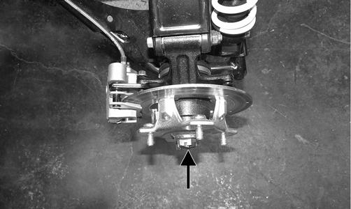
WT418B
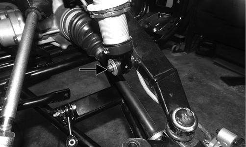
4.Remove the lower shock cap screw and discard the nut.
WT417A
5.Remove the cap screws securing the upper A-arm to the frame and knuckle. Discard the nuts.


W446A
NOTE: The drive axle does not need to be removed
for this procedure.
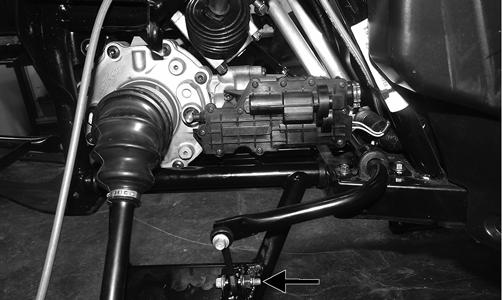
7.Remove and discard the cap screw and lock nut securing the sway bar link to the lower A-arm (A). Remove the cap screw and clip securing the brake line to the lower A-arm (B); then remove the cap screw and nut securing the shock to the lower A-arm (C).

WT448A
8.Remove the cap screws and nuts securing the lower
A-arm to the frame. Discard the nuts.
WT445A
9.Remove the seals and sleeve.

WT444
NOTE: Remove the bushings only if they must be
serviced.
10.Place the A-arm in a bench vise and using an appropriate tool, drive out and discard the bushings.
WT600
CLEANING AND INSPECTING 1.Clean all A-arm components in parts-cleaning solvent. 2.Inspect the A-arm for bends, cracks, and worn bushings. 3.Inspect the frame mounts for signs of damage, wear, or weldment damage. INSTALLING NOTE: If only the upper A-arm was removed, skip to
step 6.
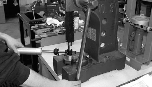
1.Using a suitable press, press in the new bushing.
WT596
3.Insert the sleeve into the A-arm; then apply grease to the seal and insert it into the end of the A-arm along with the end caps.
WT449
4.Install the lower A-arm into the frame mount and secure with cap screws and new lock nuts (A). Only finger tighten at this point. Install the shock into the lower A-arm and secure it with the cap screw and new lock nut (B). Only finger tighten at this point. Install the sway bar link into the lower A-arm and secure it with the new “patch-lock” cap screw and lock nut (C).
Only finger tighten at this point. Install the cap screw and clip securing the brake line to the lower A-arm (D).

WT448B
5.Tighten cap screw (A) to 35 ft-lb, cap screw (B) to 35 ft-lb, cap screw (C) to 20 ft-lb, and cap screw (D) to 20 in.-lb. 6.Using the existing cap screws and new lock nuts, secure the knuckle to the upper and lower A-arms.
Tighten to 35 ft-lb. NOTE: It is important that the hub is installed in a
manner that allows you to read the text.
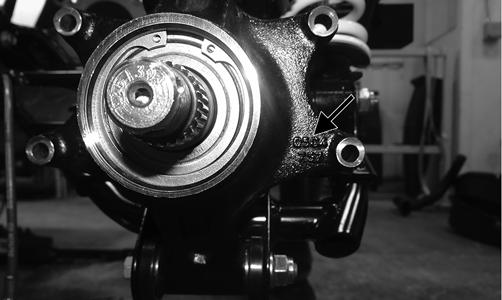
WT450A
7.If the upper A-arm was removed, insert the sleeve into the end of the upper A-arm. Apply grease to the seals and install into the A-arm.
WT449
8.Install the upper A-arm into the frame. Mount and secure the hub with the cap screws and new locking nuts. 9.Install the hub assembly and using an appropriate spanner wrench, secure the hub to the axle with the castle nut. Tighten to 200 ft-lb.
WT451
10.Install a new cotter pin and spread the pin to secure the nut. NOTE: If the pin does not line up with the castle nut,
always tighten the nut to the next opening and install the pin.
11.Using new “patch-lock” cap screws, install the brake caliper and tighten to 20 ft-lb. 12.Install the wheels and tighten the wheel nuts in 20 ftlb increments to a final torque of 40 ft-lb (steel wheel), 60 ft-lb (aluminum wheel w/black nuts), or 80 ft-lb (aluminum wheel w/chrome nuts). 13.Remove the vehicle from the stand.
Front Sway Bar
REMOVING 1.Remove the front wheels (see Wheels and Tires in this section). 2.Remove and discard the cap screws and lock nuts securing the sway bar to the A-arm links.

WT323A
3.Remove the sway bar bushing retainers and bushings and slide the sway bar out of the vehicle. INSPECTING 1.Inspect the sway bar for any signs of twisting or cracking. 2.Inspect the bushing retainers and bushings for any signs of wear or damage. INSTALLING 1.Using new “patch-lock” cap screws and new lock nuts, install the sway bar into position and secure it to the lower A-arm links. 2.Install the bushing retainers and bushings. Fingertighten the cap screws only at this point.

Rear Sway Bar
REMOVING 1.Remove and discard the cap screws and lock nuts securing the sway bar link to the lower A-arms on both sides.

WT320A
2.Remove the cap screws securing the sway bar to the frame and remove the sway bar. Account for the bushing retainers and bushings.

WT315B
INSPECTING 1.Inspect the sway bar for any signs of twisting or cracking. 2.Inspect the bushing retainers and bushings for any signs of wear or damage. INSTALLING 1.Using new “patch-lock” cap screws and new lock nuts, secure the sway bar to the lower A-arm link. Finger-tighten only at this point. 2.Install the bushings and bushing retainers. Fingertighten only at this point. 3.Tighten the lower A-arm links to 20 ft-lb; then tighten the sway bar link to 35 ft-lb.
Wheels and Tires
TIRE SIZE
! WARNING
Use only Arctic Cat approved tires when replacing tires. Failure to do so could result in unstable vehicle operation.
The Wildcat Trail is equipped with low-pressure tubeless tires of the size and type listed in General Information. Do not under any circumstances substitute tires of a different type or size.
TIRE INFLATION PRESSURE Front and rear tire inflation pressure should be as specified in the General Information section. REMOVING 1.Secure the vehicle on a support stand to elevate the wheels.
2.Remove the nuts securing the wheels; then remove the wheels. CLEANING AND INSPECTING 1.Clean the wheels and hubs with parts-cleaning solvent. 2.Clean the tires with soap and water. 3.Inspect each wheel for cracks, dents, or bends. 4.Inspect each tire for cuts, wear, missing lugs, and leaks. INSTALLING Install the wheels and tighten the wheel nuts in 20 ft-lb increments to a final torque of 40 ft-lb (steel wheel), 60 ftlb (aluminum wheel w/black nuts), or 80 ft-lb (aluminum wheel w/chrome nuts). CHECKING/INFLATING 1.Using an air pressure gauge, measure the air pressure in each tire. Adjust the air pressure as necessary to meet the recommended inflation pressure. 2.Inspect the tires for damage, wear, or punctures.
! WARNING
Always use the size and type of tires specified. Always maintain proper tire inflation pressure.
CAUTION
Do not mix tire tread patterns. Use the same pattern type on front and rear. Failure to heed warning could cause poor handling qualities of the vehicle and could cause excessive drive train damage not covered by warranty.
! WARNING
Do not operate the vehicle if tire damage exists.
NOTE: If repair is needed, follow the instructions
found on the tire repair kit or replace the tire.
Troubleshooting
Problem: Suspension too soft Condition Remedy
1. Spring preload incorrect 1.Adjust preload 2. Spring(s) weak 2.Replace spring(s) 3. Shock absorber damaged 3.Replace shock absorber
Problem: Suspension too stiff Condition Remedy
1. Spring preload incorrect 1.Adjust preload 2. A-arm-related bushings worn 2.Replace bushing
Problem: Suspension noisy Condition Remedy
1. Cap screws (suspension system) loose 1.Tighten cap screws 2. A-arm-related bushings worn 2.Replace bushings
Problem: Vehicle pulling or steering erratic Condition Remedy
1. Vehicle steering is erratic on dry, level surface 1.Check front wheel alignment and adjust if necessary (see Steering/Frame/Controls) 2. Vehicle pulls left or right on dry, level surface 2.Check air pressure in tires and adjust to specifications
Printed in U.S.A. Trademarks of Arctic Cat Inc., Thief River Falls, MN 56701 p/n 2260-418