8 minute read
Requirements

from 2014 Eaton Fuller Auto Shift and UltraShift Transmissions TRIG0930 Installation Guide Manual - PDF

Eaton AutoShift/UltraShift Gen 3 transmission systems installed at OEM facilities must meet the requirements and be approved using the Eaton Transmission Application Approval Form. Please contact Eaton Application Engineering or your OEM's Application department for the latest Application form.
1. Cab Floor Access Plate - A cab floor access plate is necessary for access and removal of components from the transmission top. Plate size must be sufficient to allow removal of the transmission Controller or the Electric Shifter. 2. Clutch Requirements - Power assisted clutch release system is required for all rear engine coach applications. All Heavy Duty AutoShifts require adjustment free clutches. All UltraShift DM3 use the DM Clutch module. It is the OEM responsibility to ensure the engine is not allowed to idle between 625 and 825 rpm with HD UltraShift DM3 clutch modules. Base engine idle is recommended at 625 rpm and all methods (cruise/idle/PTO switch) used to raise the idle have a 200 rpm increment. 3. Lubrication Requirements - Transmission Gear Box - Eaton® Roadranger® CD50 or equivalent E500 synthetic as specified in Eaton publication TCMT0021.WetClutch for UltraShift AW3 uses synthetic Dexron III, VI, or Allison TransSynd. Approved lubricants are specified in Eaton publication TCMT0021.[see page 16] 4. Electrical Wiring Requirements - It is the OEM responsibility to provide power and ground to the Transmission Controller (TECU) from a reliable battery source from the battery which supplies the starter. The power (+) connection must include overload protection per Federal Motor Carrier Safety Regulations, Section 393.31.The TECU Main Power and Ground must be a direct connection from the battery posts to the TECU connector. At 120°C, these conductors must be able to carry 30 amps @ 9 volts with no more than 0.05 ohms per wire (0.1 ohms total) for a total voltage drop from the battery posts to the TECU connector not to exceed 3.0 volts. • All wiring installation shall conform to Federal Motor Carrier Safety Administration Regulations Sections 393.27 Wiring specifications; 393.28 Wiring to be protected; 393.29 Grounds; 393.31 Overload protective devices; and 393.33 Wiring, installation.[see page 37] • The cable for the Deutsch connector shall be: - 16 GXL max 18 TXL min for Communication and control wires - 12 GXL for Power Supply wires - 12 GXL or 14 SXL for V-Ignition wires Note: These sizes are requirements for proper connector sealing and current carrying capacity.[see page 37] • When the Eaton Push Button Shift Control is used the CAN (Control Area Network communications link between the Shift Control and the Transmission Controller) must be a J-1939/15 twisted pair cable.[see page 49] • The J-1939 (the communications link between the Transmission ECU and the Engine Controller ECM) must follow SAE J-1939 specifications for either J-1939/11 or J-1939/15. [see page 61] • The diagnostic connector (6-pin required 9-pin recommended) must be easily accessible and mounted on the drivers side of the cab.[see page 60] • Splices are not allowed.[see page 37] • The Main Power 30 amp fuse connection for the Transmission ECU must be identified with a tag at the battery.[see page 56] • Battery Positive and Negative must be disconnected PRIOR to any type of welding on any Eaton Automated transmissionequipped vehicles.[see page 54] • Battery Negative must be disconnected PRIOR to removal or installation of ECU harness connectors.[see page 54]
• The Transmission ECU shall be wired to a Non-switched power source at the battery. If a disconnect switch is required, the recommended practice is to wait a minimum of three minutes before using the disconnect switch. [see page 54] • Application of more than 36 volts to the system (such as jump starting) will cause system shutdown and possible electrical component damage.[see page 54] • Removal of fuses is not recommended as the method of disconnecting power from the ECU. Making and breaking a circuit through tin plated terminals (e.g. ring terminals, fuses, most connectors) will destroy the plating on the terminal. Opening a switch contact or the main power link is the recommended method of interrupting power.[see page 54] • There should be nothing mounted to the TECU, brackets, mounting studs, or contacting the TECU case electrically or mechanically.[see page 68] • The transmission wire harness should not be tie wrapped to any cables or hoses. Anchor points on the transmission may be used as long as addition of cables or hoses do not interfere with the existing harness.[see page 68] • Harness and in-line connectors shall be anchored to prevent free movement. An anchor point shall be no further than 6 in. [15.24 cm] (recommended 3 in. [7.62 cm]) from a connector. The length of an unanchored section of harness should be no more than 12 in. [30.48 cm].[see page 68] Note: If a connection to the harness or ECU is required before vehicle installation, Eaton requires the use of a connector with a spring loaded contact rather than a standard mating connector. The spring loaded contact is intended to make the electrical connection with the tip of the terminal without touching the mating surface. This will protect the terminal plating, the NyoGel 760G™ and retain the original durability and reliability of the connector system.[see page 37] Note: Eaton highly recommends the use of (NyoGel 760G) on all electrical contacts and the amount used. For further information contact your Eaton OEM Engineering Support Group.[see page 37] Note: The preferred method of application is to use a metered dispensing mechanism that places the material on the socket of the connector. It is also preferred that the material be placed immediately prior to connector mating to reduce the probability of contamination.[see page 37] 5. Speedometers - No mechanical speedometers. The 10 o’clock position on Heavy Duty and 12’ o’clock position on Medium Duty are reserved for the Eaton speed sensor.[see page 90] 6. Neutral Switch - The transmission neutral switch provides an indication of neutral, but does not guarantee a true neutral position or provide a "confirmed neutral" output. This switch must not be used as the sole indication that the transmission is in neutral. 7. Line Inspection - Each transmission system installed at the OEM must pass the line checklist requirements per the Eaton Line Inspection Form prior to shipment from the OEM plant.[see page 82] 8. Oil Cooler (UltraShift AW3)- A clutch cooler must be used with the Eaton UltraShift AW3 transmission. The cooler sizing must meet the requirements specified in this document.[see page 20] 9. Oil Cooler (Heavy Duty) - Transmissions must not be operated at temperatures above 250°F [121°C]. Operation at temperatures above 250°F [121°C] causes loaded gear tooth temperatures to exceed 350°F [177°C] which will ultimately destroy the heat treatment of the gears. If the elevated temperature is associated with an unusual operating condition that will recur, a cooler should be added, or the capacity of the existing cooling system increased.[see page 20]. 10. Engine Retarder - An engine retarder (compression or exhaust) is required on AutoShift 10 and 18-Speed and 13Speed UltraShift transmissions. It is recommended on the 10-Speed UltraShift transmission.The recommended practice is for the exhaust brake on/off switches to be wired in the engine ECM separately from the exhaust brake solenoid. Failure to comply with this recommended practice can cause Eaton AutoShift/UltraShift transmissions to miss shifts when the exhaust brake is required. For more information contact Eaton Application Engineering and refer to the J-1939 Engine Requirements for Eaton AutomatedTransmissions.[see page 26]
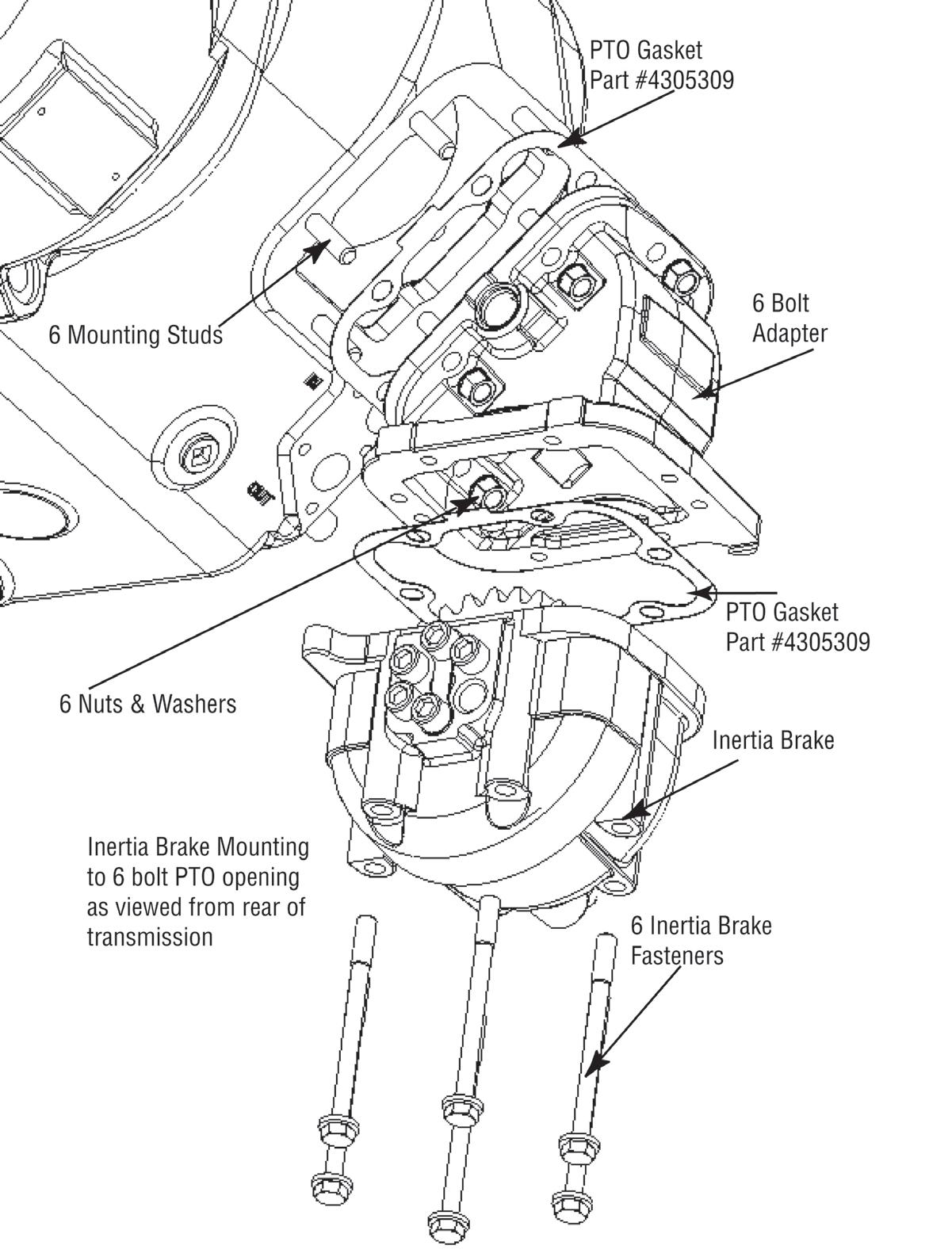
11. Lifting Eyes and Sensor Position - The Eaton shift bar housing, ECU, sensor, and lifting eye retaining fasteners as well as those associated with any gasketed transmission surfaces are not intended for use in securing additional OEM brackets. Removal of these can compromise transmission system operation and overall system reliability.[see page 90] 12. Air Dryer Requirements - It is required to use a high quality commercially available air dryer in the air supply line before the transmission.[see page 25] 13. Fan Drive Requirements - The recommended practice is for the engine fan to be wired into the engine ECM, this includes the manual fan override switch. The OEM should use fan clutches that can be controlled by the engine (i.e. electromechanical). Failure to comply with this recommended practice can cause Eaton transmissions to inhibit shifts when the engine fan is on. 14. PTO and Auto Neutral Options - Eaton recommends the OEM provide a connector and wiring coming from the Transmission ECU 38-Way (Vehicle Interface) with the AW3 Auto Neutral and PTO wires installed.[see page 72] 15. Gear Display - The OEM is responsible for supplying the Gear Display, Wiring, and its location per FMVSS.[see page 13] 16. Tone Module - The OEM is responsible for supplying the tone module with the Eaton Shift Lever or OEM Driver Interface Device. The tone module is supplied in the Eaton Push Button Shift Control.[see page 14] 17. Transmission Component Temperature Requirements - The temperature limit for all electrical and air system components is 250F° (121°C). This temperature limit must not be exceeded. If sufficient air gap clearance can not be achieved, the OEM must provide Eaton approved heat shielding.The systems to be protected are the Shift Motors, Sensors, Solenoids, Air Filter Regulator, Inertia Brake, Wire Harness, Transmission Controller, Oil Cooler and Hoses, and the Transmission Case. 18. Engine Configuration - Prior to shipment of Eaton Automated Transmission Systems installed at OEM plants, the engine ECU must contain the proper configuration settings. For the proper engine configuration settings required for Eaton Automated Transmission operation refer to the “Engine Configuration Settings Installation Guide” on roadranger.com under the literature center. 19. Typical Ignition Interrupt Circuit (MEIIR) - There must be no other systems in the ignition circuit between the MEIIR and the engine ECM. If there are other systems in the ignition circuit between the ignition switch and the MEIIR, contact Eaton for guidance.[see page 66] 20. Battery and Ignition Power - Battery and Ignition power and ground to the TECU must not be switched off during the engine start process.[see page 59][see page 56] 21. Engine Idle Speed - Nominal Engine Idle Speed UltraShift DM3 700 RPM UltraShift AW3 700 RPM