Fuel/Lubrication/Cooling SPECIAL TOOLS A number of special tools must be available to the technician when performing service procedures in this section. Refer to the current Special Tools Catalog for the appropriate tool description. Description
! WARNING Gasoline may be under pressure. Place an absorbent towel under the connector to absorb any gasoline spray when disconnecting.
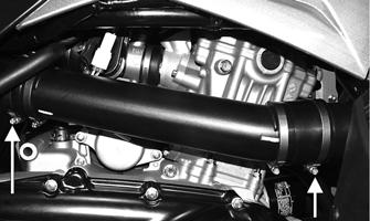
3. Loosen the clamp securing the intake boot to the throttle body; then loosen the clamp securing the intake boot to the intake housing and slide the intake housing rearward.
p/n
Oil Pressure Test Kit
0644-495
Tachometer
0644-275
Fuel Pressure Test Kit
0644-571
NOTE: Special tools are available from the Arctic Cat Service Department.
Electronic Fuel Injection FI691A
! WARNING Whenever any maintenance or inspection is performed on the fuel system during which there may be fuel leakage, there should be no welding, smoking, open flames, etc., in the area.
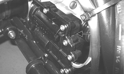
4. Disconnect the MAP/IAT sensor connector, ISC connector, and TPS connector; then loosen the clamp securing the throttle body to the intake manifold boot and slide the throttle body out.
TROUBLESHOOTING 1. Verify that the electric fuel pump is operating by listening for a “whirring” sound for several seconds after the ignition switch is turned to the ON position. If no sound can be heard, see Electric Fuel Pump/ Fuel Level Sensor in this section. 2. Check for a flashing Diagnostic Trouble Code (DTC) and a Malfunction Indicator Light (MIL) in the form of a wrench icon on the LCD. If a code is flashing, see Electrical System- EFI Diagnostic System. 3. Make sure there is sufficient, clean gas in the gas tank.
FI528A
4. Verify that the battery is sufficiently charged to crank the engine over at normal speed.
5. Remove the throttle arm cover and loosen the throttle cable jam nut; then disconnect the throttle cable and remove the throttle body.
5. Check the air filter housing and air filter for contamination. Clean or replace as necessary (see Periodic Maintenance).
Throttle Body
INSTALLING 1. Connect the throttle cable to the throttle arm; then install the throttle cable housing in the throttle body and tighten the jam nut. Install the throttle arm cover and secure with two machine screws. 2. Place the throttle body into the intake manifold boot and tighten the boot clamp securely.
REMOVING 1. Remove the heat shields and seat.
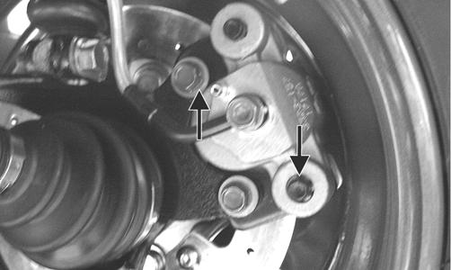
3. Connect the TPS connector, ISC connector, and the MAP/IAT sensor connector.
2. Disconnect the negative battery cable; then remove the gas tank (see Gas Tank in this section).
4. Place the intake housing into the boots and tighten the boot clamps securely. 5. Install the gas tank; then the heat shields and seat.
75