25 minute read
Periodic Maintenance

This section has been organized into sub-sections which show common maintenance procedures for the Arctic Cat ATV. SPECIAL TOOLS A number of special tools must be available to the technician when performing service procedures in this section. Refer to the current Special Tools Catalog for the appropriate tool description.
Compression Tester Kit Oil Filter Wrench Tachometer Timing Light Valve Clearance Adjuster 0444-213 0644-389 0644-275 0644-296 0444-078
NOTE: Special tools are available from the Arctic
Cat Service Department.
Periodic Maintenance Chart
A = Adjust I = Inspect C = Clean L = Lubricate R = Replace T = Tighten
Item Initial Service After Break-In (First Mo or 100 Mi) Every Day Every Month or 100 Miles
Every 3 Months or 300 Miles
Every 6 Months or 500 Miles Every Year or 1500 Miles
As Needed
Battery Fuses Air Filter/Drain Tube Valve/Tappet Clearance Engine Compression Spark Plug
Muffler/Spark Arrester Gas Hoses Throttle Cable Engine-Transmission Oil Level Engine-Transmission Oil/Filter Front Differential/Rear Drive Lubricant Tires/Air Pressure Steering Components V-Belt I I C I R I I C* R I I A I I I R (4000 Mi or 18 Mo) C R I I R (2 Yrs) I I C-L A-R I A R R*/R**/R*** I I R (4 Yrs) I I R I I I R I l R
Suspension (Ball joint boots, drive axle boots front and rear, tie rods, differential and rear drive bellows) Nuts/Cap Screws/Screws Ignition Timing Lights Switches Shift Lever Handlebar Grips Handlebar I I R
I I A I I I R I I R I A-L I R I I R
Gauges/Indicators Frame/Welds Electrical Connections Complete Brake System Brake Pads I I R I l I l C I I C L-R I I* R
Brake Fluid Brake Hoses Coolant/Coolant System
I I R (2 Yrs) I I R (4 Yrs) I I R (2 Yrs) * Service/Inspect more frequently when operating in adverse conditions. ** When using an API certified SM 5W-50 oil. *** When using Arctic Cat ACX All Weather synthetic oil, oil change interval can be increased to every 1,000 miles or every year.
Lubrication Points
It is advisable to lubricate certain components periodically to ensure free movement. Apply light oil to the throttle lever and brake lever pivots.
Air Filter
CLEANING AND INSPECTING FILTER 1.Loosen the clamp securing the front air inlet boot to the air filter housing; then loosen the clamp securing the rear inlet boot to the air box. Remove the inlet pipe.
KC445A

KC446
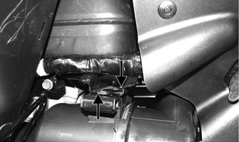
2.Remove two reinstallable rivets from the air filter housing mounting bracket and slide the air filter housing rearward out of the mounting bracket. 3.Turn and release the three locking lugs on the air filter housing and separate the air filter cover from the housing; then remove the air filter element. Separate the foam element from the spring.
KC143
4.Fill a wash pan larger than the element with a nonflammable cleaning solvent; then dip the element in the solvent and wash it. NOTE: Foam Air Filter Cleaner and Foam Air Fil-
ter Oil are available from Arctic Cat.
5.Dry the element. 6.Put the element in a plastic bag; then pour in air filter oil and work the oil into the element. Insert the forming spring into the element with the closely wrapped end of the spring toward the open end of the element.
7.Clean any dirt or debris from inside the air filter housing. 8.Place the filter assembly in the air filter housing making sure it is properly positioned and properly seated with the filter element straight in the housing.
CAUTION
A torn air filter element can cause damage to the ATV engine. Dirt and dust may get inside the engine if the element is torn. Carefully examine the element for tears before and after cleaning it. Replace the element with a new one if it is torn.

KC449
CAUTION
Failure to properly seat and align the filter element may cause severe engine damage.
9.Install the air filter housing cover and secure with the locking tabs.
10.Install the air filter housing assembly into the mounting bracket and secure with two reinstallable rivets. 11.Install the inlet pipe onto the air box; then connect to the air filter assembly making sure the boots are fully engaged. Tighten the clamps securely.
KC445A
CAUTION
Failure to fully engage the inlet boots to the indicator marks could result in ingestion of dirt and severe engine damage.
CHECKING AND CLEANING DRAIN 1.Inspect the drain on the filter housing cover and clean out any dirt or debris.

KC397B
2.Replace any drain that is cracked or shows any signs of hardening or deterioration. 3.Wipe any accumulation of oil or gas from the filter housing and drain.
Valve/Tappet Clearance
To check and adjust valve/tappet clearance, use the following procedure. NOTE: The seat, left-side and right-side engine
covers, and gas tank must be removed for this procedure.
1.Remove the timing inspection plug and spark plug; then remove the tappet covers (for more detailed information, see Engine/Transmission - Servicing
Top-Side Components).

CF005
2.Rotate the crankshaft to the TDC position on the compression stroke. NOTE: At this point, the rocker arms and adjuster
screws must not have pressure on them.
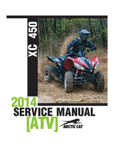
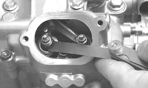
Feeler Gauge Procedure Using a feeler gauge, check each valve/tappet clearance. If clearance is not within specifications, loosen the jam nut and rotate the tappet adjuster screw until the clearance is within specifications. Tighten each jam nut securely after completing the adjustment.
CAUTION
The feeler gauge must be positioned at the same angle as the valve and valve adjuster for an accurate measurement of clearance. Failure to measure the valve clearance accurately could cause valve component damage. VALVE/TAPPET CLEARANCE
Intake Exhaust 0.076-0.127 mm (0.003-0.005 in.) 0.152-0.203 mm (0.006-0.008 in.)
CC007DC
Valve Adjuster Procedure
A.Place the Valve Clearance Adjuster onto the jam nut securing the tappet adjuster screw; then rotate the valve adjuster dial clockwise until the end is seated in the tappet adjuster screw.
B.While holding the valve adjuster dial in place, use the valve adjuster handle and loosen the jam nut; then rotate the tappet adjuster screw clockwise until friction is felt.
C.Align the valve adjuster handle with one of the marks on the valve adjuster dial.
D.While holding the valve adjuster handle in place, rotate the valve adjuster dial counterclockwise until proper valve/tappet clearance is attained. NOTE: Refer to the appropriate specifications in
Feeler Gauge Procedure sub-section for the proper valve/tappet clearance.
NOTE: Rotating the valve adjuster dial counter-
clockwise will open the valve/tappet clearance by 0.05 mm (0.002 in.) per mark.
E.While holding the adjuster dial at the proper clearance setting, tighten the jam nut securely with the valve adjuster handle. 3.Install the timing inspection plug. 4.Place the two tappet covers with O-rings into position; then tighten the covers securely. 5.Install the spark plug; then install the timing inspection plug.
Testing Engine Compression
To test engine compression, use the following procedure. 1.Remove the high tension lead from the spark plug. 2.Using compressed air, blow any debris from around the spark plug. ! WARNING
Always wear safety glasses when using compressed air.
3.Remove the spark plug; then attach the high tension lead to the plug and ground the plug on the cylinder head well away from the spark plug hole. 4.Attach the Compression Tester Kit. NOTE: The engine must be warm and the battery
must be fully charged for this test.

5.While holding the throttle lever in the full-open position, crank the engine over with the electric starter until the gauge shows a peak reading of 95-115 psi (five to 10 compression strokes). 6.If compression is abnormally low, inspect the following items.
A.Verify starter cranks engine over at normal speed (approximately 400 RPM).
B.Gauge functioning properly.
C.Throttle lever in the full-open position.
D.Valve/tappet clearance correct.
E.Valve not bent or burned.
F.Valve seat not burned. NOTE: To service valves, see Engine/Transmission -
Servicing Top-Side Components.
8.If compression is now evident, service the piston rings (see Engine/Transmission - Servicing Top-Side
Components).
Spark Plug
A light brown insulator indicates that a plug is correct. A white or dark insulator indicates that the engine may need to be serviced. To maintain a hot, strong spark, keep the plug free of carbon.

ATV-0051
CAUTION
Before removing a spark plug, be sure to clean the area around the spark plug. Dirt could enter engine when removing or installing the spark plug.
Adjust the gap to 0.7-0.8 mm (0.028-0.032 in.) for proper ignition. Use a feeler gauge to check the gap.
ATV0052C
When installing the spark plug, be sure to tighten it securely. A new spark plug should be tightened 1/2 turn once the washer contacts the cylinder head. A used spark plug should be tightened 1/8 - 1/4 turn once the washer contacts the cylinder head.
Liquid Cooling System
NOTE: Debris in front of the engine or packed between the cooling fins of the radiator can reduce cooling capability. Using a garden hose, wash the radiator to remove any debris preventing air flow.
Do not use a pressure washer to clean the radiator core. The pressure may bend or flatten the fins causing restricted air flow, and electrical components on the radiator could be damaged. Use only a garden hose with spray nozzle at normal tap pressure.
The cooling system capacity can be found in the specifications chart. The cooling system should be inspected daily for leakage and damage. If leakage or damage is detected, take the ATV to an authorized Arctic Cat ATV dealer for service. Also, the coolant level should be checked periodically.
CAUTION
Continued operation of the ATV with high engine temperature may result in engine damage or premature wear.
NOTE: High engine RPM, low vehicle speed, or
heavy load can raise engine temperature. Decreasing engine RPM, reducing load, and selecting an appropriate transmission gear can lower the temperature.
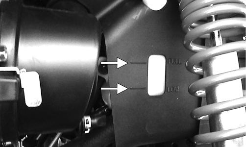
When filling the cooling system, use a coolant/water mixture which will satisfy the coldest anticipated weather conditions of the area in accordance with the coolant manufacturer’s recommendations. While the cooling system is being filled, air pockets may develop; therefore, run the engine for five minutes after the initial fill, shut the engine off, and then fill the cooling system to the bottom of the stand pipe in the radiator neck. Checking/Filling 1.Locate the coolant reservoir on the right side behind the radiator. 2.Remove the cap and fill with the appropriate coolant until coolant level is between the LOW and FULL lines. Do not overfill.
KC396A
3.Install the cap on the reservoir.
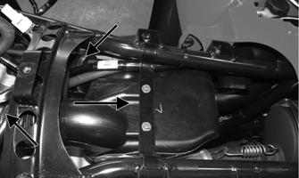
Muffler/Spark Arrester
At the intervals shown in the Periodic Maintenance Chart, clean the spark arrester using the following procedure. 1.Remove the cap screws securing the spark arrester assembly to the muffler; then loosen and remove the arrester.
! WARNING

KC374A
2.Using a suitable brush, clean the carbon deposits from the screen taking care not to damage the screen. NOTE: If the screen or gasket is damaged in any
way, it must be replaced.
3.Install the spark arrester assembly with gasket; then secure with the cap screws. Tighten to 48 in.-lb.
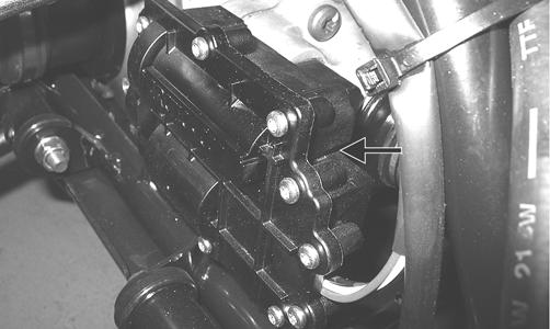
Adjusting Throttle Cable
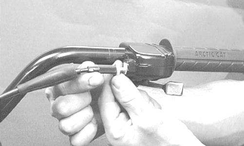
To adjust the throttle cable free-play, follow this procedure. 1.Slide the rubber boot away; then loosen the jam nut from the throttle cable adjuster.
AL611D
2.Turn the adjuster until the throttle cable has proper free-play of 3-6 mm (1/8-1/4 in.) at the lever.
Adjusting Engine RPM (Idle)
NOTE: Engine idle RPM is not adjustable on this
model.
Engine/Transmission Oil - Filter
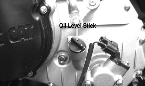
The engine should always be warm when the oil is changed so the oil will drain easily and completely. 1.Park the ATV on level ground. 2.Remove the seat and left-side engine cover. 3.Remove the oil level stick/filler plug.
KC0051A
4.Remove the drain plug from the bottom of the engine and drain the oil into a drain pan.
733-441A
5.Remove the oil filter plug from the filter mounting boss (located on the front side of the transmission case) and allow the filter to drain completely. Install the plug and tighten securely. 6.Using the adjustable Oil Filter Wrench and a suitable wrench, remove the old oil filter. NOTE: Clean up any excess oil after removing
the filter.
7.Apply oil to a new filter seal ring and check to make sure it is positioned correctly; then install the new oil filter. Tighten securely. 8.Install the engine drain plug and tighten to 20 ft-lb.
Pour the specified amount of the recommended oil in the filler hole. Install the oil level stick/filler plug.
CAUTION
Any oil used in place of the recommended oil could cause serious engine damage. Do not use oils which contain graphite or molybdenum additives. These oils can adversely affect clutch operation. Also, not recommended are racing, vegetable, non-detergent, and castor-based oils.
9.Start the engine (while the ATV is outside on level ground) and allow it to idle for a few minutes. 10.Turn the engine off and wait approximately one minute. 11. Remove the oil level stick and wipe it with a clean cloth. 12. Install the oil level into engine case. NOTE: The oil level stick should be threaded into
the case for checking purposes.
13. Remove the oil level stick; the engine oil level should be above the illustrated “L” mark but not higher than the illustrated “F” mark.
CAUTION
Do not over-fill the engine with oil. Always make sure that the oil level is above the “L” mark but not higher than the “F” mark.

ATV-0100AA
14.Inspect the area around the drain plug and oil filter for leaks. 15.Install the left-side engine cover and the seat.
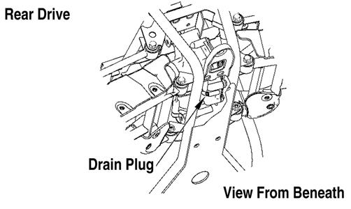
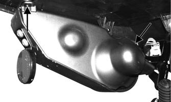
Front Differential/Rear Drive Lubricant
When changing the lubricant, use approved SAE 80W-90 hypoid gear lube. To check lubricant, remove the rear drive filler plug; the lubricant level should be 1 in. below the threads of the plug. If low, add SAE approved 80W-90 hypoid gear lubricant as necessary.
To change the lubricant, use the following procedure. 1.Place the ATV on level ground. 2.Remove each fill plug.

KC0077B
3.Drain the lubricant into a drain pan by removing the drain plug from each.

ATV0082A
737-651B
4.After all the oil has been drained, install the drain plugs and tighten to 45 in.-lb. 5.Pour the appropriate amount of approved SAE 80W90 hypoid gear lubricant into the filler hole. 6.Install the fill plugs and tighten to 16 ft-lb. NOTE: If the differential/rear drive oil is contami-
nated with water, inspect the drain plug, filler plug, and/or bladder.
CAUTION
Water entering the outer end of the axle will not be able to enter the rear drive unless the seals are damaged.
Tires
TIRE SIZES The ATV is equipped with low-pressure tubeless tires of the size and type listed (see General Information - General Specifications). Do not under any circumstances substitute tires of a different type or size. ! WARNING
Always use the size and type of tires specified. Always maintain proper tire inflation pressure.
TIRE INFLATION PRESSURE Front and rear tire inflation pressure should be 40.0 kPa (5.7 psi).
Driveshaft/Coupling
The following drive system components should be inspected periodically to ensure proper operation.
A.Spline lateral movement (slop).
B.Coupling cracked, damaged, or worn.
Nuts/Bolts/Cap Screws
Tighten all nuts, bolts, and cap screws. Make sure rivets holding components together are tight. Replace all loose rivets. Care must be taken that all calibrated nuts, bolts, and cap screws are tightened to specifications.
Ignition Timing
The ignition timing cannot be adjusted; however, verifying ignition timing can aid in troubleshooting other components. To verify ignition timing, use the following procedure. 1.Attach the Timing Light to the spark plug high tension lead; then remove the timing inspection plug from the left-side crankcase cover. 2.Using the Tachometer, start the engine and run at 1500 RPM; ignition timing should be 10° BTDC. 3.Install the timing inspection plug. If ignition timing cannot be verified, the rotor may be damaged, the key may be sheared, the trigger coil bracket may be bent or damaged, or the ECM may be faulty.
Lights
Rotate the ignition switch to the running lights position; the running lights and taillights should illuminate. Test the brakelights by compressing the brake lever. The brakelights should illuminate. Shift the Hi/Lo beam switch to the Lo position; the low beam headlights should illuminate. In the Hi position, the high beam headlights should illuminate. The running/tail lights will remain illuminated until the ignition switch is switched to the run position. HEADLIGHTS NOTE: The bulb portion of a headlight is fragile.
HANDLE WITH CARE. When replacing a headlight bulb, do not touch the glass portion of the bulb. If the glass is touched, it must be cleaned with a dry cloth before installing. Skin oil residue on the bulb will shorten the life of the bulb.
! WARNING
Do not attempt to remove a bulb when it is hot. Severe burns may result.
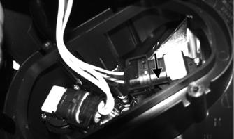
To replace the headlight bulbs, use the following procedure. 1.Remove four screws securing the headlight access panel to the headlight housing.

KC429A
2.Remove the headlight bulb by rotating the bulb assembly and removing from the headlight housing; then spread the retaining clips and disconnect the bulb assembly from the connector.

KC432A
3.Install the new bulb assembly into the connector; then insert the bulb assembly into the housing and rotate to lock. 4.Install the access panel and secure with the screws. TAILLIGHTS-BRAKELIGHTS To replace a taillight-brakelight bulb, use the following procedure. 1.Remove the cap screw and screw securing the taillight housing cover to the taillight housing; then twist and remove the bulb socket.
KC433A

KC434A
2.Turn the bulb socket assembly counterclockwise and remove from the housing. 3.Press in and turn the bulb counterclockwise to remove. Press in and turn clockwise to install the bulb. 4.Insert the bulb socket assembly into the housing and turn it clockwise to secure. 5.Secure the housing cover with the two fasteners.
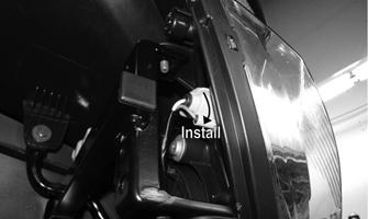
RUNNING LIGHTS The running lights are located outboard of the headlights. To replace the running light bulbs, use the following procedure. 1.Rotate the bulb socket counterclockwise to release from light housing; then press in on the bulb and turn counterclockwise to release from the socket.
KC428A
2.Install a new bulb and press in rotating clockwise to secure; then place the socket into the light housing and turn clockwise to secure.
KC428B
BACK-UP LIGHTS The back-up lights are located outboard of the taillightsbrakelights. To replace the back-up light bulbs, use the following procedure. 1.Remove the taillight housing cover. 2.Remove two screws securing the back-up light socket to the taillight housing. Account for a small gasket.


KC436A
3.Twist the bulb counterclockwise and remove from the socket; then press in and rotate the new bulb clockwise. 4.Secure the socket to the housing making sure the gasket is in place. 5.Install the housing cover. CHECKING/ADJUSTING HEADLIGHT AIM The headlights can be adjusted vertically and horizontally. The geometric center of the HIGH beam light zone is to be used for vertical and horizontal aiming. 1.Position the ATV on a level floor so the headlights are approximately 6.1 m (20 ft) from an aiming surface (wall or similar aiming surface).

ATV-0070C
NOTE: There should be an average operating load on the ATV when adjusting the headlight aim.
2.Measure the distance from the floor to the mid-point of each headlight. 3.Using the measurements obtained in step 2, make horizontal marks on the aiming surface. 4.Make vertical marks which intersect the horizontal marks on the aiming surface directly in front of the headlights. 5.Switch on the lights. Make sure the HIGH beam is on. DO NOT USE LOW BEAM. 6.Observe each headlight beam aim. Proper aim is when the most intense beam is centered on the vertical mark 5 cm (2 in.) below the horizontal mark on the aiming surface.
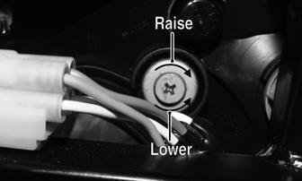
7.Adjust each headlight by turning the adjuster screw clockwise to raise the beam or counterclockwise to lower the beam.
KC406A
Shift Lever
CHECKING ADJUSTMENT

KC165
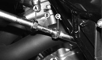
With the engine stopped and the brake lever lock engaged, turn the ignition switch to the ON position; then shift the transmission into each of the gear positions and note that the gear position indicated on the LCD corresponds to the gear position selected by the lever. If the indicator does not correspond to the selected gear, it will be necessary to test drive the ATV to determine if the gear position switch is faulty or the shift lever needs adjustment. If the ATV functions in the gear selected by the shift lever, troubleshoot the gear position switch (see Electrical System). If the ATV functions but the shift lever does not correspond with the gear indicated on the LCD, adjust the shift linkage. To adjust, proceed to ADJUSTING. ADJUSTING 1.Remove the seat; then remove the left-side engine cover. 2.With the ignition switch in the ON position, loosen jam nut (A) (left-hand threads); then loosen jam nut (C) and with the shift lever in the reverse position, adjust the coupler (B) until the transmission is in reverse and the “R” icon appears on the LCD.
KC437A
3.Tighten the jam nuts securely; then shift the transmission to each position and verify correct adjustment. 4.Install the left-side engine cover and seat making sure the seat locks securely in place.
Frame/Welds
The frame and welds should be checked periodically for damage, bends, cracks, deterioration, broken components, and missing components. If replacement or repair constitutes removal, see Steering/Frame.
Hydraulic Brake Systems
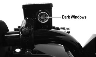
CHECKING/BLEEDING The hydraulic brake systems have been filled and bled at the factory. To check and/or bleed a hydraulic brake system, use the following procedure. 1.With the master cylinders in a level position, check the fluid level in the reservoirs. On the hand brakes if the level in the reservoir is adequate, the sight windows will appear dark. If the level is low, the sight windows will appear clear.
KC387A
2.Compress the brake levers/pedal several times to check for a firm brake. If the brake is not firm, the systems must be bled. To bleed the brake systems, use the following procedure.
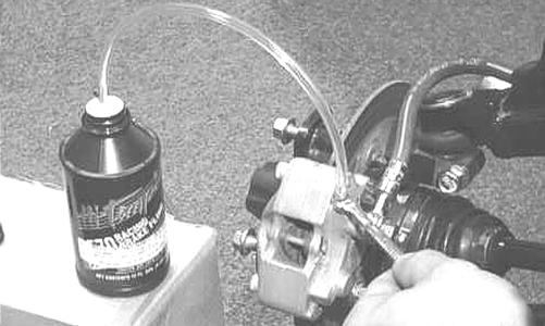
A.Remove the cover and fill the appropriate reservoir with DOT 4 Brake Fluid (left hand brake/foot pedal - rear system; right hand brake - front brake system); then install and secure the cover. B.Slowly compress the brake lever several times. C.Remove the protective cap, install one end of a clear hose onto one FRONT bleeder screw, and direct the other end into a container; then while holding slight pressure on the right brake lever, open the bleeder screw and watch for air bubbles.
Close the bleeder screw before releasing the brake lever. Repeat this procedure until no air bubbles are present.
AF637D

PR377C
NOTE: During the bleeding procedure, watch the
appropriate reservoir very closely to make sure there is always a sufficient amount of brake fluid. If low, refill the reservoir before the bleeding procedure is continued. Failure to maintain a sufficient amount of fluid in the reservoir will result in air in the system.
D.Repeat step C until the brake lever is firm.
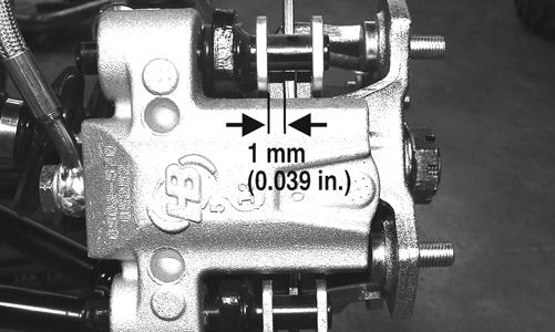
E.At this point, perform steps B, C, and D on the other FRONT bleeder screw; then move to the REAR bleeder screw and follow the same procedure using the left brake lever or foot pedal. 3.Carefully check the entire hydraulic brake system that all hose connections are tight, the bleed screws are tight, the protective caps are installed, and no leakage is present. INSPECTING HOSES Carefully inspect the hydraulic brake hoses for cracks or other damage. If found, the brake hoses must be replaced. CHECKING/REPLACING PADS The clearance between the brake pads and brake discs is adjusted automatically as the brake pads wear. The only maintenance that is required is replacement of the brake pads when they show excessive wear. Check the thickness of each of the brake pads as follows. 1.Remove a front wheel. 2.Measure the thickness of each brake pad. 3.If thickness of either brake pad is less than 1.0 mm (0.039 in.), the brake pads must be replaced.
Brake fluid that has been drained or bled from the brake system must NEVER be re-used or severe brake system corrosion and damage may occur. Always discard used brake fluid in an appropriate manner.
CAUTION
This hydraulic brake system is designed to use DOT 4 brake fluid only. If brake fluid must be added, care must be taken as brake fluid is very corrosive to painted surfaces.
PR376B
NOTE: The brake pads should be replaced as a set.
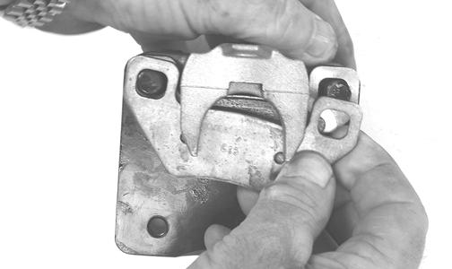
4.To replace the brake pads, use the following procedure.
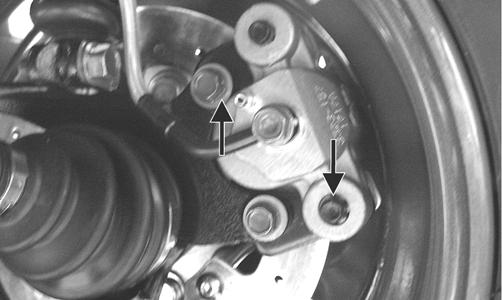
A.Remove the cap screws securing the caliper to the knuckle; then remove the pads.
PR237
C.Secure the caliper to the knuckle and/or axle housing with new cap screws with “patch-lock.”
Tighten to 20 ft-lb.
PR377B
5.Install the wheel. Tighten using a crisscross pattern in 20 ft-lb increments to 80 ft-lb. 6.Burnish the brake pads.

Burnishing Brake Pads
Brake pads must be burnished to achieve full braking effectiveness. Braking distance will be extended until brake pads are properly burnished. To properly burnish the brake pads, use the following procedure.
1.Choose an area large enough to safely accelerate the
ATV to 30 mph and to brake to a stop. 2.Accelerate to 30 mph; then compress brake levers or brake pedal to decelerate to 0-5 mph. 3.Repeat procedure on each brake system twenty times. 4.Verify the brakelights illuminate when the hand lever is compressed or the brake pedal is depressed.
! WARNING
Failure to properly burnish the brake pads could lead to premature brake pad wear or brake loss. Brake loss can result in severe injury.
Checking/Replacing VBelt
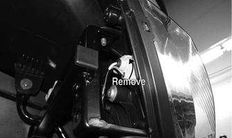
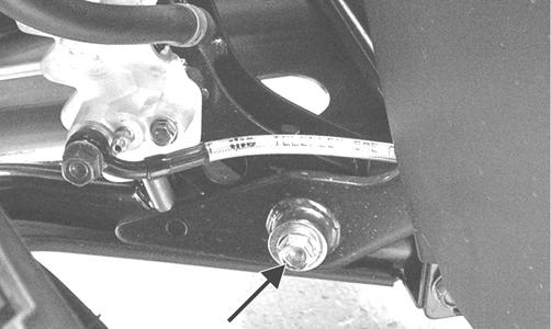
REMOVING 1.Remove the cap screw securing the brake pedal to the frame. Account for a flat washer.
KC149A
2.Remove the cotter pin from the brake clevis pin; then slide the brake pedal away from the frame sufficiently to remove the clevis pin.

KC439
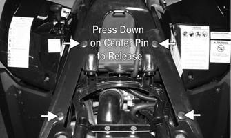
3.Lower the brake pedal down to the foot wells and remove the reinstallable rivet from the CVT cut-out in the foot well. 4.Remove the cap screws from the CVT cover and remove the cover accounting for two alignment pins. 5.Remove the nut securing the movable drive face to the clutch shaft; then remove the movable drive face assembly being careful not to let the rollers fall out.
Account for a bushing.

KC127

KC128
6.Thread a cap screw from the V-belt cover into the driven pulley fixed face and push the movable face open allowing the V-belt to drop down between the pulley faces approximately 3/4 in.
KC137
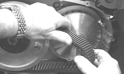
7.Pinching the V-belt together in front of the driven pulley, pull it forward and outward off the clutch shaft; then remove it from the driven pulley.
KC136
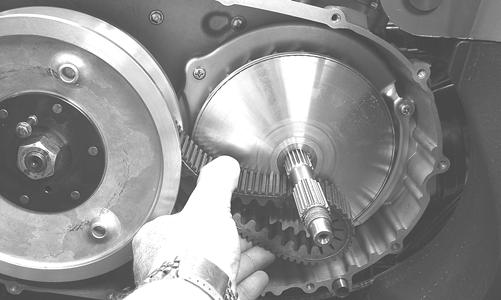
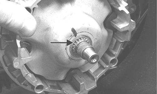
8.Inspect the faces of the drive and driven pulleys for scoring, pitting, cracks, or grooving; then clean any dirt and debris from the V-belt housing and cover. INSTALLING 1.Place the V-belt onto the driven pulley making sure the arrows on the belt point in the direction of rotation; then pinch the belt together in front of the driven pulley and place it over the clutch shaft.
KC135

KC131
2.Install the bushing over the clutch shaft; then install the movable drive face assembly on the clutch shaft.
KC128
KC138
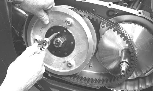
3.With two drops of red Loctite #271 on the threads and with the splines of the clutch shaft protruding through the movable drive face, install the nut and tighten to 147 ft-lb.
KC152A

KC141
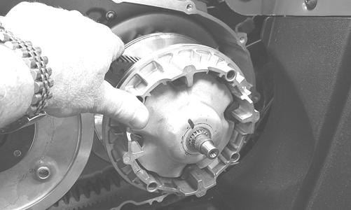
4.Remove the cap screw from the fixed driven face; then rotate the pulleys counterclockwise until the driven pulley faces are together. 5.With the two alignment pins installed in the V-belt housing and a new V-belt cover gasket in place, install the V-belt cover. Using the pattern shown, secure with the cap screws tightened to 8 ft-lb.

KC142A

KC153A
6.Install the clevis pin connecting the brake pedal to the master cylinder and secure with a new cotter pin; then install the cap screw and flat washer securing the brake pedal to the frame and tighten to 20 ft-lb.